
The Climatic Envelope
It is possible to design buildings to control their internal environments both actively and passively. A passively designed building “dances” with the ambient energy flows around it – a strategic arrangement of the form and fabric of the building captures and stores heat when it is needed, and avoids or releases it when it is not. An active environmental control strategy involves supplying or removing energy from the space through mechanical means such as solar-thermal hydronic heating, air conditioning, or a gas furnace. Buildings should be optimized to employ passive strategies and to rely on active strategies as required (using renewable energy whenever possible) to back up those passive systems. Even in cool climates, modern (well-insulated, airtight) offices tend to produce a level of heat from their occupants, lighting, computers, etc. so that they are more likely to need cooling than heating. With domestic environments, it is usually the opposite, with heating and cooling loads being dominated by outside conditions.
Passive Thermal Envelope
The form and orientation of a building dictate both solar gain, “the greenhouse effect,” and natural air movement – air exchange. The fabric of the building dictates its ability to absorb energy, through thermal mass, and to present a barrier to energy flows, through insulation. Often, the architect has to deal with conflicting variables – in a hot climate a large expanse of glass offering a panoramic view, but facing the sun, will require shading during the hottest part of the day.
Sound and Light
Both sound and light are described as wavelengths which are measured as frequencies. The design of a building and the building fabric influence the ways in which both sound and light waves will behave. Acoustically, buildings have to maintain clarity of communication for their occupants and must protect them from noise pollution. Similarly, the maximum use of available daylight can contribute to both the well-being of a building’s occupants and to energy conservation.
Mechanical Heating, Ventilation, and Air-Conditioning
While a certain amount of control over the energy used to heat, cool, and illuminate buildings can be achieved passively through the building fabric (design and orientation), it may also be necessary to employ additional energy sources and energy distribution systems. This section covers mechanical heating, mechanical ventilation and air-conditioning, although these may be designed in tandem with the passive envelope, as with hybrid active/passive cooling systems.
Climatic Envelope / Thermal Mass
Thermal mass is the ability of a material to absorb heat energy. A good deal of heat energy is required to change the temperature of most high-density materials like concrete, brick, and stone. They are therefore said to have high thermal mass. Lightweight materials such as timber generally have low thermal mass. The specific heat capacitance is the property of a material that refers to the amount of heat required to change the temperature of a given mass of that material a certain amount. Water has a very high specific heat (1Btu/lb ºF) and relatively high density, giving it a tremendous ability to store heat with a minimal temperature change. Drums of water have even been used for thermal mass walls in some cases.
Effective use of thermal mass in buildings will tend to moderate temperature extremes, with the resulting indoor temperature oscillating around the average outdoor temperature in the absence of a heat source (such as passive solar gain) or a heat sink. In addition to the reduction of temperature fluctuation, there will also tend to be a lag between outdoor conditions and the indoor temperature response. For example, in an environment subject to hot days and cold nights, thermal mass may be used to absorb heat during the day from direct sunlight (we experience this when walking into a cathedral, mosque, or castle in a hot climate) and it will re-radiate this warmth back into the buidling during the night. Thermal mass acts as a “thermal battery” by storing excess heat and releasing it during cooler periods.
Strategic use of thermal mass is an essential and time-tested passive strategy. Most modern high-mass materials also have a high thermal conductivity (e.g. concrete) and therefore need to be placed inside of insulation so that their stored heat is not released to the outside before it becomes useful in the building, and to minimize excessive heat flow through the building envelope.
Trombe Wall
The trombe wall is a specialized application of thermal mass. Heat from the sun is trapped between window glazing and a dense, masonry wall (see Windows and Glazing, page 90). The wall stores heat for release into the building later in the day. Edward Morse patented the design in 1881. However, it really became efficient only with the advent of insulated glass (to prevent heat loss back to the outside) and with the introduction of either natural or fan-assisted ventilation to encourage heated air to flow into the interior through convection. The space between the window and the wall then becomes a solar thermal collector.

1 Direct solar gain.
2 Indirect solar gain: trombe wall.
3 Labyrinth, Federation Square.
4 Federation Square, Melbourne, Australia, Lab Architecture Studio with Atelier 10. This “thermal labyrinth” acts as a battery pack that can be flushed with colder night air during summer so that it can cool incoming air during the day. The basic idea is simply that air is exposed to a large surface area of concrete on its way into the building by passing at low velocity down a tunnel.
Climatic Envelope / Thermal Insulation: Principles
Insulation acts as a barrier to heat flow and is essential to keep buildings warm or cool. Depending on the climate, it is necessary to establish whether the insulation is predominantly needed to keep heat in or out (or both).
Conduction, Convection, and Radiation
Heat will flow (or transfer its energy) by one of the following mechanisms. Conduction is the transfer of energy through matter from particle to particle, from atom to atom. For example, a spoon placed in a cup of hot liquid becomes warmer because the heat from the liquid is conducted along the spoon. Convection is the transfer of heat energy in a gas or liquid by movement of currents: heat leaves the hot cup as the currents of steam and air rise. Radiation is the direct transfer of energy, without the aid of fluids or solids, through electromagnetic waves; sunlight radiates heat to our planet.
Thermal Conductivity
Materials with a high thermal mass are not necessarily good insulators. Good insulative properties depend upon the ability of a material to resist heat passing through it. Such materials are said to have poor thermal conductivity. For example, rubber is a poor conductor of heat, brick is good, concrete is better. The surface of a material will affect its thermal conductivity through its ability to reflect heat energy. Dark, matt or textured surfaces absorb and reradiate more energy than light, smooth, reflective surfaces.
U Value
The ability of a material (such as in a window, wall, or roof) to transfer heat energy from one side to the other is measured as the thermal transmission rate per area per temperature difference. It is referred to as conductance or U value. The formula is expressed as Btu per hour per square foot of surface per degree Fahrenheit (Btu/hr/ft² °F), and the resulting figure is known as the U value or conductance.
R Value
The insulative qualities of walls, floors, and roofs are generally reported in terms of resistance or R value. This is simply the arithmetic inverse of U value and is expressed as (hr ft² °F/Btu). Resistance values are useful because the R value of the individual layers of an assembly may be totaled to obtain the value for the entire section.
Note: A penguin is able to maintain an internal body temperature of around 95ºF when the outside temperature is -58ºF. A ¼ in layer of down (tiny feathers measured in microns) produces millions of tiny air pockets to insulate the penguin.

1 Where thermal mass is employed to store heat energy, an external layer of insulation prevents heat reradiating to the outside. Similarly, insulated glazing can prevent heat loss from a Trombe wall at night.
2 Thermal imaging techniques (thermography) use infrared cameras to identify heat flow through buildings.
Climatic Envelope / Thermal Insulation: Types
Products used to enhance the insulative capacity of buildings currently use two basic methods, bulk insulation or reflective insulation.
Bulk Insulation
This resists the transfer of conducted or convected heat by relying on pockets of trapped air within its structure. Its thermal resistance is essentially the same regardless of the direction of heat flow through it. Bulk insulation includes natural materials such as cotton, wool, and cellulose, as well as synthetic materials such as fiberglass batts, polystyrene, and polyurethane foams.
Foam insulations have the added benefit that they seal the building envelope, limiting air leakage.
Radiant Barriers
Radiant barriers usually have an aluminum foil surface and must be separated from adjacent materials by an airspace so that heat cannot be conducted directly through the material. The radiant barrier then becomes a very effective defense against heat transfer because it has a very poor ability to absorb or re-radiate long-wave radiation. This property is called low emissivity. Because the surface is not in contact with other materials, it cannot conduct heat to them directly, so the only heat transfer pathway left is convection.
Thermal Bridging
This is a term used for situations where a thermally conductive material traverses from the inside to the outside of the building, allowing heat or cold to pass through it.

1 Bulk insulation in a cavity wall. This type of insulation may also consist of a thinner, multilayered fabric combining bulk and reflective insulators. Other useful insulators include paper pulp, sheep’s wool and penguins (well, not penguins actually).
2 Aerogel: created by Steven Kistler in 1931, Aerogel is a low-density material in the form of a gas-filled gel. Aerogels made from silica and carbon are able to nearly eliminate heat transfer by convection and conduction.
3 Sections through walls of differing composition, both producing a 53° F difference between the inside and outside.
Climatic Envelope / Air Movement: Natural Ventilation
Ventilation is the exchange of stale air with fresh air within a building. This can have a number of effects. It can supply clean air, i.e. dilute carbon dioxide and supply oxygen; it can replace hot air with cool air; and it can lower relative humidity and prevent condensation (where water vapor in the air collects on surfaces). Ventilation may also be needed to remove smoke in the event of a fire.
Rate of Change
Ventilation is normally measured in terms of the number of times that the air in a room is completely replaced in an hour (air changes per hour: ac/h). For a typical office the recommended rate is between 4 and 6 ac/h; for a restaurant, it is between 10 and 15 ac/h.
Natural Ventilation
Naturally ventilated buildings are designed to promote air exchange without the use of mechanical means. Natural ventilation relies on pressure differences to move air from areas of higher pressure to areas of lower pressure. When windows are open on two sides of a space, and a breeze is coming from one direction, positive pressure is produced on the windward side and negative pressure on the leeward side of the building. This pressure differential tends to suck air through the space. Cross ventilation is the most basic of natural ventilation strategies.
Stack Effect
The stack effect is a form of convection. Because warm air is less dense than cold air, a building with openings at both the top and the bottom will experience a pressure difference. In the hot season, the warmer indoor air will rise (through thermal buoyancy) and reduce the pressure at the base, encouraging denser, cooler air to infiltrate. The greater the thermal difference and the height of the structure, the greater this effect. In a tall building with a sealed envelope the stack effect can create significant pressure differences: stairwells and lift shafts, etc. need to be controlled to prevent the spread of smoke in the event of a fire.
A chimney will encourage the stack effect by acting like a venturi nozzle – where gas from a large chamber accelerates when passing through a small chamber into a second large chamber due to the pressure differences (similar to the uplift developed by an airfoil shape which creates a pressure differential above and below a wing). A chimney will draw air vertically through a wind or breeze passing over its top and creating a pressure difference.

1 Cross-ventilation. Warm air rises or, more accurately, heat flows from areas of higher temperature to areas of lower temperature.
2 Natural air flow assists convection of warm air from a Trombe wall into the interior.
3 Wind is described in terms of the direction from which it originates, as read on a compass. For any location, wind will, on average, tend to come from a particular direction; this is known as the prevailing wind.
4 A wind map, known as a wind rose, is used to describe the average wind direction for any location, as in this random example. Each circle represents the percentage of time the wind blows from a particular direction. Such information can be used when orientating structures to make use of natural air movement or to assess wind impact on a façade.
Climatic Envelope / Air Movement: Passive Control
See also: Tepee p136
30 St. Mary Axe p176
Davies Alpine House p180
In temperate climates, adequate ventilation can usually be achieved by small openings – trickle ventilators – that are positioned to maximize air movement and wind pressures from the local environment. These can be controlled – opened and closed – using manual “dampers.” The building envelope should be as airtight as possible, with fresh air introduced intentionally as needed. For rapid ventilation of rooms, windows can be made to open!
Wind Scoops and Wind Cowls
While a wind scoop employs the principle of catching the wind and forcing it downward into the building (and is therefore constructed to offer an opening towards the prevailing wind), a cowl such as those used on traditional oast houses works in the opposite way to encourage air to be sucked out of the building.
Solar Chimney
A centuries-old idea, the solar chimney is a way of amplifying the stack effect by heating the chimney to produce greater temperature and pressure differences. Chimneys are constructed with a large area of thermal mass (which may be painted black) facing the sun. An updraft is created by the added buoyancy of the air in the chimney, creating suction at openings at the building’s base which ventilate the space.
Evaporative Cooling
If you wet the back of your hand and then blow on it, your skin surface feels cooler. That’s evaporative cooling. When air comes into contact with water, some of the water is evaporated into the air unless it is already at saturation. In the phase change process from liquid water to vapor, the air transfers some of its sensible heat (heat that affects air temperature) to latent heat (energy used to achieve the phase change).) The result is that the air temperature drops and the relative humidity rises; a very effective comfort strategy in hot-dry climates, but not in hothumid ones. The amount of temperature drop is largely a function of the amount of moisture already present in the air. Evaporative cooling is a time-honored tradition in many desert cultures; for example the Islamic courtyard pool provides both a source of evaporative cooling and a psychological cooling effect.
Passive Down-draft Cooltower
Another hot-dry climate cooling technique is the passive down-draft cooltower. Water is pumped over pads located at the top of a hollow tower. This water evaporates, cooling the air. The cool, dense air “falls” through the tower and exits through large openings at its base. Modern mechanical evaporative coolers work in much the same way.

1 Passive down-draft cooler.
2 The principle employed by a wind cowl is that air passing around the curved surface creates a negative pressure around the opening, thus sucking out the air from within.
3 Traditional Middle Eastern “wind catchers.” A wind catcher is a tower that is capped but has openings along the sides. By closing all but the one side that faces away from the incoming wind, air is drawn upwards; due to the height of the tower, the pressure gradient that results from a passing breeze helps to suck the warmer air out from below. Opening the side facing the wind would push air down the shaft.
4 Traditional Middle Eastern wind scoops.
5 Oast houses were used in southern English counties for drying hops. Cowls on the roofs provided an exhaust for the hot air used in the drying process and were able to rotate by using a wind vane.
6 Modern wind cowls at Beddington, UK, are designed to maximize the effect of a passing breeze, both through aerodynamics and by swivelling as the wind changes direction.
7 Passive down-draft cooltowers.
Climatic Envelope / Windows and Glazing
See also: Tropical House p152
The USA Pavilion p162
HSBC Headquarters p168
Windows typically represent the most important pathways for heat gains and losses in modern buildings. In hot periods the transmission of solar radiation into a building through its windows can cause overheating, while in cooler climates heat loss from inside the building through windows can greatly reduce the building’s warmth. These factors can be mediated through solar shading and through the type of glazing used.
Balancing Gains and Losses
As with all heat transfer, heat will flow from the warm side to the cool side of a window. Windows are usually poor insulators compared to solid walls and roofs, and they are nearly transparent to solar radiation, so they represent a large component of the heat gains and losses of a building. Windows facing the sun often gain more solar energy during the day than they lose at night. There are several processes that influence rates of heat loss through glass and window components. Heat loss through windows takes place through both the glazing and frame edges mainly by conduction.
Double Glazing
The insulative quality of a window can be greatly improved by sandwiching two or more panes of glass together using spacers along the edges to produce a sealed air gap. The best spacing to minimize convection losses in double glazing is estimated at 1⁄2-5⁄8 in; stationary air is not a good conductor. Window frames must also be designed in such a way to maximize insulation. Thermally speaking, preferred frame materials are those with low conductivity (such as wood or fiberglass), or frames that are thermally broken, such as aluminum with a lowconductivity plastic strip that connects the inner and outer portions of the frame section.
The Greenhouse Effect
Solar radiation reaching the surface of the earth has a short wavelength (because the surface of the sun is hot – 6000 K). However, window glass is better at blocking the long-wave radiation that is re-emitted from internal surfaces (300 K). Short-wave visible light is converted to heat when it is absorbed by materials inside a space, then re-emitted as infrared radiation that cannot pass directly back through glass. Therefore, temperatures increase quickly as heat builds up. This phenomenon is known as the greenhouse effect.
Emissivity
Because ordinary glass readily radiates heat, i.e. has high emissivity, its ability to retain heat can be improved by lowering its emissivity – hence the term low-emissivity or low-E glass. This is achieved with a coating of microscopic pieces of metal on one face of the glass. Some coatings help to reject incoming solar radiation (reduce solar gain).
Other Coatings
Spectrally selective coatings serve to reduce heat gain by blocking radiation of those portions of the electromagnetic spectrum that are not visible to the human eye. Tinted coating limit certain wavelengths of visible light )as well as invisible radiation in some cases) and reduce overall light transmission. Mirrored coatings also cut down on visible light transmission into the building. Coatings that cut visible light transmission significantly, however, may result in additional lighting requirements which reduces their energy-saving benefits as well as denying occupants the full benefits of daylight access.

1 The greenhouse effect.
2 Roof overhang designed according to seasonal changes in solar geometry.
3 Brise-soleils, also known as louvred blinds, are designed to prevent solar ingress while maintaining daylight and views.
4 If louvres are placed between glass panels with vents at the top and base they will absorb solar radiation and the heat will be removed by natural convection.
5 Deciduous trees allow the sun to warm a building in winter while shading it in summer.
6 Adjustable brise-soleils – horizontal for predominantly high sunlight.
7 Adjustable brises-soleils – vertical for predominantly low sunlight.
8 Types of double-glazing.
Climatic Envelope / Weathering: Masonry
Whether used for loadbearing, or as infill/cladding for a framed structure, a wall built from stone or concrete blocks or from clay bricks will resist water penetration and wind load if properly constructed. In walls constructed with mortar beds, rain is most likely to penetrate through the joints or where the masonry joins to another material such as at a window opening. Brick, stone or concrete blocks are often pointed along the joints – a thin (roughly ⅜ in) layer of a high-density mortar is applied in order to prevent water penetration. Where movement is likely, due to differential thermal expansion and contraction of materials (such as at door and window openings), a flexible – plastic – material is required, which must also be able to adhere to more than one type of material: examples are lime, putty, and synthetic mastic.
Face Brick
Face brick is the most common type of brick and today is made to standards that require the brick to comply with low water absorption standards. Although a well-built brick wall is water resistant, some moisture inevitably makes its way through the exterior of the envelope. Masonry systems either act as a reservoir to store and gradually release infiltrating moisture (solid masonry construction), or employ a cavity wall system to drain and release any water that makes it past the surface veneer. Two major types of defect can occur in brick construction due to water. Spalling occurs in soft sub-standard brick when absorbed water freezes and crumbles or splits off layers of the brick face. Efflorescence is a deposition of dissolved salts on the surface of the brick that usually results from rainwater leakage into the system where the moisture evaporates back out through the face veneer.
Concrete
Concrete is water resistant, although this varies according to the precise mix and construction techniques. In cast reinforced-concrete walls or columns, steel reinforcing bars may be subject to corrosion if placed too close to the surface of the concrete.
Tiles
Clay, stone, and concrete, as well as other artificial materials, are used to weatherproof roofs and walls in the form of small modular panels – tiles. Strictly a form of cladding (see Cladding Systems, page 94), this traditional method of waterproofing has the advantage that the small modules are easily handled and replaced if they are worn or damaged. Tiles are hung from a subframe in a lapped and/or interlocking manner.

1 Pointing: the mortar joints between brick courses may be detailed in various ways on the outer face. Often a thin layer of harder mortar will be applied to the surface. A Flush, B Recessed (raked), C Bucket Handle, D Weatherstruck.
2 Weatherstruck pointing: a ratio of around 2 parts fine sharp sand to 1 part cement.
3 Cast-concrete wall. The finished surface remains as it was when the timber shuttering was removed, showing the imprint of the wood grain.
4 Clay roof tiles have been profiled to interlock with one another and improve rainwater run-off. These are known as pantiles.
5 Slate tiles have been nailed to a subframe of horizontal timber batons to form a vertical cladding.
Climatic Envelope / Weathering: Cladding Systems
With framed construction and where masonry is not used as infill, it is usual that a subframe is constructed in order to carry the weatherproof “skin” of the building. This sub-frame, along with the skin itself, must also be designed to resist wind load. Subframes may be constructed as infill panels, as curtain walls, or as independent structures (“outriggers”) that carry the entire load of the outer skin.
Cladding Panels
There are many materials that can be manufactured in sheet form and that are either naturally waterproof or may be treated or coated to provide water resistance. Metals such as lead, zinc, steel, and copper may be used, as well as glass-reinforced epoxy (GRE), polycarbonate and, of course, glass. Cladding panels may be composed of layers of different materials (sandwiched or laminated) and opaque panels will usually include some type of lightweight (e.g. foam) core for insulation and stiffening. Panels are normally housed in lightweight subframes (typically aluminum) that are then attached to the superstructure. Flexible connections and sealants are needed for differential thermal expansion.
Ventilation
For the purposes of ventilation, louvres and operable windows or vents are often incorporated into cladding systems.
Curtain Walls
Curtain walls are a type of cladding that is hung off the edge of the floor plate. They transfer their loads to the main structure through independent connections to floors and/or columns.
Planar Systems
By employing special fixings (sometimes known as spiders), glass panels can be attached to a subframe in such a way that they form a continuous surface. The panels are sealed at their edges using a flexible mastic.
Rain Screens
Rain screens are an advanced method of rainwater management that are beneficial in any location, but are particularly desirable in areas with heavy rainfall and wind. The rain screen employs a cladding surface in front of a well-ventilated cavity that separates the water resistant drainage plane from the surface veneer. The rain screen deters rainwater from entering the cavity and equalizes pressure on both sides of the cladding to reduce the chance of moisture penetration beyond the drainage plane. Moisture that does enter the cavity is easily drained out or evaporated via ample ventilation. The vented cavity may provide thermal benefits to the building through self-shading and heat removal from the vented cavity in some cases. Many different cladding systems may be employed in a rain screen system.

1 Lightweight (cold-rolled steel) metal stud framework used to infill main concrete structure.
2 Lightweight, hollow clay bricks used as infill panels.
3 Sheet materials can be formed into stiff panels (e.g. through corrugation or profiling) and can then be fixed directly to the main structure of the building.
4 Wood cladding. Wood sections may be used for weathering and are either horizontally lapped – “shiplapped”, as in a boat hull – or interlocked through “tongues and grooves” cut along the planks. Planks are attached to a subframe, which is in turn fixed to the main structure. Timber starts to decay if its moisture content is much beyond 20 per cent so any exposed timber is normally coated with waterproof paints or varnishes.
5 The surface of copper sheet cladding oxidizes and turns green over time if exposed to moisture, a process known as patination. This does not effect its resistance to water penetration.
6, 7 Cladding panels are prefabricated with built-in brackets for fixing to the main framework.
8 A planar glass screen is fixed to a lightweight steel subframe employing vertical trusses.
9 Glass curtain wall.
Climatic Envelope / Weathering: Membranes
Membranes are waterproof fabrics that can be applied in a variety of ways. In tensile structures, the membrane acts to keep out the wind and rain. While tents were originally made from animal skins, ripstop nylon is the modern material from which tents are made. A lightweight, waterrepellent fabric, it is reinforced with threads interwoven in a cross-hatch pattern so the material resists ripping or tearing.
PVC
Polyvinyl chloride is a thermoplastic, a byproduct of the petrochemical industry, and is produced in the form of a white powder that is blended with other ingredients to form a range of synthetic products. Membrane fabrics are made from PVCcoated polyester. These fabrics are strong in tension and resistant to shear. They are light, flameproof and have a maximum thickness of about 1⁄16 in. There is significant cause for concern related to the environmental impacts of PVC. The manufacture of this plastic releases highly toxic dioxin into the atmosphere and dioxin is once again released at the end of its life cycle if the plastic is burned. Additives with adverse human health impacts in the form of phthalates and heavy metals among others are used to plasticize and stabilize PVC for many applications.
ETFE
Ethylene tetrafluoro ethylene is a fluorocarbon-based polymer. It was designed to be a material with high corrosion resistance and strength over a wide temperature range. Thin and lightweight, it is also extremely translucent.
PTFE
Polytetrafluoroethylene is a fluoropolymer that has the lowest coefficient of friction of any known solid material.
Breather Membranes
A breather membrane is a woven material with spacings large enough to allow water vapor molecules to pass through from inside to outside yet small enough to restrict water liquid molecules coming the other way (microporous). It is therefore both waterproof and vapor permeable and is commonly used as a secondary barrier (underlay) below tiles and slates to aid ventilation within pitched roofs. Breather membranes are also known as vapor permeable underlays (VPUs), and are made from heat-laminated spunbond polypropylene with a polyethylene film.
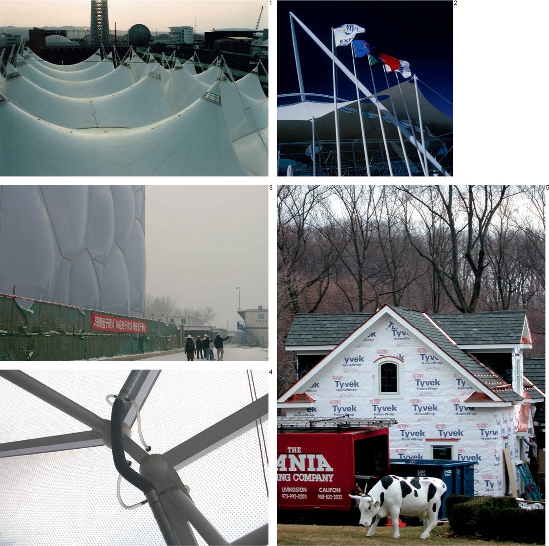
1, 2 Tensile, waterproof membrane made from PVC.
3 The Aquatic Centre, Beijing, China. The structure is clad with hexagonal, inflated “pillows” – double-skinned, pneumatic panels – made from ETFE.
4 Detail of ETFE “pillow” air supply.
5 Tyvek is a brand of spunbonded high-density polythene made by DuPont. It is used as a contemporary replacement for traditional asphaltbased building papers. Such “breather” membranes prevent rain ingress, while allowing moisture to pass out of the building interior.
Climatic Envelope / Weathering: Bonded Surfaces
Felt
Roofing felt is composed of a polyester or glassfiber base saturated and coated with oxidized bitumen and surfaced with either bonded or loose sand or gravel.* Fixed onto a decking with cold applied adhesives or hot bonding bitumen, it is predominantly used as a built-up two- or three-layer system. A final surfacing is generally applied in order to resist general wear and for UV protection; this can be asphalt,** a granule-surfaced cap sheet or loose gravel. Some roofing products incorporate titanium dioxide in the top layer, specifically for UV resistance.
Ethylene Propylene Rubber
This is the basis for a number of products that consist of a single-ply roofing sheet that employs either welded or taped seams along the joints.
Stucco
When the quality of the substrate, be it brick, stone or concrete, is inadequate either from a weathering or aesthetic point of view, a layer of sand and cement mix known as stucco or render may be applied to the face of the building. The wet mix is usually built up in a series of layers for maximum weatherproofing. It may be applied directly to masonry or concrete walls. However, it is also used to weatherproof timber-framed structures where a damp-proof membrane (DPM) is fixed to the timber panelling, followed by metal mesh or timber laths to provide a key for the mortar. Stucco is often painted and may be combined with other natural or artificial additives such as small pebbles (pebbledash) or tiles and mosaics.
*Known as a damp-proof course (DPC), similar products are incorporated into solid walls at low level to prevent “rising damp”, where moisture is sucked up into the wall from the ground below.
**The word asphalt in British English refers to a mixture of mineral aggregate and bitumen (also known as tarmac).
Roofs
As a general rule, roofs will dispose of rainwater in one of two ways. They will either overhang the façade and eject rainwater away from the building (as in 5), or they will contain the water in the manner of a swimming pool (as in 2 and 3).The former are likely to be sloping or pitched to encourage run-off (usually in a controlled manner through gutters and downpipes), while the latter require a completely waterproof membrane and a surrounding dwarf wall or parapet with an integrated drainage system.

1 Over 1m concrete tiles are glued onto the shells that form the roof of the Sydney Opera House, Sydney, Australia.
2 Single-ply roofing sheets with “standing” seams.
3 Felt roof bonded to a timber platform with bitumen.
4 Rendered façade.
5 Pebbledash render.
Climatic Envelope / Weathering: Insulation
Cross-section detail of a glazed curtain wall
Curtain walls are a system of cladding a building in which the cladding elements are normally hung from the edge of the floor plates; the curtain wall façade does not carry any load from the building other than its own dead weight and transfers horizontal (wind) loads through connections at floor level. Here, an extruded aluminum frame is infilled with glass, although all types of cladding panel can be employed as curtain walling.
Cross section detail of ETFE air pillow
ETFE (ethylene tetraflouroethylene) is a man-made flouropolymer whose principle ingredient is fluorite, a common mineral. Extruded ETFE film was first developed in the 1970s, its use as an architectural cladding element being pioneered by Vector Foiltec. The film is deployed as pillows or cushions inflated by air. Fabricators have designed a variety of aluminum sections to grip the foil and create a framing system for connection to a super-structure. Shown here are also the flexible tube connections for maintaining air pressure within the pillows.
Cross section detail of a pitched roof
Pitched roof consisting of structural sawn timber sections and weathered using clay tiles. The apex is clad with a bespoke ridge tile and rainwater is collected in a half-round profiled gutter affixed to a timber facia board.
Cross section detail of sloping roof
Sloping roof shows insulation panels and a glazed opening. The junction of the upper end with the structural wall shows a detail for preventing water ingress while the lower end shows rainwater falling into a squareprofiled gutter.
Cross section detail of brick-faced cavity wall
Vertical section cut through an external wall and printed at a scale of 1:20. At this scale it is possible to describe the shape (by line) and materiality (by fill) of the components that go to make up the wall. This is a brick and block cavity wall with an outer course of bricks, an air gap with a layer of insulation inside the cavity, and concrete blocks forming the inner leaf. A further layer of insulation and a facia panel (together known as dry-lining) are applied internally. The openable (casement) window is constructed from a timber frame with double-glazing, and the floor is made up of a layer of compacted hardcore, a waterproof membrane, a concrete pad, insulation, and a floor surface set on timber batons. There is also a concrete window sill – the little notches in the sills are known as drips and prevent water from seeping back into the brickwork by capillary action. The rebates in the timber frame are for molded seals (i.e. rubber gaskets). There is a reinforced concrete strip foundation.

1 Cross section detail of a glazed curtain wall
2 Cross section details of ETFE air pillow
3 Cross section detail of a pitched roof
4 Cross section detail of a sloping roof clad in lead
5 Cross section detail of brick-faced cavity wall
Sound and Light / Acoustics: Properties of Sound
When the renowned Czech tennis player Ivan Lendl was asked the perennial question “what makes Wimbledon so great?”, he answered without hesitation: “It is the sound of the balls.” Acoustics is the science of sound. Sound or sound waves are a physical disturbance of molecules within a medium, gaseous, liquid or solid, that can be heard by the listener. This molecular disturbance comprises high and low pressure zones described as a wave cycle.
Frequency
The frequency of a sound is determined by the number of wave cycles per second (cps), which is more commonly expressed as Hz after the nineteenth-century German scientist Heinrich Hertz. Good human hearing can hear frequencies from as low as 20 Hz up to 20,000 Hz (20 kHz). Human speech has a more limited frequency range from 200 Hz to 5,000 Hz (5 kHz), whereas a concert orchestra can produce frequencies from 25 Hz to 13,000 Hz (13 kHz). Frequencies below 20 Hz (infrasonic) are sensed as vibration. Often we experience both sound and vibration within buildings. Sound travels at 330 m/sec in air, four and a half times faster in water and faster still through solid substrates. Sound does not travel in a vacuum.
Loudness
Sound pressure determines loudness, and the human ability to detect a huge range of pressure variation led to the use of the decibel (dB – a logarithmic scale) as the standardized measure of sound pressure level (SPL). The dB relates to the human perception of loudness with the threshold of our hearing represented by 0 dB and 140 dB representing the threshold of pain and potential hearing damage. From the quietest to the loudest sound we can endure is a factor of 1 to 10m; an added 20 dB marks a tenfold increase in SPL. Sounds are a combination of frequencies and loudness affected by time.
Reverberation
“You are listening to the room.” Reverberation can be described as the buildup of multiple sounds arriving indirectly to the listener via surface reflections. The reverberation time (r/t) of a room is measured as the time taken for the soundpressure level to fall by 60 dB. Reverberation time is related to the volume and geometry of a room and the absorption coefficients of the surfaces of that space. The reverberation time of any given space will affect the reproduction and intelligibility of a specific sound source. An optimum r/t for speech and electronically amplified music is 1 second, whereas an orchestra may require 1½– 2½ or more. The r/t of St Paul’s Cathedral in London is 12 seconds. With a short r/t you can precisely pinpoint the sound source, which is useful during a lecture or speech, whereas an orchestral performance fills the room with sound (and reflected sound); it is the interaction between physical structure, space and music that you are listening to. In an electro-acoustic environment, where sound is picked up via microphones and then transmitted through a network of speakers, it is possible to shorten or lengthen the r/t, thus altering the notional “acoustic size” of the room and creating a “multi-purpose” space.
Typical Noise Levels |
Loudness dB |
Threshold of hearing |
0 |
Whispering |
20 |
Quiet street |
40 |
Quiet conversation |
50 |
Loud voice / busy office |
60 |
Average traffic |
70 |
Slamming door |
80 |
Motorcycle |
90 |
Nightclub |
100 |
Pneumatic drill |
110 |
Jet aircraft take-off (at 64 ft) |
130 |
Threshold of pain |
140 |
London Noise Map
Part of the Department for Environment Food and Rural Affairs (DEFRA) ambient noise strategy.

Reverberation in a Building
The table below shows typical reverberation times measured at 125 Hz, 500 hz and 2000 hz; these times are averaged out.
Typical Reverberation Time |
r/t secs |
Outdoors |
0.0 |
Bedroom / Living room |
0.4 |
Cinema (recommended) |
1.0 |
Glyndebourne Opera House (new), UK |
1.3 |
Royal Festival Hall, London, UK |
1.4 |
Concert Hall (recommended) |
1.5 |
Carnegie Hall, New York, USA |
1.8 |
Church (recommended) |
2.0 |
Musiksvereinsaal, Vienna, Austria |
2.05 |
Symphony Hall, Boston, USA |
2.2 |
Symphony Hall, Birmingham, UK |
2.4 |
St Paul’s Cathedral, London, UK |
12.0 |
Sound and Light / Acoustics: Acoustic Control
Reflection
Reflected sound is the cause of reverberation, but you do not necessarily eliminate all unwanted reflections by controlling the reverberation time in a space. Acoustic reflections are a result of the geometry of a space and its material construction. Reflective parallel surfaces can cause standing waves in a room, which produce an unwanted “fluttering” effect. Domed and concave surfaces can focus reflections and cause “loud spots,” and also direct sound around a space in the case of the Whispering Gallery in St Paul’s Cathedral in London. Similarly, the designer can use the geometry of reflecting surfaces to help direct sound acoustically to all parts of a room in the case of a concert hall, theatre or other type of auditorium. The use of a parabolic surface behind a sound source will project a parallel beam of sound, with reflections on smooth, flat surfaces tending to conform to Lambert’s Law: the angle of incidence equals the angle of reflection.
Absorption
The sound characteristics (acoustics) of a room depend on its size and the materials that clad and fill it. Porous materials and substrates such as carpets, curtains and mineral fibers deaden the oscillation of sound waves at high frequencies through friction, where sound-energy is converted into heat. Panel absorbers (often of timber construction) deaden low-frequency sounds by resonating. A material’s ability to reflect or absorb sound is described as its absorption coefficient, where a perfect absorber would have a coefficient of 1 and a perfect reflector a coefficient of 0. The construction industry uses a system of measurement called the noise reduction coefficient (NRC), which is an aggregated measurement of absorption across a range of frequencies.
Sound Insulation
Mass is critical for insulation. Sound insulation is often heavy and dense as opposed to thermal insulation which may be lightweight and air-filled. By using heavy, massive exterior and party walls you can prevent unwanted sound transmission. The sound insulation of a single panel is proportional to its mass per unit area. This is known as the mass law. By doubling the mass of that panel you will increase the sound reduction index (SRI) by 6 dB. Most construction materials have an estimated SRI, which in the design of a new building or space can be aggregated together to give you a composite sound reduction index for that space. New construction methods and specification techniques can, however, create lightweight solutions with good acoustic insulating properties for walls and partitions. Dual panel partitions separated by a hollow air cavity will improve on the identical mass of a single panel; this is called an “increase over mass law.” If the two panels are structurally isolated with separate framing we can further improve acoustic insulation. By further increasing the air gap and adding acoustically absorbent material such as glass fiber the performance of this lightweight construction can begin to compete with that of a massive monolithic construction. Sound insulation and control is also described as sound attenuation.
Acoustic Isolation
Another way to prevent sound transmission from one space to another is to isolate a structure or room acoustically. This is achieved by creating a floating room within a room with the space separated from the main structure by a series of acoustic isolators (shock absorbers). This acoustic separation is continued around structural openings such as doors or windows by using rubber or neoprene gaskets. In the same way that you may introduce a thermal break to prevent “cold bridging,” this acoustic break means that the sound from one space will not be able to travel to another. This technique is often used in the design of sound recording studios and machine rooms to prevent vibration (low-frequency sounds) affecting other inhabited rooms.

1 Reflection of sound.
2 Parabolic reflector “focusing” sound.
3 Whispering Gallery, St Paul’s Cathedral, London, UK.
4 Table showing noise reduction coefficients (NRCs) for building materials.
Noise Reduction Coefficient |
(NRC)4 |
Brick |
.00–.05 |
Carpet (with underlay) |
.30–.55 |
Concrete (smooth) |
.00–.20 |
Glass |
.05–.10 |
Plaster |
.05 |
Plywood |
.10–.15 |
Rubber on concrete |
.05 |
Seating occupied |
.80–.85 |
Seating unoccupied |
.30 |
Steel |
.00–.10 |
Terrazzo |
.00 |
Wood |
.05–.15 |
When designing a building, the maximum use of available daylight can contribute to both the well-being of its occupants and to energy conservation.
Biological Effect of Daylight
Light sends signals via the novel photoreceptor to the biological clock that regulates our circadian rhythms. Light can trigger release of the stress hormone cortisol and the sleep hormone melatonin. Without enough natural light, humans can have problems functioning.
Daylight Factor
There are two separate components to natural day lighting: daylight – diffuse light from the sky; sunlight – direct-source light from the sun.
The average daylight factor for a room can be calculated according to the room’s location and its dimensions relative to the window opening. The overall daylight factor for a room is made up of three components: the sky component, the externally reflected component and the internally reflected component. To maximize internally reflected light, surfaces should be as light as possible – at least minimum reflectances of 70 per cent for the ceiling, 50 per cent for the walls, and 30 per cent for the floor. A room will be lighter at the back if the following conditions are met: its depth is not much greater than its width; its depth is not too many times the height of the window head above the floor; the surfaces at the back of the room are light.
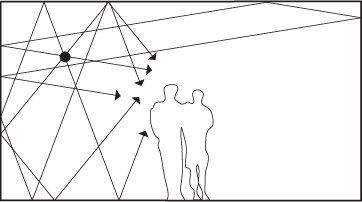
Glare
Direct glare stems from light sources that are directly visible in the visual field. It can result from daylight, sunlight, artificial light or specular surfaces. It is known that glare limitation prevents errors, fatigue, accidents and discomfort arising from high contrast levels – the eye can adapt to lower levels of light so long as these are uniformly spread throughout the space.
Modeling Daylight
The combined facilities of an artificial sky and a heliodon can act together as a physical simulator to model daylight and sunlight penetration into a building or across a site. An artificial sky comprises a hemispherical dome that supports an array of individually controlled fluorescent luminaries. It can model all types of sky conditions around the world. A heliodon can model the sun’s path in relation to a site for any time or location around the world.

1 Calculating the overall daylight factor for a room.
2 Beams of light are created by tiny dust particles.
3 By placing a model building on a heliodon’s flat surface and making adjustments to the light/surface angle, it is possible to see how sunlight would penetrate the building and cast shadows at various dates and times of day.
4, 5 Example of an artificial sky.
Direct heating systems involve the use of stand-alone appliances in each room of a building. From open fireplaces or woodburning stoves to electric fires and gas convector heaters,* such appliances require their own direct fuel supply or energy source.
Indirect Heating
Known as central heating, indirect systems rely on a single source – a furnace, solar system, or boiler – to generate heat. This heat is then distributed throughout the building by a heat transfer mechanism – pipes for water or steam (wet indirect heating), ducts for air (indirect warm air heating).
Hydronic Heating
In a conventional radiator system, boilers burn fuel such as gas or oil in order to heat the water contained within them to region of 176°F. The water is then pumped around the building. Heat emitters – surfaces – are used to transfer heat from the supply pipes into rooms by convection and radiation. The surface (radiator) is sized according to the volume of the room, and its temperature can be controlled by a “thermostatic” valve that automatically controls the flow of water according to the room temperature.
Convection can be enhanced by encasing the radiator and allowing the air inside to heat up: cool air enters via a lower grille and warm air exits at the top. A fan can be added to drive the circulation of the air.
Underfloor heating
Floors and walls themselves can be turned into heat emitters by embedding loops of (polyethylene) water pipes. These can operate at substantially lower flow temperatures than conventional radiators due to the large surface areas and, thus, are ideal for the application of solar thermal water heating. Underfloor heating can also be provided by electrical heating elements but this is a very energy inefficient solution.
Indirect Warm Air Heating
A centrifugal fan is used to pass air over a heated surface (usually coils of hot water pipes) and then through ducts into rooms. The air may pass through a filter and may be recirculated through a separate duct using a smaller fan. These systems warm rooms up more quickly than wet systems and may also be used for ventilation purposes.
Indirect warm air heating is the standard in the United States. These systems have the advantage over radiant systems in that they can change the air temperature in a space very quickly and may also provide fresh-air ventilation. Occupants, however, generally do not find the space conditions created by warm-air heating as comfortable as those conditions created by radiant systems.
*Gases that are the product of the combustible fuels used in boilers and gas convector heaters are known as flue gases and require a separate outlet. When gas is burnt in air it produces, among other things, carbon monoxide which is an asphyxiant and must be safely removed from the building through a vertical duct known as a flue. Areas where boilers are kept must also be well ventilated.

1 Hydronic heating system.
Building Services / Mechanical Ventilation
Indoor air quality (IAQ) has become a major source of concern in the design of buildings. Sources of indoor pollutants include carbon dioxide from building inhabitants, volatile organic compounds off-gassing from building materials, odors from bathrooms and cooking, and moisture from indoor sources. In tightly built modern buildings, these undesirable elements must be removed and fresh air provided to ensure the health, comfort, and productivity of building occupants.
Extract Ventilation
In both domestic and commercial buildings, rooms that generate high levels of moisture or odour, such as kitchens and bathrooms, should have a means of extracting stale air. In bathrooms, this is generally accomplished with an exhaust fan and in kitchens and laboratories with a ventilation hood that ducts the air to the outside.
Supply Ventilation
Buildings should ideally have a regular supply of fresh air provided to the occupants to ensure adequate IAQ. The simplest means of supplying fresh air is via supply ventilation or make-up air. Instead of sucking stale air out of a building, fans are used to force air into it. The effect is to pressurize the internal spaces and drive the stale air out.
Balanced Ventilation
As buildings have become tighter, and energy use a greater concern, the use of balanced ventilation has emerged as the preferred strategy for providing fresh air and removing indoor pollutants.In a similar process to indirect warm air heating, combining supply and extract ventilation in a single circuit allows the system to provide a constant supply of fresh air to a space. If the supply air is cooler than the air inside the building, heat can be recovered from the warm, exhausted air by passing it over a heat exchange element.
Humidity Control
Certain levels of humidity have to be maintained in a building, because of their impact on its fabric and the different types of material being stored within, for the comfort of its human occupants and to control molds and allergens that become active at high humidity levels. An average house produces some 26 pints of water vapor per day and when warm moist air comes into contact with a cooler surface it condenses. This condensation then causes materials to decay, e.g. timber to rot, steel to rust. Encouraging natural air movement through buildings will help to reduce the potential for condensation. Mechanically, humidity levels can be raised using humidifiers or lowered using dehumidifiers. As with heating and cooling, these mechanisms may be applied directly within rooms or within the air handling unit of an air-conditioning system.

1 Ventilation system.
Building Services / Air-Conditioning: Principles
Air-conditioning describes a number of systems for modifying the climate within buildings. Usually, it is concerned with cooling, but centralized systems can also provide heating, air filtration,* humidity control and ventilation.
Vapor Compression Cycle
Electrically powered chiller units work on the same principle as a domestic fridge. For a liquid to evaporate it must absorb energy. By passing a refrigerant (a liquid that evaporates easily at relatively low temperatures) through a coil, it removes energy from the coil by taking heat from the air around it: thus the air is cooled. The vaporized refrigerant is then condensed using a compressor and passed through a second coil where the (waste) heat energy released by the condensing process is again passed to the air.**
Absorption Chilling
Absorption chillers use heat instead of mechanical energy to provide cooling. In absorption chilling systems, the mechanical vapor compressor is replaced by a thermal compressor. The process is based on evaporation, carrying heat in the form of hot molecules from one material to another that absorbs them (similar to human sweating where water from sweat evaporates and is “absorbed” into cool dry air, carrying away heat in water molecules). Absorption chilling works in practice by evaporating liquid ammonia and dissolving the vapor in water. This solution is pumped to a generator where the refrigerant is revaporized; the solution is then returned to the absorber.
* Air carries all sorts of suspended particles, from dust and fibers to microscopic bacteria and viruses. With centralized air-conditioning, these particles must be filtered on entering and leaving buildings and periodically cleaned from ducts and from the air handling units. Filters are made from a variety of fabrics of differing porosity and may be impregnated with (anti-microbial) biocides, employ electrostatic attraction or use carbonaceous material to filter gaseous pollutants.
** A heat pump employs a vapor compression system for heating rather than chilling. The cool air is delivered to the outside and the warm air is used for space heating. Reverse cycle heat pumps can provide both heating and cooling as and when required; they can be used very efficiently to transfer thermal energy from the warmer parts of a building to the cooler parts.

1 Vapor compression cycle.
2 Absorption chilling.
Building Services / Air-Conditioning: Systems
Evaporation Cooling
An evaporative cooler (often called a swamp cooler) is essentially a large box- like frame containing a big fan that drives the hot outside air through pads that are continually soaked by a water pump. This cools the air by about 20°F as the air evaporates water molecules from the pads. The fan then blows the water-cooled air through the building. In hot dry climates, evaporative cooling is a very energy-efficient and cost-effective solution. It is not suitable for humid climates because of the excessive moisture vapor already in the air.
Unitary Systems
Both the evaporator and condenser are contained within a single unit in a unitary air-conditioning system. This type of system can range from the window unit to a ducted rooftop system. Window or through-the-wall units knowns as packaged terminal air conditioners (PTAC) provide local cooling to the space in which they are located. A fan draws air from the room, through a filter, and over the evaporator coil before discharging it back to the room. Outside air is drawn over the condenser coil to remove waste heat. Local cooling units are generally less efficient than larger systems, but can sometimes result in less total energy use since they may target only a specific space that needs cooling at a given time.
Ducted unitary systems (often referred to simply as package units) work similarly, but with greater capacity and can distribute air through ducts to remote locations. Package units are most often mounted on the roof of a building and discharge air downward into the space.
Split Systems
In a split system, the condenser is located outside and the evaporator inside while refrigerant is piped back and forth between them. This is the most common design for residential air conditioning systems in the Unites States. Inside air is filtered (and mixed with a proportion of tempered fresh outside air in the better systems), drawn over the cooling coil, and returned to the space via ducts. The outside unit discharges the heat absorbed from inside by the refrigerant to a heat sink, most often outdoor air. A central air-conditioning system can provide heating, cooling, air filtration, humidity control, and ventilation through one central air-handling unit that blows conditioned air through ducts to the entire zone that it serves. Air typically returns at a single point to the air handler to be circulated once more. Most residences consist of only one zone, but larger buildings may have many.
Mini-split Systems
In most cases, mini-split systems work much like a conventional split system, except that the inside unit is not connected to ducts. Such a system takes air in and discharges it from the evaporator unit itself relying on velocity and convection to distribute it through the space. An advantage of these systems is that 4 or more evaporators may be connected to a single condenser unit up to 150 ft away, providing an effective solution for zoning the building so that individual spaces may be conditioned only as necessary.
The evaporators for mini-splits may also be concealed in a ceiling or connected to short duct runs.
Geothermal Heat Exchange
If available, other media make much more efficient heat sinks than outdoor air. Bodies of water such as ponds, swimming pools, lakes, and seas provide excellent heat sinks (or sources in the heating season) where heat absorbed by the refrigerant may be discharged by the condenser. The earth is also an effective heat sink/source in climates with relatively balanced heating/cooling seasons, but it is usually quite costly to bury adequate piping to make use of the geothermal stability of the earth’s underground temperature.

1 Centralized air-conditioning system.
2 Air-conditioning fans.
3 Active/passive cooling systems. Natural air flow is enhanced by mechanical fans and exhausts. However, the cool temperatures found below ground are employed to cool the incoming air.
Building Services / Integrated Systems
In terms of the environment, the aim of all construction projects is to minimize the amount of carbon emissions both during construction and for the life of the building. This means exploring both the sourcing and transportation of materials and the construction process itself – the embodied carbon in a building – as well as its long-term environmental strategy.
In practice, most buildings employ environmental strategies that combine both passive and active components, viz.:
Natural ventilation
Natural ventilation can be optimized by automatically opening and closing windows, rooflights and/or dampers via an integrated energy management system, however, while opening a window does provide ventilation, the building’s heat and humidity will then be lost in the winter and gained in the summer.
Mechanical ventilation
Where mechanical ventilation is used to solve this problem, it can be integrated with air conditioning and evaporative cooling systems to cool below ambient temperature* or with heating and heat recovery systems to raise internal temperatures.
Solar shading
Automated louvres can reduce cooling loads in summer by preventing solar heat gains and reduce heating requirements in winter by closing to reduce heat loss at night time. Photovoltaic cells may be integrated so as to generate electricity.
Ground source heat pump
Since the temperature below the top 20 ft of the earth’s surface is nearly constant at between 50° and 60°F, a ground source heat pump uses the earth as a heat source in the winter or a heat sink in the summer by employing a heat exchanger in contact with the ground. The simplest method pumps refrigerant through coils or loops of copper tube that are buried in the ground.
Combined heat and power
Combined heat and power (CHP) systems make use of the exhaust heat (e.g. steam) from electricity generators by capturing it and feeding it back for heating or hot water. Most often used in district heating, where for reasons of efficiency heat is generated in a central location for a number of buildings (rather than each having its own boiler).
*Combined evaporative cooling and ventilation systems only require a small quantity of electricity for the fan that circulates the air. They are particularly effective in large spaces – industrial or commercial buildings, such as warehouses – where a pure ventilation system is unable to provide a suitable internal climate.
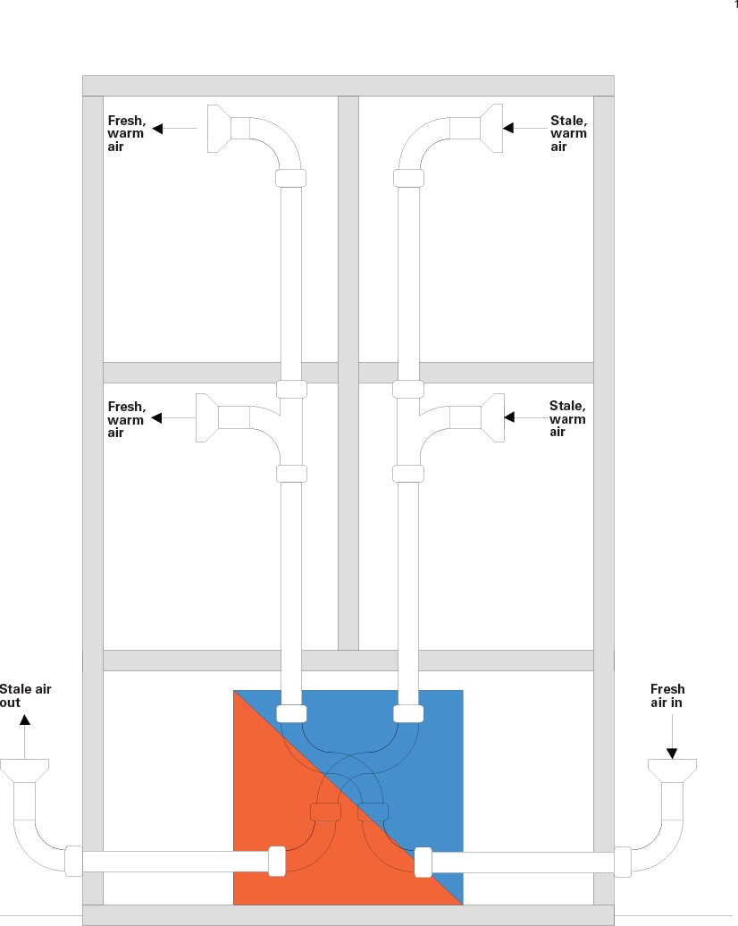
1 Heat Recovery Ventilation systems (HRVs) introduce fresh air to a building, and heat it using the warm air that is being removed.
Building Services / Sanitation
The World Health Organization states that: “Sanitation generally refers to the provision of facilities and services for the safe disposal of human urine and faeces.”
In practice, architects are concerned with sanitation in relation to the organization of both the supply of clean water and the disposal of wastewater, as well as the provision of refuse and recycling amenities.
Supply
Water supplied directly to buildings from reservoirs via (normally underground) piping is commonly known as running water or simply tap water. Depending upon the source, this may or may not be drinkable. Water for cleaning (as opposed to drinking) may also be supplied directly from rainwatercollecting cisterns or via on-site holding tanks.
Wastewater collection
In urban areas, the collection of wastewater is normally via sewers for treatment in wastewater treatment plants (for reuse) or for disposal in rivers, lakes, or the sea. Sewers in older, urban areas are often combined with storm drains, and heavy rainfall can lead to raw sewage being discharged into the environment.
In suburban and rural areas, households that are not connected to sewers discharge their wastewater into septic tanks (cisterns) or other types of on-site sanitation. Depending upon space and ground conditions these can either be sealed containers that are periodically emptied or caissons (watertight retaining structures) that permit the effluence to degrade and soak away into the ground below (paper is disposed of separately).
Gray water
Gray water is wastewater that does not contain faecal pathogens. If composting toilets are employed to provide for the separation of urine and faeces at source, all wastewater will consist only of gray water, which can be recycled for gardening or safely discharged into sewers.
Above-ground waste
Traditionally waste pipes were made from metals such as cast iron, lead and copper, though these days pipes are made from a variety of plastics and in standard sizes of 10 mm (¾ in) to 110 mm (4⅓ in) diameter according to function. The most widely used are: ABS (Acrylonitrile Butadiene Styrene), MuPVC (Modified Unplasticized Polyvinyl Chloride) and PP (polypropylene).
To prevent sewer gases from entering buildings, a U-shaped pipe (or similar) is always connected between the fitting (bath, sink, toilet, etc.) and the waste pipe. Known as traps, the U-bend always retains a small amount of water and creates a seal that prevents sewer gas from passing from the drain pipes back into the building. Toilet pans have built-in traps. Waste pipes carrying urine and faeces (known as soil pipes) must be independently vented to beyond the roof line (a soil stack).
Drainage systems
Below ground, the waste pipes must connect to drainage systems that in turn are connected to a sewer or other wastewater receptacle. Drain pipes can be made from a variety of materials (most commonly, clay, PVC-U, polypropylene or a type of synthetic rubber known as EPDM) in sizes ranging from 100 mm (4 in) to as much as 600 mm (23½ in) in diameter for major sewers.
A critical part of all wastewater systems is the ability to access, inspect and maintain the pipework both above and below ground, and hence the architect must make provision for access panels, manholes, etc. as appropriate.

1 Typical domestic supply and waste diagram.

Finite element analysis (FEA) of an anticlastic shell structure.

Form finding – recombining 3D “hyper” shapes.