
Covering the fundamental principles of structural form
Materials Science
In order to understand how buildings work as structures, it is necessary to appreciate the natural laws that govern structural form. This involves an understanding of the forces that act upon materials and the ways in which the materials will react to those forces according to their fundamental properties. Materials Science covers: forces – how, through gravity, materials are subject to stress and strain; properties of materials – how materials can be analyzed and manipulated for strength and stiffness; and reactions – how components behave when subjected to forces through bending and shear.
Materials Technology
While materials science is the study of the interplay between the properties, structure, and changes in solids, materials technology is the utilization of this knowledge in the production and fabrication of materials and structural components. Most fabrication processes involve a series of primary ways of acting on materials – cutting, sawing, bending, welding, etc. – with the precise nature of the process determined by the properties of the material to which it is applied. In general, the ability to move raw materials and finished products around factories, building sites, and indeed around the world, places finite limitations on the size, shape and weight of prefabricated building components. Materials technology explores a range of common building materials: stone, timber, steel, reinforced concrete, glass, fabric, fiber-reinforced plastic, and sheet materials.
Structural Integrity
Knowing the behavior of the materials and components that go to form structures enables the architect to organize them in such a way that the whole structure will be rigid and stable under load. Structural Integrity examines the types of load to which buildings are subjected – live and dead loads, lateral loads, bracing, and torsion – and how structures may be constructed to resist them through triangulation and bracing. Overall stability, as in the rooting of a tree, is then considered in the context of the center of gravity and the cantilever (or branching) principle.
Materials Science / Forces: Stress, Strain
Structural engineering is concerned with calculating the ability of structures and materials to withstand forces. When you talk about the weight of an object, you are actually describing the force that the object exerts as a result of gravity acting on its mass. Gravity is responsible for attracting all objects towards the center of the earth. Over 300 years ago, Isaac Newton discovered that this gravitational “pull” (indeed, all forces) produce an acceleration of the system or object that they are acting upon, hence:
FORCE = MASS (lb) x ACCELERATION (ft per sec., squared)
Force is measured in Newtons:
1 Newton = 1 kg x 1 m/sec²
(2½ lb x 3 ft 3 in/sec²)
Gravity is calculated as:
g = 9.81 m/sec² (g = 32 ft 2 in/sec²)
Structural Form
All objects have an underlying structure that maintains the form of the object when it is subjected to forces. The forces act upon the object, and the object reacts according to the properties of the materials from which it is made and the way in which they have been shaped and assembled. Stress is the term used to describe the forces acting on a material or structure; strain is the term used to describe the material or structure’s response to those forces.
Stress
Forces can act on materials in one of two fundamental ways: they can push, which is a compressive force, or they can stretch or pull, which is a tensile force. These applied forces are described in physics as stress, which is measured as the force per unit area across any given cross-section of the material:
f (STRESS) = P (FORCE) / A (AREA)
Strain
Materials use their internal structures to resist forces. Every material reacts to stress by distributing it in such a way that there is an equal balance of internal forces. The result is strain – a change in the form of the structure, measured as the fractional extension perpendicular to the cross-section. Hence, compression may be described as stress that acts to shorten an object and tension as stress that acts to lengthen it.

1 Compression
Bulgarian weightlifter Glagoi Blagoev’s body is put into compression by the weights held aloft (approximately 430 lb or over twice his own body weight).
2 Compression
When force is applied to the top of the structure indicated by the arrow, the sides of the structure are put into tension (T), forcing the cross section to increase.
3 Tension
A tug of war puts the rope into tension over its length, forcing the sides of the rope into compression and thus reducing the cross-section of the rope. The ratio of cross-sectional contraction and linear extension is described as a Poisson ratio.
4 Tension
When most materials are put into tension, their cross-sectional area is put into compression (C) thus reducing the cross section.
Materials Science / Properties of Materials: Strength, Stiffness and Flexibility
Properties
Every material has its own internal structure that predisposes it to resist forces to varying degrees and to react to them in different ways. It is this behavior – this reaction to forces – that gives a material its inherent structural properties. Some materials, for example, will tear easily but can be pulled (like paper), and some can be pulled but not compressed (like string). Some, like concrete, are strong in compression but weak in tension and others, like steel, are strong in both tension and compression.
Plastic-Elastic Behavior
As it resists forces a material will react by deforming its internal structure. With plastic materials the internal structures readily deform and adapt to a new shape when stressed. A plastic material distorts easily but does not break (an example is lead). With elastic materials the internal structures remain the same but are warped or stretched; they always remember their original shape and want to return to it. An elastic material returns to its original length (or shape) when the stress is removed (an example is bamboo).*
Strength
While a fishing rod is not strong, it is very elastic – it will bend a great deal before it snaps. It is the ability of an elastic material to resist bending (elastic deformation) that will determine its strength. All materials have an elastic limit – if you stretch them far enough, they will fail. They will either warp or buckle, or they will break – fracture or tear. A strong material is one with a high breaking stress, a weak material one with a low breaking stress.**
Stiffness and Flexibility
A stiff material needs a large force (stress) to produce a small extension (strain) – it is difficult to change its shape. A flexible material only needs a small stress to produce a large extension – it is not difficult to change its shape.
* Materials with low plasticity are prone to breaking or fracturing under stress – are brittle – and are likely to become more so as temperatures decrease. Highly plastic materials deform without breaking or fracturing – are ductile – and are likely to become more so as temperatures increase. Heating metals increases their plasticity.
** Standard structural steel will fail at around 30 ksi, while wood will reach its ultimate stress at around 1.0 ksi or less depending on species and grade.
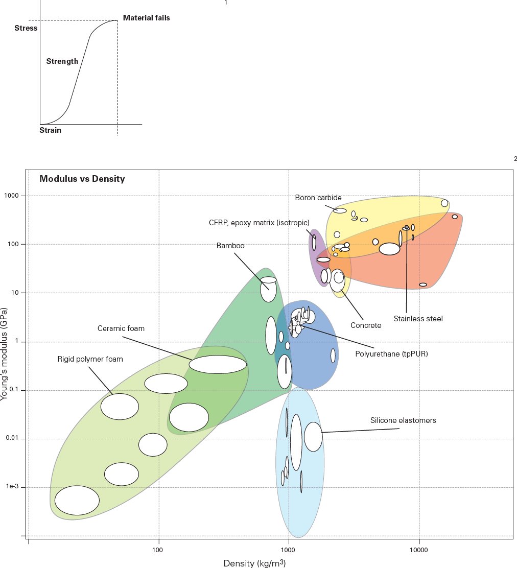
1 The strength and stiffness/flexibility of a material, as determined by its resistance to (elastic) deformation, can be measured as the ratio of stress to strain. When plotted on a graph, the (stiffness) values are known as the Young’s Modulus. Young’s Modulus is used to measure increases in a material’s length when it is put under tension or to predict the buckling or yield point. Generally, as density increases so does Young’s Modulus but there are exceptions to the rule.
2 The chart shows the relationship between categories of materials in respect to the Young’s Modulus and the density of the material. Published by Granta Design, this type of chart was pioneered by Professor Mike Ashby, Cambridge University Department of Engineering. These charts manage to condense a huge range of analytical data into a graphically legible format within which the comparative properties and groupings of materials can clearly be visualized and assessed.
Materials Science / Reactions: Bending, Shear
Bending
Bending is the result of a material deforming itself under stress. In diagram 1, the beam at the top is subjected to an external, compressive force that in turn creates internal strain through bending (exaggerated in the diagram): the top side becomes compressed – shortened – and the underside becomes tensioned – lengthened. The lower diagram describes bending in a truss, showing the reactions of the individual components: red are in tension, blue in compression.
In diagram 2, bending has been exaggerated by the insertion of cuts and wedges in the beam. Once loaded, the wedges in the upper side will be compressed and close up, while the cuts in the lower side will be pulled apart to form wedges. Excessive bending will cause failure.
Shape and Form
When materials are formed into structural elements, the distribution of stresses is modified by how they are shaped and formed – the deeper a beam, the further apart are these internal forces and the more even the distribution of stresses. Diagram 3 illustrates the effect of cross-sectional shape on bending.
Shear
Unlike tension and compression, where surfaces move towards or away from one another, shear refers to deformation in which parallel surfaces slide past one another, as shown in diagram 4. Shear stress is a stress state where the stress is parallel or tangential to a face of the material, as opposed to normal stress when the stress is perpendicular to the face. In structural and mechanical engineering the shear strength of a component is important for designing the dimensions and materials to be used for its manufacture.
With an I-beam for example, the flange resists bending and the web resists shear. See Beam: Cross-Sections, page 44.

1 Effects of bending in a beam. The arrows on the top edge of the diagrammatic beam indicate the direction of forces under deflection. Similarly the top chord and the vertical members of the diagrammatic truss are put into compression under deflection (shown in blue), whereas the bottom chord and diagonal members of the truss are put into tension.
2 Effects of bending in a beam. A “notched” beam illustrates the expansion-contraction or compression and tension experienced by a beam under loading.
3 Effects of cross-sectional shape on bending. The orientation of structural members and their cross-sectional shape vastly affect their performance under loading. The pair of diagrams on the left illustrate how the orientation of a simple structural member can affect its loadbearing capacity. The increased depth that the orientation in the lower diagram shows vastly improves its structural performance. The drawings on the right show how an increase in cross-sectional profile stiffens a vertical member under load.
4 Shear forces act tangentially or parallel to a material face, rather than perpendicularly.
Structural Integrity / Loads: Live and Dead Loads, Lateral Loads, Bracing, Torsion
To create structural form, building components are sized, shaped, and arranged in such a way that the structure as a whole is able to resist the forces acting upon it. At this scale, a distinction can be made between the forces that arise through the mass of the structure itself – a constant force known as a static or dead load – and external forces that move or change, known as the dynamic or live loads. In buildings, live loads consist of furniture, machinery, occupants, and snow and ice, as well as, crucially, the lateral impact from wind.
Lateral Loads
A chair must be strong enough to resist the vertical load of its occupant. However, as the occupant shifts their load – to lean, wobble, or sway – the chair must remain rigid. This is because it is designed to resist these nonvertical loads through a combination of the stiffness of its components and the rigidity of the whole structure. This rigidity is, in effect, an equalizing of the vertical and horizontal forces throughout the structure by the use of diagonals – i.e. through triangulation.
Bracing
Take a simple, square frame. If you add a force to one side of it, it will deform (shear). If, however, you were to put a stick from one corner to the other, the square would remain stable. If you pushed on the other side of the square, the stick would still work but only if it was connected at both ends, as it is transferring the load by being pulled. In the first case, the stick is used as a compressive element; in the second, it is in tension and could be replaced with string or wire.
Torsion
Structural components may also have to be braced so as to prevent them twisting. Though sometimes referred to as a force in itself, torsion or twisting is in fact the result of opposing (tensile or compressive) forces acting in a rotary fashion.

1 Bracing in a steel-framed structure.
2 Principle of bracing. A square frame is an inherently unstable structure because of its lack of bracing. An applied force as indicated by the arrows will transfer the structure into a skewed diamond shape unless either a rigid (compression element) or a linear (tension) element is introduced diagonally across the frame to triangulate or “brace” the structure.
3 The key to bracing is triangulation, and even in a simple table there are small, “invisible” triangles bracing the structure.
4 “Pinwheeled” structure: this is an idealized structure where each of the legs or columns is widened to brace the structure and are then rotated so that the structure is able to resist forces from any direction.
5 Principle of torsion or twist, which can be resisted by the cross-sectional profile.
Structural Integrity / Stability: Anchorage, Height, Center of Gravity, Cantilever Principle
Anchorage
Buildings have to be braced in order to resist wind loads and, in more extreme circumstances, a sudden impact or vibration such as from a wave or earth tremor. Not only must the mass of a structure not deform under lateral loads, it must also not move as a whole. Buildings are anchored to the ground with foundations that also provide a bearing in unstable or soft ground.
Wind also produces internal pressure and suction on external surfaces. Roofs in particular need to be securely anchored to the main structural elements.
Height
Tall structures have to withstand not only high-speed gusts of wind, but also the vibrations that wind can induce (similar to those of a tuning fork). Tall buildings are designed to resist these forces by having a rigid, central core with floor plates that are carried from perimeter columns and connected back to the core. The core is also used to contain elevators, staircases and service ducts. Tall structures may also be stabilized by employing diagonal struts wrapped around the outside of the building in a criss-cross fashion; when used without a central core, these are known as tube structures.
A dense honeycomb of internal walls will also improve structural stability.
Center of Gravity
Try leaning forward from the hips. At some point your center of gravity goes “outside of you,” and one leg moves forward to form the triangle that keeps you from toppling over – keeps you stable. Carry on bending, and you will reach the point when the only way to maintain your center of gravity is to extend your other leg behind you. This is a process known as “cantilevering”.
Cantilever Principle
A cantilever is a description of an element that projects laterally from the vertical. It relies on counterbalance for its stability and on triangulation to resist the bending movements and shear forces of the lever arms.

1, 2 Reinforced-concrete cores provide stability for framed buildings.
3 The designers of the Forth Railway Bridge, Scotland used their own bodies to demonstrate how the span of the bridge uses the cantilever principle. The bodies of the two men at ground level are acting as columns (in compression), and their arms are being pulled (in tension). The sticks they hold are in compression and are transferring the load back to the “columns”.
4 The Forth Railway Bridge with girder spans of 521 m, completed in 1890. Fife, Scotland.
5 Cranes displaying the cantilever principle.
6 Cantilevered brackets are employed to support a roof canopy at the Royal Ascot Racecourse, Windsor, UK by HOK Sport.
Stone is a low-tensile material, i.e. it is strong in compression but weak in tension. Traditionally used to form loadbearing walls, columns and arches, it can be also be carved into lintels or beams, but since the material has little tensile strength and is dense and massive these spans tend to be of limited size.
The oldest of the building materials known to man, stone is still one of the few that is transformed into a product at source. It is excavated both from underground quarries accessed from shafts and by the opencast method where it is cleaved from the rock face using mechanical excavators. Different layers of rock (beds) produce different sizes, qualities, and types of stone, and this will determine the way in which it is acted upon. Stone can be sawn, cropped, split or chiselled into shape, although this material often has a grain which must be considered when maximizing its structural properties.
Stone blocks direct from the quarry are either cropped to size using a guillotine or sawn into shape using a range of mechanical saws. A multi-bladed frame saw will carve a block of stone into a set of slabs in roughly six hours. A diamond-bladed circular saw enables precision cutting as the blade follows a laser line, can operate in various axes, and is also used to mill or route precise geometric incisions from the surface of the stone. These tools can be instructed from computer-aided-design (CAD) files.

1 Diamond-bladed circular saw cutting a stone block.
2 Limestone quarry, Dorset, UK.
Wood in construction is most broadly categorized as rough lumber or finished lumber and as hardwood or softwood. Rough lumber is used for structural purposes while finished is exposed in the final product.
Hardwood and Softwood
Hardwood comes from deciduous trees and softwood from coniferous ones. Softwoods are used in most wood structural systems, light framing being the most common. The more rarely used heavy timber framing is usually also from softwood species.
Both hardwoods and softwoods are used for finished lumber. Lower quality finished lumber is often used when the surface may be patched and painted, while the higher quality material is used in applications where the wood will receive a clear finish.
To be used in construction, wood must be dried either in open air or in a drying kiln. Even after this process, the wood often contains enough moisture that it will continue to dry on the construction site. As wood dries, it shrinks.
Engineered Wood
Engineered wood uses wood fiber recombined using glue, making a stronger product than solid wood. The most familiar engineered wood product is plywood, where thin veneers of wood are glued together in layers. Oriented strand board (OSB) frequently replaces plywood today as it instead uses chips of wood pressed and glued into a sheet. Engineered wood has also found applications in finished products, especially flooring.
Preservatives
When it is exposed, too much or too little moisture will cause wood to rot and become prone to fungal and insect attack. Except in the case of a few rot-resistant species, exposed wood must be painted, coated, or pressure-treated. Pressure treatments impregnate the wood with chemical preservatives and must be used where the wood is in contact with the ground or with concrete.

1 Lumber from the logging mill: rough sawn.
Steel is a product of coal, iron ore and limestone, and is manufactured in a number of stages. The coal is rid of its impurities – transformed into coke – and mixed with iron ore and limestone in a blast furnace to produce liquid iron. This is known as pig iron and when solid it is strong but very brittle. To convert this into steel (which is strong but flexible) the proportion of carbon in the mix must be adjusted by blowing hot air or pure oxygen into the molten iron. Steel used for construction purposes is standard carbon steel, which has up to 0.3 per cent carbon and is known as mild steel. The liquid steel is then cast into billets that are the stock from which structural shapes are made.
Hot-Rolled Steel
Most of the steel used in the construction industry has been extruded through a profiling machine. In the hot-rolling process, the steel billets are re-heated as they are forced through a series of rollers to produce sections such as wide flanges, channels, angles, and bars. Steel sections can be curved by rolling. Sections can be connected by drilling and bolting (a process that can permit tolerance – for adjustment – or disassembly) or, for a permanent fusion, by welding. It is possible to create a fully welded joint that will fuse two pieces of steel so that they perform as one.
Most hot-rolled steel sections are specified according to their sectional designation, normal size, and weight per foot. For example, a W 8 x 28 is a wide flange approximately 8 in high that weighs 28 lb/ft. Hot-rolled sections are generally used for columns and beams.
Cold-Rolled Steel
Structural steel sections can also be formed by “rollforming” flat steel coil in a machine. Such machines are capable of producing a range of steel profiles out of 1⁄16-⅛ in thick steel coils. Cold-rolled sections are generally used for repetitive members that carry lighter loads
Corrosion
Corrosion is the deterioration of the essential properties of a material due to its exposure to the environment. It normally refers to metals reacting electrochemically with water and oxygen, as with the oxidization of iron atoms to produce rust. Iron or steel can be prevented from rusting in a number of ways: through surface treatments such as plating, painting, or the application of enamel or reactive coatings, or by galvanization – the process of coating iron or steel with a thin layer of zinc that protects the steel from rusting. Steel is either passed through molten zinc (hot-dip galvanizing) which oxidizes to form a surface layer, or zinc is deposited on the surface by electroplating (electrogalvanizing).

1 A range of hot-rolled steel sections.
2 Steel staircase fabricated from steel angles and flat “plate” strips.
Materials Technology / Reinforced Concrete
Formwork
Formwork is the name given to the mold from which concrete is cast. Formwork is usually built with dimensional lumber and plywood, but many prefabricated formwork systems are also available. Releasing agents are applied to the surface of the formwork before the slurry is poured. As it is placed, the concrete must be compacted by vibration in order to remove air bubbles.
Reinforcing
Concrete can be cast either on site – in situ – or in a factory – precast. In either case, although concrete is very strong in compression, the material must be reinforced with steel bars for it to withstand tensile stresses. The size and distribution of the stresses within the concrete are modified by the steel bars. The bars are formed into a cage which sits in the lower part of the beam where the tensile stresses are at their greatest.
Prestressed Concrete
For spans of over 26 ft 3 in it is advisable for the reinforcing bars to be tensioned. The principle behind prestressing is similar to that of lifting a row of bricks horizontally by applying pressure to the bricks at the end of the row. When sufficient pressure is applied, compressive stresses are induced throughout the entire row, and the whole row can be lifted and carried horizontally. With concrete, this can be done either by pretensioning or post-tensioning the steel reinforcement.
In pretensioning, the steel is stretched before the concrete is poured. Once the concrete reaches the required strength, the stretching forces are released and, as the steel reacts to regain its original length, the tensile stresses are translated into a compressive stress in the concrete. In post-tensioning, the steel is stretched after the concrete hardens. The concrete is cast around ducts or tubes, and once the concrete has hardened to the required strength, steel tendons are inserted into the tubes, stretched against the edges of the concrete, and anchored off externally, placing the concrete into compression.
Self-Compacting Concrete
Self-compacting concrete is a fluid concrete that will flow freely into molds and around steel reinforcement and will fully compact without the need for additional vibration. It contains additives that are known as plasticizers. Similar to washing-up liquids, plasticizers allow less water to be added to the concrete mix, making it stronger and ensuring an even distribution of the binder and aggregates. They also leave a glasssmooth surface both when the concrete is poured horizontally and when it is placed in formwork.
Concrete is made from a binding material combined with aggregates and mixed together with water to create moldable slurry. The binder consists of cement, granulated blast furnace slag or pulverized fuel ash, and aggregates consists of natural materials such as gravel, sand, and stone chippings.
The usual proportions are: 6 fine aggregate (e.g. sand) 1 coarse aggregate (e.g. stone) 1 binder (e.g. Portland cement)
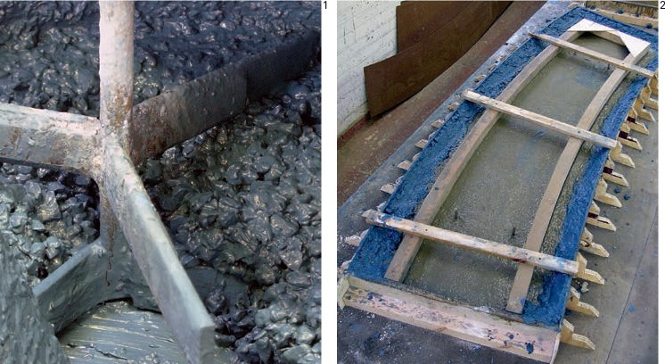
1 Wet concrete (slurry) in a mixing machine.
2 Precast concrete component: casting colored concrete in a mold.
Float Glass
Float glass is a sheet of glass made by floating molten glass on a bed of molten tin. This method gives the glass uniform thickness and very flat surfaces. Modern window glass is float glass.
Float glass is made by melting raw materials consisting of sand, limestone, soda ash, dolomite, iron oxide and salt cake. These blend together to form a large pool of molten glass. Standard float glass comes in thicknesses ranging from ⅛ to 1 in, and in panes of up to a maximum size of 10 ft 6 in by 19 ft 6 in.
Glass used for structural purposes has been toughened in one or more of the following ways:
Annealing
By controlling the rate at which molten glass cools, the stresses and strains that normally occur due to uneven shrinkage during cooling can be removed from the glass.
Tempering/Toughening
Glass is re-heated and the surfaces are then rapidly cooled with jets of air. The inside core of the glass continues to cool and contract, forcing the surfaces into compression and the core into tension. When the glass breaks the core releases tensile energy, resulting in the formation of small glass particles.
Laminating
Layers of glass are bonded together with a resin interlayer to form a composite panel. If an outer layer breaks it is held in place by the substrate.
For safety reasons, structural glass beams typically consist of three layers laminated together. Beams are connected to columns using bolts and/or silicon glue. Structural glass is also used for ribs or “fins” that are fixed perpendicular to panes in order to resist wind load on glass façades.
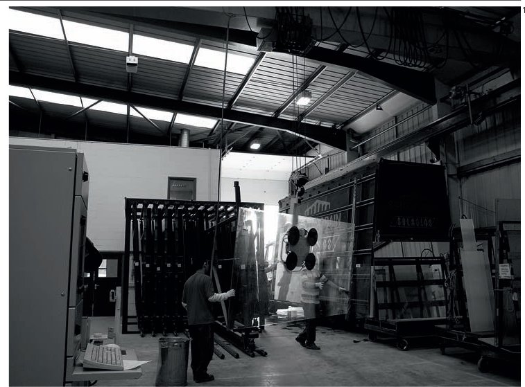
1 Float glass being moved around a factory.
Materials Technology / Fabrics
Polymerization is the last in a series of chemical processes needed to create the molecular chains that form polyvinyl chloride (PVC). PVC is a thermoplastic and is produced in the form of a white powder that is blended with other ingredients to form a range of synthetic products. Additives include heat stabilizers and lubricants as well as those that determine mechanical properties such as flexibility.
Membrane fabrics are made from PVCcoated polyester. These synthetic fabrics are strong in tension and resistant to shear and there is a range of around 20 standard colors. They are light, flameproof and have a maximum thickness of about 1⁄16 in. Ultraviolet light and weathering will cause deterioration in the fabrics over a period of between 10 and 20 years depending on the climate. Membrane fabrics can be used for roof canopies (see Tensile Surfaces, page 68) or, when pressurized with air, can be formed into structural elements such as air beams.
Air is not the only gas that can be used for pressurization. When a gastight fabric is inflated with hydrogen or helium it will form a buoyant (lighter than air) structure such as an airship.
The process of fabricating membrane structures is akin to that of tailoring. The fabric is delivered in rolls anything up to 7 ft 10 in wide, and panels can be cut by automated cutting machines according to computer-aided-design (CAD) profiles. These computer numerically controlled (CNC) cutters have a variety of interchangeable heads (consisting of a hole punch and cutting wheel) while the 69 ft benches along which they travel are designed to vacuum the fabric onto the cutting surface for precision cutting.
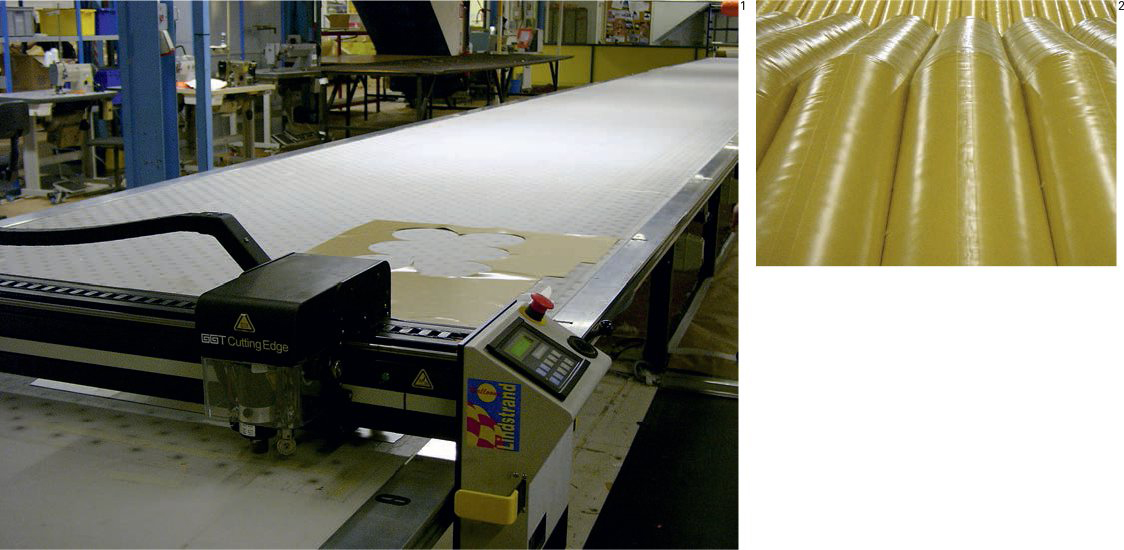
1 The design of pressurized or tensile membrane structures involves patterncutting techniques similar to those used in tailoring.
2 These polyester “air beams” have been stitched and welded together to form a continuous surface.
Materials Technology / Fiber-Reinforced Plastic
As with any pouring or molding process, the act of casting shapes out of fluid materials has the advantage that complex, curved surfaces may be achieved. Large-scale structural components are now commonly manufactured out of resins that are reinforced with fiberglass. The fiberglass is built up in layers inside the liquid resin – a process known as laminating – and products are often further reinforced with layers of foam, Kevlar or carbon fiber for extra stiffening.
The fiberglass itself is a material woven from extremely fine fibers of glass. It is commonly used in the manufacture of insulation and textiles, and is also used as a reinforcing agent for many plastic products, the result being a composite material called glass-reinforced plastic (GRP), also known as glassfiber reinforced epoxy (GRE). Fiberglass is usually supplied in the form of matting, known as chopped strand mat.
A resin is a plastic material that can change its state from liquid to solid under certain conditions, e.g. through adding a catalyst or hardener, or due to a temperature change. GRP uses epoxy or polyester resins, which are high performance resins that are strong, waterproof and resistant to environmental degradation. As opposed to resins which are cured by a catalyst, epoxy resins are a twopart adhesive in which the resin is mixed with a hardener.
Molding GRP
The mold is cast from a master pattern known as the plug and becomes the negative shape (“die”) from which the final product is manufactured. Molds are either open or closed according to the type of product and the cost involved.
The process of casting begins with the application of a gelcoat, a barrier coating that can produce a finished surface with high gloss, color, and surface integrity retention. After the gelcoat, several layers of fiberglass matting and resin are applied as needed for the strength of the product.
Pultrusion
This process is similar to extrusion used with other materials, but pulls rather than pushes the material through a die to create a member with a constant cross section. In fiberglass pultrusions, continuous glass fibers in resin are pulled to create profiles that are used for construction applications. Some of the more common applications include window frames, grates, and structural shapes.

1 Fiberglass – chopped strand mat.
2 Fiber-reinforced plastic (FRP) products for the construction industry.
1 Pultruded fiberglass products.
Materials Technology / Sheet Materials
Traditionally cut with automated bench saws, sheet materials are now commonly cut to a very high tolerance using laser beams, water jets or plasma cutters. Computer numerically controlled (CNC) laser cutting is a process in which a shape is cut from sheet material (wood, plastics, aluminum, mild steel) using an intense laser beam that cuts by melting the material in the beam path. CNC lasers are housed in x/y/z-axis gantries that can be programmed to cut from computer-aided-design (CAD) drawings like a large plotter. A laser can cut through a 3 ft 3 in long, ⅜ in thick, steel panel in around 30 seconds.
Lasers are accurate to within 50 microns and the parts remain flat.
Once malleable materials (like sheet metal) have been cut into shape, they can be formed into complex, three-dimensional shapes by multi-axis folding machines. An 80-ton press brake can fold sheet metal up to 3⁄8 in thick. Sheets are folded by being compressed over interchangeable tool heads, and fabricators make use of extensive tooling “libraries” to construct multi-tool setups for each product. CNC machines can be programmed to carry out folding procedures over up to 8 axes, and, according to the thickness of the material, programs help calculate the tolerances to be made for the natural curvatures formed along the edges.
Once folded into shape, components are often assembled and finished by hand. They may be welded, riveted, or bolted together and can then be subjected to a variety of surface treatments such as plating, engraving, or silk-screening.

1 Laser-cut ¾ in sheet steel.
2 Laser cutting profiles from an acrylic sheet.

Bearing and Spanning Elements taxonomy charts: the charts categorize primary bearing and spanning elements according to their function and type.