
In This Chapter
11.7 Nodes and Distributed Audio Processing
Walkthrough
Adding New MIDI Devices to the Environment
Optimizing Logic
Working with any music software will expect you to operate within its structure and design. Logic is part of that pack in that offers a number of options to personalize the way in which you work with the application. One of the most exciting things about Logic is its flexibility and configurability to the way in which you need and like to work. Music production requires a fluid workflow that adapts to your way of making music. Doing this requires some initial thought and preparation, but it will improve not only the results but also the speed at which you work.
Over the years, Logic has developed an arsenal of features, tools, and techniques to help the workflow of productions make the best use of the computer’s interface. In this chapter, we’ll explore some of those features and how to tweak Logic to fit your workflow.
As you launch Logic, you cannot fail to notice the chooser that allows you to get started with one of the program’s in-built templates. Many of these are very workable and are an excellent starting point. However, as you begin to work in a particular way, you’ll want your settings just so, thus saving your time and allowing you to be more creative. It is, therefore, worth preparing a template of your own with all the connections, plug-ins, windows, and other features ready to go to work.
It is best to spend some time thinking about the way this template will look and function. Consider the way in which you use Logic before setting up the ultimate template. You may need to set up different templates for doing different projects in a wide variety of genres. To do this, load up the Empty Project template from the “Explore” collection in the Template Chooser. Alternatively, you may just wish to alter a template from the chooser, which suits the way you work with your personal samples already preloaded into EXS24. Add to this project your external MIDI devices that you use frequently and give them tracks, your preferred organization of Screensets (covered later), and then choose to save as a template (File > Save as Template…).
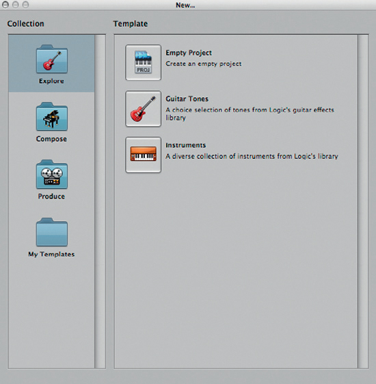
Figure 11.1 Logic’s template chooser can save time when starting a project using a template of your own making.
For example, if you do a lot of drum recording, with a guide bass, guitar, and vocals, it might be prudent to set up a template for this kind of recording, and perhaps, another template for working to picture. The benefits here are that all the tracks will be pre-labelled and, therefore, your audio files too when you hit record. This can be extended further to consider the mix, and if you find yourself using the same plug-ins and settings for your components of the drums, the template can have these preloaded as in the diagram opposite. It is perhaps sensible to put these into bypass mode (Alt + click) as this can save on DSP power. In this example, the drum outputs are all set to go to Bus 3, which in this case has been set up as a Drum Group or Stem.
Once you have created and saved your templates, they will appear in a new collection Folder within the Template Chooser called “My Templates.” These should provide you with personalized and honed platforms upon which to move forward fast with your projects.

Figure 11.2 Creating a template for a recording such as this can save time in the long run. Each strip can be automatically set up for sends and some with plug-ins as required. Ready to press ‘R’ and record!
Until Logic Pro 8, there were many individual windows to contend with. Each editor, mixer, list, and the Arrange window were all separate and individually controllable windows. That’s hard to believe now with the redesigned Arrange window with its “access all areas” philosophy. Logic’s solution to managing all those errant windows remains and is still very relevant in certain circumstances.
Working in Logic may require that a significant number of windows be opened on top of each other at a time. The most obvious examples would be an Arrange window and an editor open at the same time, or the Arrange window and Mixer together. Clearly, the current Arrange window can deal with most of these adequately. However, if you wish to open other windows, most applications would use the Command + “ ` ” (the one to the left of the “Z” key) shortcut to allow you to toggle through the open windows in the program one by one. However, given the need to access so many different combinations of the Arrange window, editors, mixers, etc., Logic adopts what it called Screensets to allow for quick and easy navigation.
Screensets are Logic’s ability to change what windows are viewed on the screen, or screens, at any time (a little like Mac OSX Spaces). On the title bar of Logic to the right-hand side of the Screenset menu, you will notice a number. This indicates the screenset you have chosen, and pressing one of the numbers on the numeric keypad can change this, or you can click on the Screenset menu for more options. Within this menu, you have the opportunity to rename your Screensets, duplicate them, and delete them. The key additional features available within this menu are “Lock” and “Revert to Saved.”
Lock allows you to set the way in which the screen looks so that it cannot be altered. A small bullet dot will appear to the left of the screenset number to indicate this. This can be really useful when you need to rely on your Screensets being just so! There will be times when the screenset changes you have made don’t work for you and you wish to revert to your original decisions without losing the audio recording and editing you have done. To do this, choose the Revert to Saved option from the Screensets menu.
The window combinations can be carefully thought out to maximize both your speed and screen space. For example, most users will keep Screenset 1 as the default Arrange window. However, whatever combination of windows you choose for each Screenset is entirely up to you. One example some users use is to follow the window keyboard commands as a guide; see Window from the main Logic menu. Doing this means that you can get to navigate to the Screenset, which focuses on the task you need. For example, Screenset 8 could be set up to be the Environment, or the Audio Mixer within the Environment window, which we’ll cover later in this chapter.
Screensets really come into their own with two monitors. As we’ve already mentioned, the new Arrange window is a very comprehensive space for achieving most things in Logic, although there will be particular times when you’ll want to see additional things, perhaps in larger windows or at the same time as something else. As such, Screensets could allow you, if you so desired, to manage the second monitor’s content, while leaving the Arrange window on the main monitor. Additionally, Screensets can also permit you to choose which editor or list is shown within the Arrange window. For example, one Screenset could show the Sample Editor, while another shows the Markers list.

Figure 11.3 The Screenset menu not only gives you options to edit and work with Screensets but also offers a clear indicator from the menu bar of which Screenset you’re currently working in.
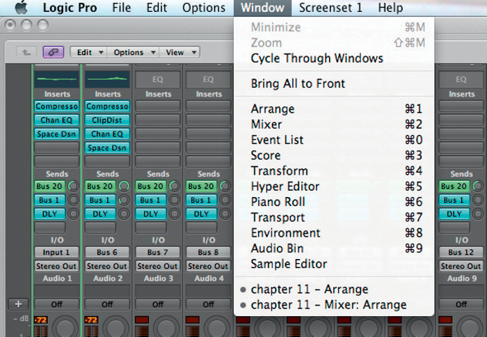
Figure 11.4 The Windows menu offers all the other views that can be spread across additional screens should you not wish to use the integral panes in the Arrange page.
Should you wish to see the Mixer and the Arrange window as in the picture opposite, then this is absolutely fine. Although there is another more integrated way of bringing up the Mixer using the Environment window, Logic allows for the Environment window to be loaded up as a floating window by pressing Alt as you go to Window > Environment. Before you do this, open a normal Environment window by going to Window > Environment, and change its view to “Mixer” using the arrow pointing down in the top left-hand side of the screen.
With this new floating Mixer window, shown below, it is possible to quickly navigate each track on the Arrange window and the Mixer will follow as though the link control was on, making it an extremely flexible and powerful way of working efficiently whether on a small, wide, or double-screen setup. To enable this, you need to ensure that the link icon is enabled in the main Environment window before making it float. This might seem as duplication to the Inspector’s expanded feature showing two Mixer elements, although you can, perhaps, be more dependent on the number of monitors you have. The alternative use for this is perhaps where you might disable the link and focus the floating Environment window (as a mixer) to the Master output. Now, directly from the Arrange window, we operate the focused track’s Mixer element in addition to the master bus.

Figures 11.5 and 11.6 Two windows can be made to sit side-by-side using Screensets as shown here, but it is also possible to create a floating Environment window, which can be linked to your actions on the Arrange area (below).

Figure 11.7 It is possible to import your project working preferences from another Logic File using the Import Settings feature.
Immediately, there are nine Screenset levels that can be accessed from the number keys on both the qwerty and numeric keypads. However, Logic allows you to access and make use of Screensets up to “99.” To key in these Screeensets, you need to press Ctrl and type the number of the corresponding Screenset. So for 34, simply press Ctrl + 3 and then Ctrl + 4, on the numbers on the qwerty keyboard.
At times you may receive a file you have been asked to mix, which will have different Screensets and perhaps different key command settings. It is important that your workflow is not jeopardized and that you can work both efficiently and productively with your preferences. To import project settings from another Logic File, go to File > Project Settings > Import Project Settings.
When you create multi-windowed Screensets, it is often a good idea to use one of the link modes to connect them all together when editing. As we have mentioned earlier in the book, Link allows you to click on another region and its contents to be displayed in the accompanying editor. This is highly beneficial and ensures that you can work really fast while keeping all the windows you need open. If this feature did not exist you’d need to close the window and perhaps double-click on the new region each time. Laborious!
Link has two discrete modes. The first is Same Link Level (pink icon), which means that whatever item you click on, whether that be a region, or the note, the linked windows will follow the same level. Confusing isn’t it? Well this can be useful if you have a number of editors open at any one time. A good way to see this working is by opening a separate Events List window (Cmd + 0) and, within the Arrange area, selecting a MIDI region. The Events List should show a list of the regions. However, if you press “P” to open up the Piano Roll Editor and then select on the MIDI notes, the Events List will change to the same level or class of data, in this case a MIDI note within all the notes in the region.
Content Link (Yellow Icon) differs in that you always see the content of the region. So in the example above, if we clicked on the region in the Arrange area, the Events List represented a list of the regions, but if in Content Link Mode we selected a MIDI note in the Piano Roll, then the MIDI note would be shown in the Events List. With Content Link, we can simply click on the MIDI region in the Arrange area to immediately see its contents in the Events List, therefore seeing the content level without having to select it separately in the Piano Roll.
These differences are ever so subtle, and frankly, it is one of those things that if the windows are not linking as you need them to, then simply Ctrl + click the link icon, change the mode, and see if that works the way you want it to. Nevertheless, the Link mode is a key feature of Logic as it does ensure that Screensets can operate fluidly without the need to shut an editor down to then double-click an alternative region to look at its notes!
Keyboard shortcuts are a useful way of improving the workflow with whatever software you are using from a word processor to an Internet browser. Logic, of course, is no different, and as you’d expect, there are so many of them covering a vast number of the features. Throughout this book, we give you the default key commands that relate to what we have covered. Most of these commands can be learnt by noting the writing to the right of the command in one of the menus, but the whole range can be viewed in their own dedicated Key Commands viewer (Logic Pro > Preferences > Key Commands… or Alt + K).
Searching for Key Commands is easy by using the Spotlight-like search bar on the top right of the pane. In here, simply type in the command you wish to find the key command for and the possible results will appear under one of the main headings in the command list. Under each of these 17 headings, are all the key commands available for use with Logic. Not all of these commands will have a shortcut associated with them as there are simply too many. But as with all things in Logic, they too can be optimized or altered to suit your working needs.

Figure 11.8 Key Commands are an important feature of any piece of software to increase productivity. Logic is no exception allowing you to carve out a key command for literally every feature.
Once you have selected the instruction you wish to create a key command for, select it and choose to either “Learn by Key Label” or “Learn by Key Position” followed by the key combination you wish to use. There are subtle differences between these buttons. Logic allows you to discern between using the numerical keypad and using the numbers on the main part of the keyboard. In this way, you could choose to assign two different commands to number 9, one would be on the main keyboard and the other on the numerical keypad. Therefore, learning by Key Label means that using the number 1 will call up the same key command whether it is on the numerical keypad or above the qwerty. However, the Key Position option will allow you to discern between the two differing positions, thus giving you further key command possibilities.
There will, perhaps, come a time when you will develop your own key commands and see your productivity suit the way in which you work. Your templates will already preload your key commands with your work if you saved them, but there may come a time when you have to work on an imported project such as a mix that someone else put together. In this instance, it is really important that you save a set of your personalized key commands.
There will be times when you may need to impose your special and personalized changes to another’s Logic session and will need to have your key commands ready. To do this, we need to export our key commands. To do this, simply press Alt + K from anywhere in Logic to bring up the Key Commands dialog. Within the Options menu is a command called Export Key Commands which will allow you to save your key commands. These can then easily be exported into another copy of Logic using the Import Key Commands instruction in the same menu. These key commands can also be saved to the clipboard for use as a reference, or for revision. It may even be worth doing this while you’re learning to use these commands.
If, however, you have learnt Logic’s default Key Command set and import another person’s project, you might be at a loss as to why so many of them did not work. In this case, it would be sensible to choose the option of “Initialize All Key Commands,” which will reset the commands to the factory standard.
Logic’s Environment window has an interesting reputation to the non-Logic using world. It has always held an almost mythical-like status, where many users have not wished to delve for the fear of it would mess their whole project up. Although the Environment is perhaps less used these days now that MIDI is not the main method of music communication between the application and the sound sources, it is still an important tool that allows the user to experiment and perhaps optimize his or her creative output. The Environment window is thus the route for information into and out of Logic and as such is something that is worth considering especially when working with MIDI. It is here that the virtual representation of your studio can be created, managed, and manipulated. In this section, we’ll give a quick overview of its core functions and its possibilities. Where you take it will be up to your creativity.
The Environment window itself could be simply looked upon as an area to organize your MIDI inputs and outputs and how they all connect together. However, there are some more angles, or layers, to it which we’ll explore a little here such as its Audio Mixer and Global Object layers. In essence, the Environment should show all the connections to and from Logic, both physical and internal.
The first layer in the list is the All Objects list, which shows you all the connections to Logic currently established. This includes MIDI, Audio, and internal connections such as ReWire. The next layer is Global Objects that allows you to specify any objects that are common to each layer. The Click and Ports layer refers to how the click track (metronome) is managed within the MIDI environment, and how the Ports connect to each MIDI input, whether that be physical through an interface (port) or the Caps Lock Keyboard. The MIDI Instr., or MIDI Instruments layer is to allow you to specify what each instrument is and to manage its operation from within Logic. The last is the Mixer layer, which allows you to create a customizable mixer layout to suit your way of working.

Figures 11.9 and 11.10 The Environment has a number of different layers, which can be selected using the menu at the top left-hand side of the window.
New layers can be created for different purposes by selecting “Create Layer” from the menu. It might be prudent to create perhaps an additional layer if you wished to use the Environment to control an external MIDI synthesizer using something we call a mixermap, or a controller. This map could allow a physical display of the controls of that MIDI synth within a new Environment layer. The benefit is here that any movements you make to the synth within Logic can be recalled and automated. What you choose to use on additional laters will depend on the way you work. Additional mixer layers might be an idea, one for the channels and another for auxiliary tracks, for example.

Figure 11.11 The Inspector is an important aspect of the Environment window and can be toggled in and out of view using the “I” key.
An additional dimension to the “layout” of your windows is the opportunity to make the Environment window a Frameless Floating window by selecting it from the View menu. If you press link on the Environment window before making it frameless, it will follow the regions you select as you move around the project. As the Environment window can be used for so many specialized and personalized facilities, it might be necessary to have it open on top of other windows. In this instance, create a Frameless window and place it in your screenset next to your Arrange window or however you see fit for your session management.
Each element within a layer is known as an object and hence we see the concept of the Environment. The objects and their connections make up how Logic operates. To see the types of object available, go to the New menu within the Environment window where you will be greeted by a long list. The list is grouped into four groups. The first is the objects themselves; the second is a collection of processors such as the Arpeggiator or Transformer. The third collection comprises simply two inputs: Physical Input and Sequencer Input. The Physical Input refers to the MIDI input from an external device, perhaps a master keyboard, whereas the Sequencer Input refers to what Logic “gets.” In other words, one could place a process such as the Arpeggiator between the Physical Input and the Sequencer Input. The last collection refers to Audio and external functionality such as new Internal connections, which include ReWire, and Audio objects such as auxiliary tracks.
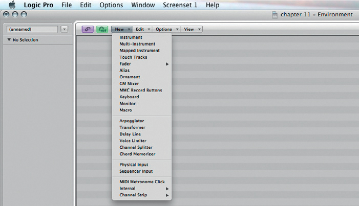
Figure 11.12 There are a considerable number of environment objects available to you to choose from to control Logic in a flexible manner.
Managing objects is simple as they can be moved, copied, and edited in a way similar to that of regions on the Arrange area. The Environment window also has an Inspector just as the Arrange window and can be toggled in and out of view using the “I” key. Selecting an object will reveal some editable features within the Inspector.
It is quite easy to create some unique layouts such as mixers which would benefit from being presented in a structured and uniform manner. When creating an environment, it is easy for the objects to not quite line up. As with many graphics applications, Logic’s Environment also includes a snap to grid-type facility called Snap Positions (in the Environment, View > Snap Positions). This will ensure that the objects you place can be easily managed and look smart!
Objects need to be connected to operate in many instances. Therefore, Logic provides “cables” to connect one object to another and can, therefore, be extremely flexible.
If you navigate to the Click & Ports layer, you’ll notice the Physical Inputs box has a number of white triangular arrows running down the right-hand side. These are connected to some writing that indicates which physical MIDI input they refer, such as Port 1, etc. Alternatively, at the top of this box is a SUM of all the physical inputs (which can be really useful if your master keyboard is away from your computer as you could employ the Caps Lock Keyboard or another smaller keyboard) and either signal will be passed into Logic.
It is likely that the SUM output of the Physical Input box has, by default, been connected to an Input Notes keyboard on screen, which allows you to click and preview notes as though you were playing a keyboard. This is usually automatically connected to what is labelled as the Input View, but is actually known as a Monitor Object. This shows you the MIDI information as you play the keyboard, which is usually a Note On message followed by a Note Off for each key pressed. MIDI information then travels through the cable connected to the Sequencer Input, which connects to your chosen track on the Arrange window.
As a default, this is great as it allows you to see how the Environment connects, and it is at this point that you perhaps might wish to experiment a little. For example, try creating an Arpeggiator and another Monitor Object. The idea here is to place the Arpeggiator after the original Input View Monitor to create a new musical arrangement. This could then be outputted to another Monitor Object to see what changes have been made to your input. With this arrangement of objects, anything played in on any physical inputs will be subjected to an Arpeggiator.
The Arpeggiator will run at the tempo of the project, and its response and range can be altered by selecting it in the Environment and visiting the Inspector to the left of the screen.
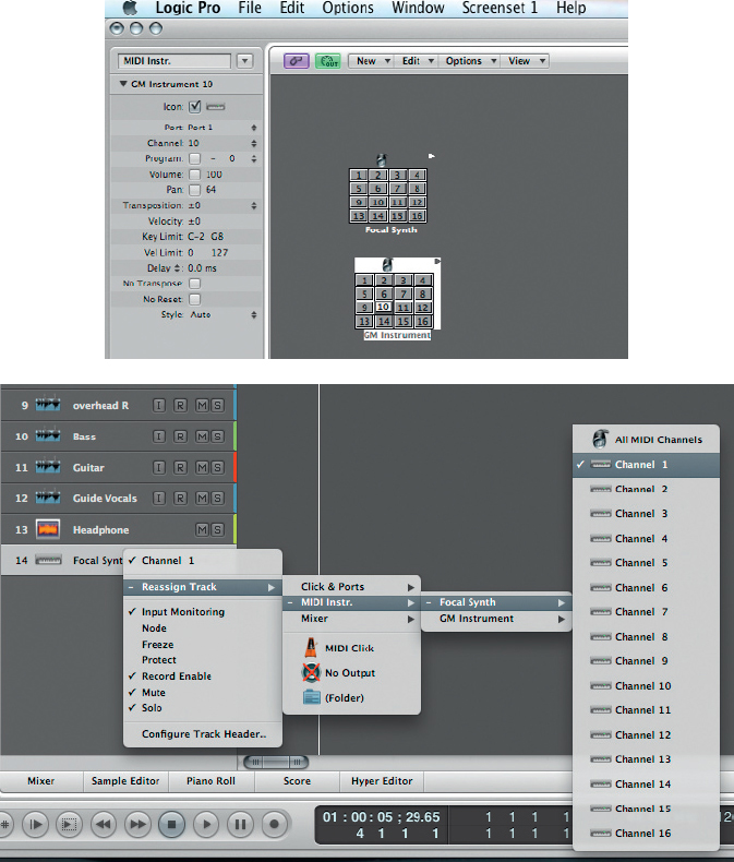
As Click & Ports generally refers to the input side of Logic, there is so much experimentation we can do here. There are obviously many more options: we could try working on the output of Logic, which can be quickly demonstrated by moving the mixer layer and adding in a new Arpeggiator into the environment. Connect this to a software instrument channel at the top of the fader. This new Arpeggiator object on the Mixer will now be available on the Arrange window. Create a new track and Ctrl + click the track header to open up the Reassign Track Object menu. From here, select the Mixer submenu and you should see the word Arpeggiator written in. This will now allow you to record and play only the source notes, which will then be arpeggiated each time the sequence is played.
It is quite possible that the cables on an environment may get so frenetic that you’ll not be in a position to see the objects! Within each layer is the option to view or hide the cables, thus allowing you to see what is going on. Simply go to the View menu and select Cables. This will hide them until the next time you need them. To make the workflow quicker, you can simply press Ctrl + C to toggle them in and out of view.
Another dimension is the ability to color your environment cables by clicking on the source, i.e., the device that is outputting to the cable, and pressing Alt + C or View > “Colors….” Change the color as necessary to enable quick access to the appropriate element of your environment. Remember these can simply get toggled out of view if it all becomes too much.
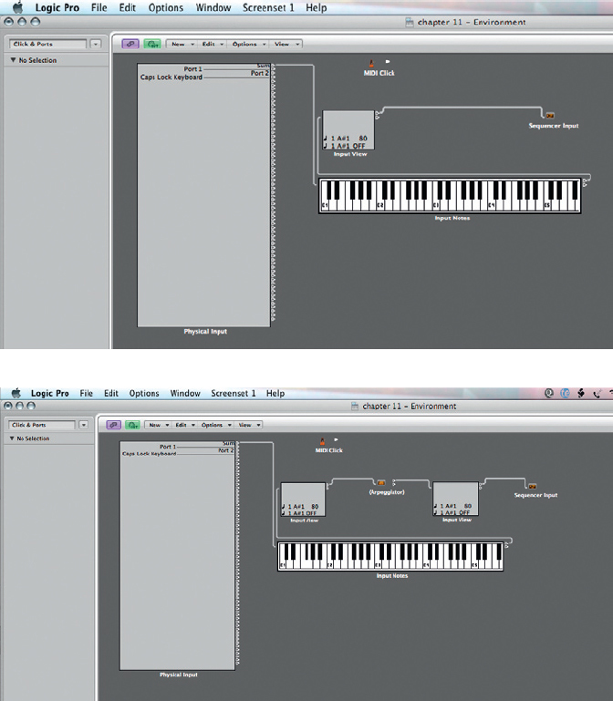
Figures 11.13 and 11.14 Using the Environment to create unique and interesting creative aspects to your work is easy. In the examples above, we have placed an Arpeggiator across any MIDI input to Logic.
Setting Up MIDI Instruments in the Environment
The MIDI Instruments Layer is an important one as it allows you to specify the MIDI environment and the synths and devices you have attached to your system. For example, if you bring in a new MIDI synth to your setup, you could simply just tell Logic there is a new instrument connected and this will allow you to select it from the track assignments, which is fine, but there is so much more that can be done.
Creating a new instrument within the MIDI Instruments layer will enable a new instrument to be located within the Reassign Track Object menu meaning that you can directly select the device and its channel from the Arrange window. To do this, we need to create a new Environment Object, and there are two main alternatives for MIDI instruments. The first is to create a new “Instrument” (New > Instrument). This means that this output will go to one MIDI channel from any port. There are some classic examples of MIDI instruments which are not multitimbral such as the Waldorf Pulse, which is a single MIDI-channelled monosynth.

Figure 11.15 It is easy to view, hide, or protect the Environment’s cables by going to View > Cables in the Environment.
For larger multitimbral synthesizers, we’ll need to create a “Multi-Instrument.” This can allow us to specify quite a lot about the device in question. As you select this, you’re confronted by a box with 16 small buttons. These will all be crossed off. This is essentially to save your time as not all multitimbral synthesizers are able to use all 16 MIDI channels. Therefore, you can specify which outputs you wish to use. Another reason for limiting the output of certain channels might be because you may wish to use a channel from the same physical output, if your MIDI outputs are limited, to send to a monosynth such as the pulse on channel 16.
After creating an instrument object, you will need to connect it to an output port. To do this, simply select the instrument in question and visit the Inspector to the left of the Environment window. Usually, directly under the Icon checkbox is a drop-down menu which lists all the available physical ports. Simply select the physical MIDI port you have connected the device to and you can use the instrument straight away from the Arrange window. This is known in Logic speak as a direct output assignment.
Once you have set the device using the multi-instrument object, you can double-click the object to reveal the Multi-Instrument Window. This immediately shows the instrument names for a General MIDI device (GM Device) that relate to a program change that can be sent by the sequencer. The idea is that you can relabel the instruments within Logic as they relate to their corresponding program change number. Once this has been done, you can choose the instrument name when selecting the Track Assignment in the Arrange window. Although this might seem like a long-winded exercise for all your esoteric synths, the operation would only need to be completed once. That level of recall from the Arrange window is an excellent feature and once done can speed up your workflow without leaving your mix position.
Figures 11.16 and 11.17 Creating a new Multi-Instrument in the MIDI Instruments layer will allow you to create a new stream of MIDI information intended for this new device.
The Mapped Instrument Object can be useful when you wish to convert one type of MIDI input data to another. For example, you may have drum kit loaded in an external device, which does not follow the General MIDI drum convention. In that instance, it would be useful to call up a Mapped Instrument Object which can be double-clicked to open a chart which allows one note to be mapped to another in real time.

Figures 11.18 and 11.19 The Multi-Instrument window allows you to label the instruments or patches to their corresponding program change. This can be then selected from the Program Change menu in the Inspector.
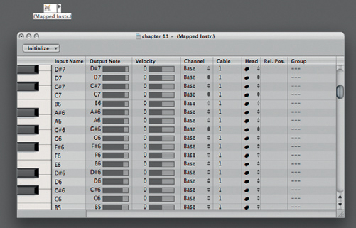
Figure 11.20 The Mapped Instrument Object converts one set of MIDI notes into another and is primarily useful for mapping drum kit sounds.
Walkthrough ![]()
Adding New MIDI Devices to the Environment
Step 1:

Figure 11.21
Adding a new MIDI instrument to the Environment will allow you to select it as a distinct item from the Reassign Track Objects menu. First, open up the Environment window, which is Cmd + 8 or Windows > Environment. With the Environment open, select the layer selection menu to the top left.
From this menu, select the MIDI Instruments layer abbreviated to “MIDI Instr.” This layer should see a GM Device, which is sometimes routed to the Quicktime Music Player.
Step 2:

Figure 11.22
To create a new instrument, choose the New menu. There are plenty of options available here, but namely we’re concerned with either a new Instrument or Multi-Instrument. An “Instrument” in this case is an instrument which only has one MIDI channel such as synthesiser. The Multi-Instrument alternative is for use with multitimbral MIDI devices such as a sound module or external sampler. It is important to establish which type your device is before connecting as it will make your selection easier from a track in the Arrange window. When this appears, you will need to route it out of a physical MIDI output. To do this, select the instrument object and visit the Inspector on the left to select the port it will output from.
Step 3:
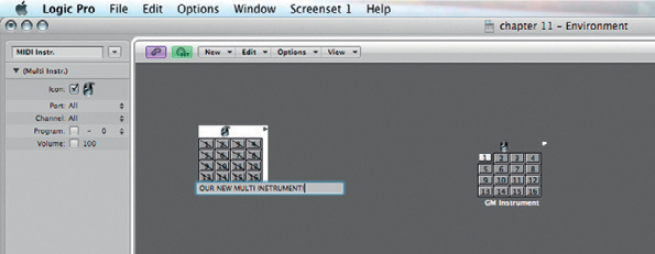
Figure 11.23
If you have chosen the Multi-Instrument option, a grid with 16 numbers will greet you, and they’ll all be crossed out. This is so that you can specify how multitimbral your device is. For example, some synths only can receive eight channels of MIDI, rather than the full quota of 16. In this instance, simply don’t deselect the last eight. This will ensure that Logic can only talk to the eight live channels. While you’re here, it is really handy if you label the instrument by either selecting the object and clicking on its name in the inspector or selecting the Text Tool from the Click Tools menu. Your device will be labelled and available from the track assignments in the Arrange window.
Live MIDI with the Environment
Earlier, we spoke of the Arpeggiator in terms of cabling and the creative effects it can have. The sheer number of objects possible within the Environment window allows for us to design some interesting and important facilities for working with MIDI. Whether that is an Arpeggiator or Multi-Instrument, the two together can make for some interesting outputs. This can of course be extended further if the fancy takes you. In the couple of examples below, we look at some aspects which can make Logic a useful tool when working live.
There are some interesting elements to the software which might be worth mentioning here. First is the Chord Memorizer Object whose job in life is to do a more clever version of what many lower end keyboards are renowned for: one note chords. The concept is that you can detail what the input note will be and what chord results from it. To create this simply visit the View menu and click on a Chord Memorizer Object. Next, double-click the object itself to reveal two keyboards which allow you to set which chord plays depending on which key would be pressed.
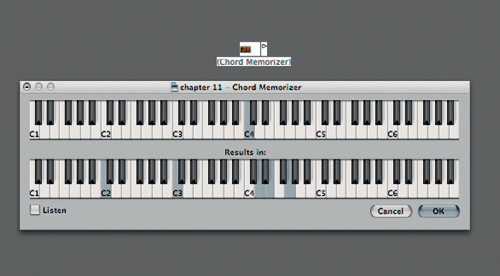
Figure 11.24 Chords can be memorized to be played using one key using the Chord Memorizer.
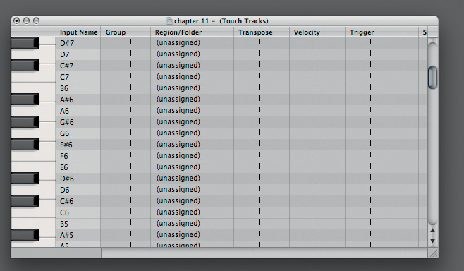
Figure 11.25 Touch Tracks enables Logic users to work with a range of MIDI regions mapped to various keys. Great for a live performance!
The Touch Tracks Object offers the Logic user a range of triggers to be enabled to play certain regions when pressed, like one of the functions of Ableton Live. This is a process which is limited to MIDI regions and Folder Track Regions. Select a Touch Tracks Object from the New menu and doubleclick it as it comes into view. Another table appears to allow you to assign a region or folder region to certain keys. This can be incredibly flexible when working live.
External Control with the Environment
One of the most flexible aspects of Logic is its ability to control external equipment which responds to MIDI. Whether to an external analog or a digital mixer that responds to MIDI messages or a synthesizer, Logic can control whatever functionality it allows using something termed a ‘Mixermap’. This can be extremely flexible to allow you to further control your equipment from the mix position. Any moves you make can be saved with the project as the MIDI can be saved as automation.
To enable this, simply create a new layer, which can be renamed as the device you’re planning on automating. Within this layer, create a series of objects which reflect the device and the controls you want to manipulate. Each object will have a different function to manage in the destination device. To alter this, we need to select each object and alter the MIDI message type it sends out. In the example on p. 394, we wish this fader to manage a volume; hence, this should be control change 7 on MIDI channel 1. This would need to be repeated for each channel and message for the Mixer.
There will, however, be instances where the MIDI data required will need to be somewhat more complex such as System Exclusive (Sys EX) which will be required for the mixermap. For these message types, it will be trickier to enable as this takes more knowledge of MIDI than the remit of this book, but is of course possible. If your external synthesizer follows General MIDI, then simply call up Logic’s own GM Mixer by creating a new layer and then visiting New > GM Mixer. This might be a good starting point for the creation of any new mixermaps.
When creating mixermap environments to control externally connected MIDI instruments, it is worth noting that these are best designed on the output side of the Environment. By “output side” we mean by cabling up the faders directly before introducing a physical output using an instrument object as can be seen in the diagram below.
There is a bit of a strange logic to this, but doing it this way, you immediately take control the device from the mixermap by connecting the fader objects through to the MIDI instrument. Logic immediately records any actions you make on the environment page should you wish to without the need to cable these object to another sequencer input.

Figure 11.26 To change the assignment of the fader, simply go to the Inspector and select the type of message and the corresponding number. In this case, we should send out a volume message.
Your MIDI device, which might be a mixer as in the environment example below, may also be able to transmit MIDI commands as you alter its physical controls. If so, these can be, in turn, fed-back into Logic and be reflected on the Environment’s mixermap, provided it is cabled correctly. This loop is necessary to ensure that both the physical and virtual controls are representative of each other. Fader objects on the Environment will only be controlled, though, if the physical device is routed back to the mixermap.
To do all this, simply create a new layer and name it “Mixermap” or something similar. Create an instrument (New > Instrument), which will act as your “Physical Output” directly to the MIDI-controlled device, in this example a mixer. It is worth ensuring that the icon checkbox is unchecked for this object as this does not prevent the icon from showing in the environment (we’ve changed it to a MIDI Plug here), but it will no longer show up in the Arrange area when selecting outputs.
Next select the faders and other object types that best describe how you wish to control the external device. Select each new object and specify its parameters, such as control change number 7 for volume and control change 10 for pan, if it were a GM Device. It is worth noting at this point that many MIDI devices use different message types than you’d expect, so it’s best to visit the corresponding manufacturer’s manual. Alternatively, put Logic into record and move the appropriate fader on the MIDI device. Once recorded, simply visit the Events List (Window > Events List or Cmd + 0) to ascertain what control change message it transmits. Later, we’ll show another easier way to do this in the Environment window.
In order for this to operate effectively, you need to cable up the faders and other objects to the newly created instrument we’ve called “Physical Output.” To the right-hand side of each object are some triangles that represent cable “sockets.” Simply click here and drag the mouse away to show some virtual cables, which can be dropped onto other objects to make a connection as in the example above.
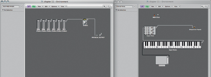
Figure 11.27 When making mixermaps, it is advisable to cable your fader objects directly to a physical MIDI output using an instrument object.

Figure 11.28 The icon checkbox does not prevent the icon being shown in the Environment itself, but refers to whether the selected instrument object appears in the outputs on the Arrange area.
These cables then need to be connected to the newly created “Physical Output” to transmit the changes you make on screen to the device. This should work provided the MIDI interface and MIDI device are operating properly.
However, we need to ensure that any movement on the physical controls on the MIDI device is reflected on your Environment Mixermap. To do this, we need to make a connection between the physical input to the Environment and the Mixermap layer. First, it is necessary to add a new monitor object to the newly created Mixer. This Monitor object will act as both a way of visualizing the MIDI information as we would in the Events List and as a method of connecting layers together. Connect the Monitor’s output to the first mixer object.
We then need to create a new instrument object on the Clicks & Ports environment page if you have not done so already for this MIDI device. In the example above, we’ve named it “MIDI-controlled Mixer.” If this were a synthesizer or sound module, then this will appear in the Arrange area track lists as usual.
To get the Mixermap Environment layer to respond, we need to cable this instrument object on the Clicks & Ports layer to the mixermap itself. Simply select a cable output from the instrument object on the Clicks & Ports layer, and with both layers open simply drag and drop the cables between layers to the Monitor Object. An easier way would be to Alt + click the output of the instrument object to which reveals a menu similar to that found on the track list on the Arrange area. This second method will only work, provided you have enabled the “Icon” check box which relates to the mixermap’s Monitor Object.
Provided all the objects are cabled correctly, your newly created mixermap should offer real flexibility to control devices directly from your Mix position. The open-ended nature of the Environment allows for many more possibilities to control devices within your studio.
When working within a large studio environment that brings together a fairly big analogue setup with many processors and a mixing console, there may be simply too many connections for you to remember which specific input relates to your prized Fairchild unit. Like with so many things within Logic, this can of course be labelled up on some physical inputs. To do this, select Options > Audio > I/O Labels… A new window opens showing all the physical inputs and auxiliaries within the system.

Figure 11.29 The Input/Output (I/O) Labels within Logic can be named to improve the workflow of your session. Naming the key inputs and outputs and auxiliaries makes things quicker.

Figure 11.30 The changes made in the Input/Output (I/O) Label dialog box makes all the difference with respect to quickly recognizing busses in the Mixer.
To change the names of connections, click either in the Long Name or in the Short Name boxes. The Long Name is your description and should be whittled down to a smaller amount of characters for the Short Name which will be used more frequently when accessing drop-down menus in the Mixer.
11.7 Nodes and Distributed Audio Processing
In Chapter 3, we briefly referred to distributed audio processing and the notion of Nodes. Here, we discuss how to set them up, get the best out of them, and what to do when you want to take the project away without the additional power of the node.

Figure 11.31 The nodes can be easily set up using the Nodes pane within the Audio Preferences.
Connecting Nodes to your Logic setup is very straightforward. This is achieved by visiting the Audio Preferences pane and selecting the Nodes tab. There is a small dialog box, which allows you to “Enable Logic Nodes.” With this option checked, Logic scans for computers connected to the host which have the Logic Node application running. It is not necessary to have Logic Pro installed, only the Logic Node program loaded on the slaved machine. Simply choose the computer you wish to act as the node and then, hey presto, this should allow for communication between Macs.
To make use of the node facility, you need to select which aspects of your production are handled externally by the node, or internally by the host computer. This selection is made possible through Track Node Checkboxes which can be revealed by visiting View > Configure Track Header.
The dialog box (below) appears offering you to customize the way in which you see the track’s header, which is the area to the left of the arrangement and immediately to the right of the Inspector. Within the Configure Track Header dialog box, the options to change the buttons on offer are selectable. Some useful buttons lurk here such as the Freeze Track icon and, in this instance, the Node button.

Figure 11.32 The Track Header Preferences allow for many changes including the Node Button asking whether or not a particular channel is to be managed by a Node.
A good way of keeping an eye on how your processing is distributed is to call up the Load Meters (CPU/HD) which now reside within the transport bar. To turn these on and off, you’ll need to Ctrl + Click the transport bar and then choose Customize Transport Bar… . Within here you’ll be able to select Load Meters (CPU/HD) under the Displays list.

Figure 11.33 Keeping an eye on the computer load can be turned on or off using the Transport Bar customizations.
Within the Load Meters, the CPU bar has perhaps more than one lane in it, which represents the number of processors within your Mac, whilst the Disk I/O shows the data through-put to your hard drive. As a node is added it expands to show the node’s CPU load, also allowing you to make a definite assessment of the project’s DSP distribution.
Through employing many of these features and thus tailoring the software’s behavior in the studio, Logic continues to be the trusted production tool for many professionals.