
Chapter 3. Distance
The two most common ways to measure distance are sound echoes and light reflection. To avoid annoying people with constant beeping and blinking, the sound frequency is usually so high that humans can’t hear it, and the light frequency is so low humans can’t see it. The high-frequency sound is ultrasonic, and the low-frequency light is infrared.
Even though infrared is invisible, we’ll show you how you can observe it with some common household items.
An ultrasonic sensor can provide exact distance readings. For example, it could tell you that the distance to an object is 36 cm.
To detect the proximity of humans and other living things, sensors can detect the heat they radiate. This lets you detect the presence of hot things in the measured area, but not their exact distance. There are many ways for heat to move: conduction, convection, and radiation. A passive infrared sensor measures radiated heat in the form of infrared light.
In contrast to passive infrared sensors, an active infrared distance sensor sends invisible light and tests whether it reflects back. It can tell if something is closer than a given distance. For example, an active infrared sensor could tell you that there is an object closer than 30 cm, but it wouldn’t know if it’s 5 cm or 29 cm away. As a rare exception, some sensors estimate distance from reflected infrared light.
A common use for active infrared is an automatic faucet and automatic hand dryer in a public toilet. Some automatic trashes open their lids when you go near them. Infrared light makes things more hygienic, as you don’t have to touch objects that many other people have touched.
Long-distance range finders can use a laser beam to measure distance. Most of them are based on factoring in the speed of light and the time it takes for a beam to be reflected. Because light is very fast, the circuit must be able to do very precise timing. This makes them quite expensive (prices start from $100 USD). They are far less commonly used for prototyping with Arduino or Raspberry Pi than sound and IR.
Experiment: Measure Distance with Ultrasonic Sound (PING)
Ping, 1, 2, 3… pong. An ultrasonic sensor sends a sound, and then measures the time for the echo to return. Because you know that sound moves at about 330 meters per second, your program can calculate the distance.
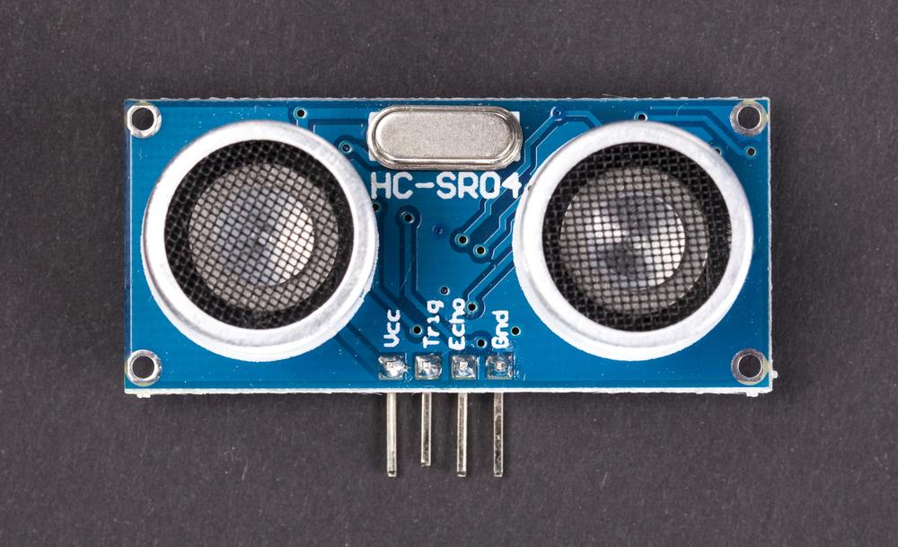
Nowadays, there are many cheap ultrasonic sensors inspired by the Ping sensor from Parallax (Figure 3-1). Later in this chapter, you’ll see some code for one of these cheap sensors, the HC-SR04 (HC-SR04 Ultrasonic Sensor). To better understand all the other ultrasonic sensors similar to Ping, it’s useful to be familiar with the original, so we’ll show you some code for that next. Also, many universities, hackerspaces, and makerspaces already have Ping sensors in their collections, so it’s a good one to know.
To understand how an ultrasonic sensor measures distance, see Echo Calculations Explained.
Ping is an older, popular sensor by Parallax. Compared with the alternatives, it’s a bit expensive, about $30 USD. If you need a lot of distance sensors, you might want something cheaper, but if you’re just buying one, Ping is a great choice. The similar HC-SR04 costs only a couple of dollars, and the only difference in configuration between the Ping and HC-SR04 is one pin. (HC-SR04 uses one pin to trigger sending a pulse and another to read the echo.) The sensors have almost identical code.

Ping Code and Connections for Arduino
Figure 3-2 shows the wiring diagram for the Ping sensor and Arduino. Build the circuit, and then compile and upload the code using the Arduino IDE.
You can download the example code from http://makesensors.botbook.com.
To see the readings, use the serial monitor (Arduino IDE→Tools→Serial Monitor). If you get gibberish instead of text, make sure that you specify the same speed (bit/s or “baud”) in both your code (Serial.begin) and the Arduino Serial Monitor.
Even though there is a lot of code in this example, it’s easy to reuse it so you can measure distance in your own projects. Just copy the supporting parts of the code (the distanceCm() function and global variables) and paste them into your own code. You can then measure distance with this line of code:
intd=distanceCm();
Because Ping works by listening to the echo of sound, its placement is quite important. If you always get the same reading (such as 2 cm), make sure that the wide beam of sound isn’t bouncing off of something, like the edge of your breadboard or a table. If you put Ping onto the edge of a breadboard, you’re not going to get reflections from it.
You can easily put Ping farther away from Arduino by using a servo extension cable, of the male-female type. Ping has just three pins, so it fits this type of cable perfectly.
Example 3-1 shows the complete code for reading a Ping ultrasonic distance sensor.

// distance_ping.ino - distance using ultrasonic ping sensor// (c) BotBook.com - Karvinen, Karvinen, ValtokariintpingPin=2;floatv=331.5+0.6*20;// m/s //voidsetup(){Serial.begin(115200);}floatdistanceCm(){// send sound pulsepinMode(pingPin,OUTPUT);//digitalWrite(pingPin,LOW);delayMicroseconds(3);//digitalWrite(pingPin,HIGH);delayMicroseconds(5);//digitalWrite(pingPin,LOW);// listen for echopinMode(pingPin,INPUT);floattUs=pulseIn(pingPin,HIGH);// microseconds //floatt=tUs/1000.0/1000.0/2;// s //floatd=t*v;// m //returnd*100;// cm}voidloop(){intd=distanceCm();//Serial.println(d,DEC);//delay(200);// ms //}

Calculate the speed of sound v for temperature 20 C (if your ambient temperature is significantly different, change 20 to the ambient temperature in C). The speed is about 340 meters per second or 1200 km/h.

Ping uses the same pin for input and output.

Wait for the pin to settle. 1 µs == 1 millionth of a second, or 1e-6 s == 0.000001 s

Send a very short beep. 5 µs, or 5e-6 s

Measure how long it takes for pingPin (D2) to go LOW, in microseconds.

Convert to SI (Système Internationale, metric) base units, seconds (see http://en.wikipedia.org/wiki/SI_base_unit). Notice we’re using a floating point divider (1000.0) instead of integer 1000 so that we get a floating point result. This one-way time is half of the round trip.

Distance is time multiplied by speed.

Measure distance and save it to a new variable, d. This is how you’d use it in your own code.

Print the value of d to the Serial Monitor.

Always have some delay in your loops. If you run your sketch without pausing, you’ll be taxing the Arduino CPU and wasting power (doing anything as fast as possible can take 100% of power on any single-core CPU).
Ping Code and Connections for Raspberry Pi
Build the circuit for Ping in Raspberry Pi as shown in Figure 3-3, and then run the code listed in Example 3-2.
Be careful when connecting anything to the GPIO header. A wrong connection can easily damage (at best) one pin or (at worst) your whole Raspberry Pi. You can avoid problems by disconnecting power when making or changing connections, and double-checking connections to the pins before powering up.

#distance_ping.py - print distance#(c) BotBook.com - Karvinen, Karvinen, Valtokariimporttime#importbotbook_gpioasgpio#defreadDistanceCm():sigPin=22v=(331.5+0.6*20)gpio.interruptMode(sigPin,"both")#gpio.mode(sigPin,"out")#gpio.write(sigPin,gpio.LOW)#time.sleep(0.5)#sgpio.write(sigPin,gpio.HIGH)#time.sleep(1/1000.0/1000.0)#gpio.mode(sigPin,"in")##Readhighpulsewidtht=gpio.pulseInHigh(sigPin)#s#d=t*vd=d/2#returnd*100#cmdefmain():d=readDistanceCm()#"Distance is %.2f cm"%d#time.sleep(0.5)if__name__=="__main__":main()
-
Importing the time library creates a namespace of the same name (time) that contains the library’s function, so this line lets you invoke
time.sleep(1)later in your code.-
To import your own libraries, they must be in the same directory. So make sure that botbook_gpio.py is in the same directory as distance_ping.py. You can find this directory in the sample code available from http://makesensors.botbook.com. (See GPIO Without Root for information on configuring your Raspberry Pi for GPIO access.)
-
The interrupt mode
bothmeans thatpulseInHigh()will measure a whole pulse from the signal’s rising edge (from 0 to 1) to the falling edge (from 1 back to 0).-
With the Ping sensor, we switch the same pin between “out” and “in” mode as needed. Other sensors, such as the HC-SR04, use separate pins for each function.
-
Turn off the pin and wait for the pin to settle. Half a second is a safe amount of time.
-
Start the pulse (rising edge). This is where the time-critical code starts.
-
Wait for a microsecond (1e-6 s), or one millionth of a second.
-
Set the pin to “in” mode. This has the side effect of turning off the pulse, creating the falling edge of the short pulse.
-
Read the pulse width in seconds.
gpio.pulseInHigh()measures the length of the whole pulse, from start (rising edge) to finish (falling edge). Raspbian runs a whole operating system, so timing is not as precise as with Arduino. Other programs running on the system can affect the timing.-
One-way distance is half of round trip.

This is the line you need for measuring distance in your own programs.

Print the distance to the terminal window that this program is running in. The “%.2f” is part of the format string. It marks a place for the variable d. “%f” is floating point (decimal), and “.2” means to show two decimal places. If you just used “print d,” you would get a very long decimal number.
HC-SR04 Ultrasonic Sensor
The HC-SR04 is just like the Ping but is available at a fraction of the cost. The code for this sensor is almost the same as Ping code, except the HC-SR04 uses separate pins for triggering the sound and listening for the echo. For detailed code explanations, see Ping Code and Connections for Arduino and Ping Code and Connections for Raspberry Pi; the explanations in this section will focus on the differences.
To understand how an ultrasonic sensor measures distance, jump ahead to Echo Calculations Explained.
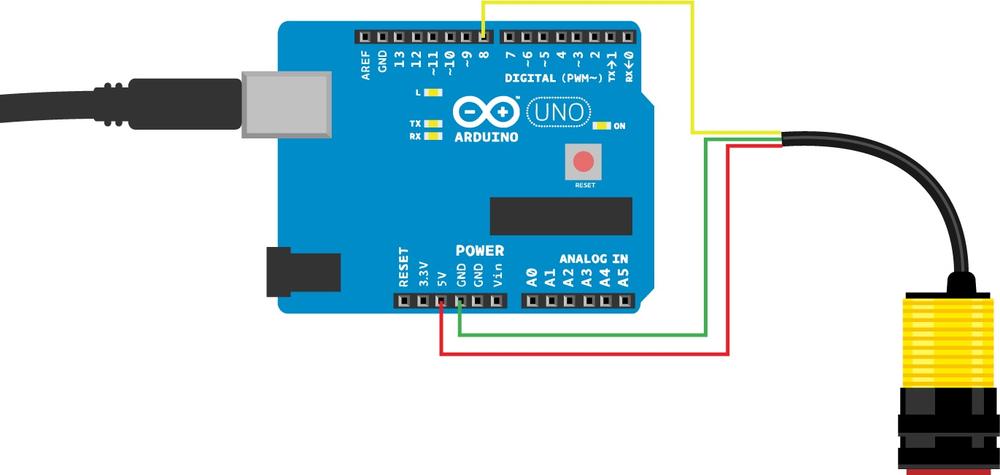
HC-SR04 Code and Connection for Arduino
Build the circuit as shown in Figure 3-5 and upload the code.

// hc_sr04.ino - print distance to serial// (c) BotBook.com - Karvinen, Karvinen, ValtokariinttrigPin=8;intechoPin=7;floatv=331.5+0.6*20;// m/svoidsetup(){Serial.begin(115200);pinMode(trigPin,OUTPUT);//pinMode(echoPin,INPUT);//}floatdistanceM(){// send sound pulsedigitalWrite(trigPin,LOW);delayMicroseconds(3);digitalWrite(trigPin,HIGH);delayMicroseconds(5);digitalWrite(trigPin,LOW);// listen for echofloattUs=pulseIn(echoPin,HIGH);// microsecondsfloatt=tUs/1000.0/1000.0/2;// sfloatd=t*v;// mreturnd*100;// cm}voidloop()//{intd=distanceM();Serial.println(d,DEC);delay(200);// ms}
-
With the Ping, we didn’t follow the normal practice of setting pin modes in the
setup()function because we had to keep changing them (the Ping has one pin used for both triggering a pulse and reading the reflection). HC-SR04 uses a pin labeled Trig for triggering the sound.-
The pin labeled Echo returns the time it took to read the reflected echo as a pulse length.
-
Other than the changes to the setup, using HC-SR04 in your main program looks a lot like the code you used for the Ping sensor.
HC-SR04 Code and Connections for Raspberry Pi
Build the circuit (Figure 3-6) and upload the code shown in Example 3-4. Take notice that in addition to jumper wires, you also need to add two 10 kOhm resistors. (To identify resistors, you can use the method described in The Third Stripe Rule.) The code is very similar to Ping.
# hc-sr04.py - print distance to object in cm# (c) BotBook.com - Karvinen, Karvinen, Valtokariimporttimeimportbotbook_gpioasgpiodefreadDistanceCm():triggerPin=22#echoPin=27v=(331.5+0.6*20)# m/sgpio.mode(triggerPin,"out")gpio.mode(echoPin,"in")gpio.interruptMode(echoPin,"both")gpio.write(triggerPin,gpio.LOW)time.sleep(0.5)gpio.write(triggerPin,gpio.HIGH)time.sleep(1/1000.0/1000.0)gpio.write(triggerPin,gpio.LOW)t=gpio.pulseInHigh(echoPin)# sd=t*vd=d/2returnd*100# cmdefmain():d=readDistanceCm()#"Distance is%.2fcm"%dtime.sleep(0.5)if__name__=="__main__":main()
-
The only difference from the Ping example is that HC-SR04 uses two pins (Trig and Echo).
-
You can read a result from the HC-SR04 just as you would with the Ping.

Why does the HC-SR04 need a resistor, but the Ping doesn’t? According to the HC-SR04 data sheet, its output is TTL level, which means +5 V. The data sheet for Ping promises compatibility with +3.3 V logic level. We verified these maximum values by measuring the output. The Raspberry Pi’s GPIO pins’ maximum voltage is +3.3 V, and sending +5 V to it would damage the pins or the Raspberry Pi.
Echo Calculations Explained
Thunderstorm nearby? You can estimate the distance to where lightning is striking by comparing the time between seeing lightning and hearing the thunder. Count the number of seconds after you see a lightning flash. Each second corresponds to 330 meters to the location of the strike (the actual number differs depending on the air temperature; we’ll get into this shortly).
To play with the math, 330 meters/second * 3 seconds = 990 meters, so the sound moves roughly one kilometer in 3 seconds (and roughly one mile in 5 seconds). We see light nearly instantly, but the sound takes more time to reach us.
An ultrasonic sensor typically measures distances from 3 cm to 6 m. If you buy a distance measuring tool (“ultrasonic tape measure”) from a hardware store, it can go farther, about 20 m (it uses a cone to project sound and a thermometer to calibrate the speed of sound for the current air temperature).
The time it takes for sound to travel 1 centimeter is very short, just 30 microseconds: 30 millionths of a second. How to come up with this number?
For a difficult problem, especially one involving very small or very large numbers, it’s helpful to model it as an analogous problem using familiar, everyday quantities. For example, if I drive for two hours (t) at the speed (v) of 50 km per hour, isn’t that an annoyingly slow trip? But with t and v, you can calculate the distance (d):
t = 2 h
v = 50 km/h
d = t*v = 2 h * 50 km / h =
    2*50 km * h/h = 100 km
That seemed easy. Now we know that two hours is equivalent to 100 km in this system. Let’s try the exact same formula with a very short time (3.33 milliseconds), much faster speed, and base units of meters and seconds. (A milli- prefix means one thousandth, so a millisecond is one thousandth of a second.)
t = 3.33 ms = 0.00333 s
v = 330 m/s
d = t*v = 0.00333 s * 330 m/s = 1.10 m
This is how you can measure distance in your program with the ultrasonic ping sensor: if it takes 3.33 milliseconds for the reflected sound to return to you, it’s traveled 1.1 m.
If you read code written by others, you might also see someone count a pace for sound. Instead of noting meters per second, many examples count the inverse, seconds per meter, expressed as milliseconds/meter here:
1/v = 1/(330 m/s) = 0.00303 s/m = 3.03 ms/m
It takes about 3 milliseconds for sound to move a meter.
Sound moves faster when it’s warm. Sound is the vibration of air, and the vibrations move better if air molecules are already vibrating with heat. If you live in a warm place, we envy you because you probably need less calibration. In the north of Finland, it might be +22 C inside and -40 C outside, resulting in over 60 C difference in temperature. A change this big will clearly affect measurements. Temperature (T) affects the speed of sound (r) according to the formula
v = (331.3+0.606*T) m/s
This formula gives the speed of sound in practice (343 m/s at 20 C). If you start getting fancy with it, you could be calibrating for many factors. If you climb to a mountain or live in a submarine, you must also take into account the change in air pressure. If you go from the Sahara to a laundry room, calibrate for air humidity, too. That said, common commercial ultrasonic distance measuring tools tend to calibrate for temperature only.
When you use these calculations in your code, just put them in the beginning of the code. Arduino or Raspberry Pi can calculate them in an instant, and calculations outside loop() are performed only once anyway. Be sure to comment these calculations, and you will thank yourself when you can understand your code a week later.
Environment Experiment: Invisible Objects
You can easily fool an ultrasonic sensor so that it thinks there is nothing in front of it. Attach the sensor to a helping hand tool (aka third hand tool) and point it at a solid, flat object. Upload the code and open the serial monitor as you did earlier in this chapter. Now you should get a normal distance reading.
Next, try putting a soft pillow or similar plush object between the sensor and the solid object (see Figure 3-7). Check the serial monitor again. Is the solid object still there?
Inclined planes are another Achilles’ heel of ultrasonic sound sensors. Remove the soft object and start tilting the solid flat object that is facing the sensor. Keep checking the serial monitor as you tilt the object to a steeper angle.
Why does this happen? Soft objects (like our Monty Python killer rabbit in Figure 3-7) absorb so much sound that there’s not enough echo. On the other hand, an inclined plane echoes the sound, but in the wrong direction (not back at the sensor). This is similar to how a stealth aircraft fools radar.

Experiment: Detect Obstacles With Infrared (IR Distance Sensor)
An infrared switch (Figure 3-8) is more reliable than an ultrasonic one, but less versatile. You can’t fool it as easily as you fooled ultrasound in the experiment you did earlier. But an infrared switch can tell you only if there is something present, not the distance to it. And because the sun is a great big source of infrared light, it’s strong enough to blind an infrared switch.


IR Switch Code and Connections for Arduino
Figure 3-10 shows how to connect Arduino to the infrared sensor. The sketch is shown in Example 3-5.
// adjustable_infrared_sensor_switch.ino - print detection to serial and light LED.// (c) BotBook.com - Karvinen, Karvinen, ValtokariconstintsensorPin=8;constintledPin=13;//Sensor valueintswitchState=0;voidsetup(){Serial.begin(115200);//pinMode(sensorPin,INPUT);pinMode(ledPin,OUTPUT);}voidloop(){switchState=digitalRead(sensorPin);//Serial.println(switchState);//if(switchState==0){digitalWrite(ledPin,HIGH);Serial.println("Object detected!");//}else{digitalWrite(ledPin,LOW);}delay(10);// ms //}
-
Open the Arduino Serial Monitor (Tools→Serial Monitor). You must set the same speed in your code and in the serial monitor. The fastest is 115,200 bit/second. If you have an unreliable (or very long) USB cable, change this to 9,600 bit/second.
-
An infrared sensor switch is just like a button. This is the line that reads the sensor.
-
Print the sensor pin state for debugging purposes.
-
A state of 0 means that an object is detected. We turn Arduino’s built-in LED on to indicate that an object was detected.
-
You should always have some, even tiny, delay in
loop(). This will prevent the sketch from using 100% of the Arduino’s CPU all the time.
IR Switch Code and Connections for Raspberry Pi
Figure 3-11 shows the wiring diagram for Raspberry Pi and the switch. The corresponding Python code is in Example 3-6.

# adjustable-infrared-sensor-switch.py - read infrared switch# (c) BotBook.com - Karvinen, Karvinen, Valtokariimporttimeimportbotbook_gpioasgpio#defmain():switchPin=27gpio.mode(switchPin,"in")#x=gpio.read(switchPin)#if(x==gpio.LOW):#"Something is inside detection range"else:"There is nothing inside detection range"time.sleep(0.1)if__name__=="__main__":main()
-
Import the botbook_gpio library. It must be in the same directory as this code, so make sure that botbook_gpio.py is in the same directory as adjustable-infrared-sensor-switch.py. You can find this directory in the sample code available from http://makesensors.botbook.com. (See GPIO Without Root for information on configuring your Raspberry Pi for GPIO access.)
-
Configure the pin that the switch is connected to; this puts it into input mode.
-
Read the state of the pin, and store it in the variable
x.-
If the pin is low, it means an object was detected in range.
Environment Experiment: How to See Infrared
As we mentioned earlier, infrared is outside the range of visible light. How could you see it if you were determined to do so? You could use night-vision goggles or, if you don’t have any of those handy, any cheap digital camera.
Try looking at an IR sensor through your smartphone’s camera. You should be able to see a violet glow on the IR emitter Figure 3-12. Dim the lights and close the curtains to make it even more visible. It’s not as cool as the night vision, but it is a quick and easy way to see that the emitter is working.
What if you want to try this with an expensive SLR camera? Be aware that some cameras have strong infrared filters that prevent unwanted wavelength from being part of your photos (it works with cheaper cameras because the infrared filters aren’t as good, so some infrared light manages to excite some of the sensors in your camera). If this is the case, you can go to a dark room and set your camera to a very slow shutter speed (possibly many seconds) and take a picture using a tripod. As the IR is the only light in the room, it will eventually appear in the picture.
If you happen to have night-vision goggles, they are perfect for observing how IR sensors work. Night-vision goggles amplify visible light, but they are especially greedy for infrared spectrum. The cheapest models actually rely solely on an IR beam they produce themselves. If the model you’re using has an IR emitter, be sure to turn it off (or tape it over) in order to see the weaker light from your IR distance sensor. The fun in using night-vision goggles is not just seeing that your sensor works, but also the reflections that IR light creates off of other objects (Figure 3-13).


Experiment: Follow Movement with Infrared (IR Compound Eye)
A compound eye has many infrared-sensitive transistors and LEDs. It can track movement within 20 centimeters. Even though it’s one sensor, each of the infrared (IR) light-sensitive transistors can be read separately. Ambient light correction is done by turning off the IR LEDs and comparing values.

The exact name of this sensor is “IR Compound Eye.” If you ever start inventing and selling sensors, please give them a unique code name in addition to such a general name. A unique code will make it much easier to search for the component.

If you want to improve readings from your compound eye, you must calibrate it. Wait for the night when there is no ambient IR light. Even closed window shades can pass IR light, so if you can’t wait for the night, go to your cellar or a windowless room. Build the circuit shown in Figure 3-16 so that you can measure values. Put paper in front of the sensor (about 20 cm away) and see how much the values differ for each pin. Values should be almost the same (+/- 100) with the paper. If one of the values is too high, you can block some of the IR light with opaque tape or shrink wrap. If the value is too low, block some IR light going to other sensors.
When you use this sensor, you’re measuring analog resistance. For the simplest example of reading analog resistance, see Experiment: Potentiometer (Variable Resistor, Pot).
Compound Eye Code and Connection for Arduino
Figure 3-16 shows the wiring diagram for Arduino and the compound eye. The Arduino sketch is shown in Example 3-7.

// compound_eye.ino - print distance and direction values to serial// (c) BotBook.com - Karvinen, Karvinen, ValtokariconstintirEnablePin=8;//constintirUpPin=0;constintirDownPin=2;constintirLeftPin=1;constintirRightPin=3;intdistance=0;//intirUpValue=0;intirDownValue=0;intirLeftValue=0;intirRightValue=0;voidsetup(){Serial.begin(115200);pinMode(irEnablePin,OUTPUT);}voidloop(){readSensor();//Serial.("Values:");//Serial.("irUpValue");Serial.(irUpValue);Serial.(",");Serial.("irDownValue");Serial.(irDownValue);Serial.(",");Serial.("irLeftValue");Serial.(irLeftValue);Serial.(",");Serial.("irRightValue");Serial.(irRightValue);Serial.(",");Serial.("distance");Serial.println(distance);delay(100);}voidreadSensor(){digitalWrite(irEnablePin,HIGH);//delay(5);// ms //irUpValue=analogRead(irUpPin);irDownValue=analogRead(irDownPin);irLeftValue=analogRead(irLeftPin);irRightValue=analogRead(irRightPin);intambientLight=0;//digitalWrite(irEnablePin,LOW);//delay(5);ambientLight=analogRead(irUpPin);//irUpValue=irUpValue-ambientLight;//ambientLight=analogRead(irDownPin);irDownValue=irDownValue-ambientLight;ambientLight=analogRead(irLeftPin);irLeftValue=irLeftValue-ambientLight;ambientLight=analogRead(irRightPin);irRightValue=irRightValue-ambientLight;distance=(irUpValue+irDownValue+irLeftValue+irRightValue)/4;//}
-
Pin numbers are declared constant (
const), so you won’t be able to change them elsewhere in your sketch (if you try to write code that reassigns them, even—perhaps especially—by accident, you’ll get an error when you try to verify or upload the sketch).-
Sensor values will be stored in global variables. Globals are available in all functions. In C and C++ (which Arduino is based on), it’s good practice to initialize variables at the same time you declare them (for example,
int foo = 0;).-
readSensor()will not return any values. Instead, it modifies some global variables. This way, it can modify multiple values when you run it.-
Print the results.
Serial.print()doesn’t add a newline (butSerial.println()will).-
Turn on the IR LED to illuminate the target for measurement.
-
Wait for the inputs to settle.
-
Start measuring ambient light (for example, the invisible IR light from the sun).
-
Turn off the IR LED. All light detected now is from ambient sources.
-
Use each of the IR-sensitive transistors to measure ambient light.
-
Remove the ambient light value from each of the sensors.
-
Calculate the average distance over all four IR-sensitive transistors.
Compound Eye Code and Connections for Raspberry Pi
The IR compound eye contains eight infrared-sensitive sensors, which are connected in pairs, so there is a total of four sensors you can read. Each IR sensor is read as an analog resistance sensor.
The Raspberry Pi requires an external ADC (analog-to-digital converter) to read the IR sensors. One MCP3002 chip can read two analog inputs. Because we need to read four sensors, we use two MCP3002 chips.
This circuit (shown in Figure 3-17) has many things in it, but the principle is simple: there are four analog resistance sensors, and you read them one by one. Build the circuit as shown, and then run the code shown in Example 3-8.

# compound_eye.py - read distance and direction.# (c) BotBook.com - Karvinen, Karvinen, Valtokariimporttimeimportbotbook_gpioasgpio#importbotbook_mcp3002asmcp#irUpValue=0#irDownValue=0irLeftValue=0irRightValue=0distance=0defreadCompoundEye():globalirUpValue,irDownValue,irLeftValue,irRightValue,distance#ledPin=25gpio.mode(ledPin,"out")#gpio.write(ledPin,gpio.HIGH)#Wait for sensors to get readytime.sleep(0.05)#irUpValue=mcp.readAnalog(0,0)#irDownValue=mcp.readAnalog(1,0)irLeftValue=mcp.readAnalog(0,1)irRightValue=mcp.readAnalog(1,1)ambientLight=0gpio.write(ledPin,gpio.LOW)#time.sleep(0.05)ambientLight=mcp.readAnalog(0,0)#irUpValue=irUpValue-ambientLight#ambientLight=mcp.readAnalog(1,0)#irDownValue=irDownValue-ambientLightambientLight=mcp.readAnalog(0,1)irLeftValue=irLeftValue-ambientLightambientLight=mcp.readAnalog(1,1)irRightValue=irRightValue-ambientLightdistance=(irUpValue+irDownValue+irLeftValue+irRightValue)/4#defmain():globalirUpValue,irDownValue,irLeftValue,irRightValue,distancewhileTrue:#readCompoundEye()#"Values:""Up:%f"%irUpValue"Down:%f"%irDownValue"Left:%f"%irLeftValue"Right:%f"%irRightValue"Distance:%f"%distancetime.sleep(0.5)# s #if__name__=="__main__":main()
-
Import
gpiofor turning digital pins (in this case, gpio25) on and off. The botbook_gpio.py file from the book’s sample code must be in the same directory as this program (compound_eye.py).-
Import the
mcp3002library for reading analog sensor values using MCP3002 analog-to-digital converter chip (ADC). You’ll use it for reading values of each of the IR light sensitive transistors. The botbook_mcp3002.py library file must be in the same directory as compound_eye.py. You must also install thespidevlibrary, which is imported by botbook_mcp3002.py. See the comments in the beginning of botbook_mcp3002/botbook_mcp3002.py or Installing SpiDev.-
Declare global variables.
-
To use global variables inside a function, they must be listed at the beginning of the function.
-
Turn on the gpio25 pin connected to IR LEDs. This will illuminate the target area for measurement.
-
Wait for the pins to settle.
-
Read each of the IR-sensitive transistor values. As Raspberry Pi has no built-in analog-digital conversion, we use the external MCP3002 chip.
-
To remove the effect of ambient light, we turn the IR LED off.
-
The value from each IR-sensitive transistor is read again.
-
The ambient light value is removed from the actual measurement (which was made with IR illumination).
-
The distance is the average of measurements from all four IR-sensitive transistors.

In embedded applications,
while(True)is a common method to keep performing the same action forever. Most embedded devices are supposed to keep doing their thing, and are not expected to exit the program and stop functioning after a while. To kill a program running in awhile(True)loop, press Control-C in the same terminal session you started it from.
The
readSensor()function doesn’t need to return any values, as it modifies global variables. In Python, you could alternatively return multiple values, as ina,b,c=foo().
When running a loop, a small delay ensures that this trivial loop doesn’t take 100% of the CPU time.
The compound eye has quite a few connections by itself. Combined with the ADCs, this means a lot of jumper wires.
Installing SpiDev
The MCP3002 analog-to-digital converter uses the SPI protocol. SPI is quite a complicated protocol, but you can install the SpiDev library to handle the details.
The SpiDev library is required by all code that uses import spidev. This includes the potentiometer code for Raspberry Pi, and every analog resistance sensor used in this book, because SpiDev is imported by botbook_mcp3002.
On your Raspberry Pi, open a terminal. First, install prerequisites:
$ sudo apt-get update
$ sudo apt-get -y install git python-dev
Download the latest version of SpiDev from its version control site:
$ git clone https://github.com/doceme/py-spidev.git
$ cd py-spidev/
And install it to your system:
$ sudo python setup.py install
Next, you need to enable the SPI module on the Raspberry Pi. First, make sure it is not disabled. Edit the /etc/modprobe.d/raspi-blacklist.conf with the command sudoedit /etc/modprobe.d/raspi-blacklist.conf and delete this line:
blacklist spi-bcm2708
Save the file: press Control-X, type y, and then press Enter or Return.
To allow access to SPI without root, copy the udev file from Example 3-9 (or from the example code in the botbook_mcp3002 directory) into place:
$ sudo cp 99-spi.rules /etc/udev/rules.d/99-spi.rules
# /etc/udev/rules.d/99-spi.rules - SPI without root on Raspberry Pi# Copyright 2013 http://BotBook.comSUBSYSTEM=="spidev",MODE="0666"
Reboot your Raspberry Pi, open LXTerminal, and confirm that you can see the SPI devices and that the ownership is correct:
$ ls -l /dev/spi*The listing should show two files, and they should list permissions of crw-rw-rwT. If not, go over the preceding steps again.
Now you can use MCP3002 chip and other SPI devices with Raspberry Pi.
Alternative Circuits for Raspberry Pi
The Raspberry Pi circuit for IR compound eye is quite complicated. Even though it’s not hard to understand, it has a lot of wires to connect. To build a simpler system, you could either use a another ADC or an Arduino (see Pi + Arduino).
To get by with just one ADC chip, you could use MCP3008 ADC, which has eight inputs. That would require modifying the botbook_mcp3002 library, though. You could also look into using Adafruit’s MCP3008 code (see https://github.com/adafruit/Adafruit-Raspberry-Pi-Python-Code).
Test Project: Posture Alarm (Arduino)
Every geek knows this problem: the more intensely you work, the closer your head moves to the computer screen. This is not quite how Mother Nature intended our posture. By combining an IR distance sensor and a piezo beeper, you can easily build a gadget that will warn you when you are too close to the screen (Figure 3-18).
What You’ll Learn
In the Posture Alarm project, you’ll learn how to:
- Combine input, processing, and output.
- Play tones with a piezo beeper.
- Enclose your project.
Piezo Beeper
A piezoelectric crystal changes shape when you apply voltage to it. By using alternating current (AC) or a simple on-off square wave, you can make the piezo crystal vibrate. This makes the air vibrate, and air vibration is sound. In this case, an annoying sound.

The most common piezo element beeps when you send it a square wave (Figure 3-19). A square wave varies between HIGH (5 V for Arduino) and LOW (0 V).
You can easily create a square wave by repeatedly turning a data pin on and off with digitalWrite. Alternatively, you could use the built-in tone() function that uses a more advanced and complicated implementation to produce the same wave.
The piezoelectric phenomena also works the other way: you can generate electricity by squeezing a piezoelectric crystal. Electric lighters often use the piezoelectric effect to create a spark.

// piezo_beep.ino - beep on a given frequency with a piezo speaker// (c) BotBook.com - Karvinen, Karvinen, ValtokariintspeakerPin=10;voidwave(intpin,floatfrequency,intduration)//{floatperiod=1/frequency*1000*1000;// microseconds (us) //longintstartTime=millis();//while(millis()-startTime<duration){//digitalWrite(pin,HIGH);//delayMicroseconds(period/2);digitalWrite(pin,LOW);delayMicroseconds(period/2);}}voidsetup(){pinMode(speakerPin,OUTPUT);}voidloop(){wave(speakerPin,440,500);//delay(500);}
-
To use the
wavefunction in your own projects, you just need to specify pin, note frequency, and duration in milliseconds. The contents of the function are implementation details: educational, but not required for using the function yourself.-
Calculate the period T: how long does one wave (one HIGH + one LOW) take? It is the inverse of frequency f:
T = 1/f. For example, if you have 2 waves in one second (2 hertz, which is2 * 1/s), one wave will take half a second (1 / 2 Hz, or1/(2 * 1/s), which works out to1/2 s). Note that hertz (number of cycles per second) is abbreviated Hz.-
This is a common pattern used in code to perform something for set time: first, save the starting time into a variable (
millisgives the number of milliseconds since the Arduino powered up)…-
…and wait until it’s been more than the specified duration since the starting time.
-
Create one whole wave. First create the high part, then the low part.
-
This call is all you need for creating a beep in your own main program.
Alarm, Alarm!
It’s time to advance from a beep to a whole new world of notes: the alarm.
// piezo_alarmtone.ino - use piezospeaker to sound alarm sound// (c) BotBook.com - Karvinen, Karvinen, ValtokariintspeakerPin=10;voidwave(intpin,floatfrequency,intduration)//{floatperiod=1/frequency*1000*1000;// microseconds (us)longintstartTime=millis();while(millis()-startTime<duration){digitalWrite(pin,HIGH);delayMicroseconds(period/2);digitalWrite(pin,LOW);delayMicroseconds(period/2);}}voidsetup(){pinMode(speakerPin,OUTPUT);}voidloop(){wave(speakerPin,440,40);//delay(25);wave(speakerPin,300,20);wave(speakerPin,540,40);delay(25);wave(speakerPin,440,20);wave(speakerPin,640,40);delay(25);wave(speakerPin,540,20);}
-
Use the exact same
wave()function you used to generate a simple beep.-
Play a note, wait for a very short time, play another… repeat forever.
Combining Piezo and IR Sensor
Build the posture alarm circuit (Figure 3-21). Upload the code and prepare for a life with better posture—or endless alarm.

// posture_alarm.ino - sound an alarm when IR switch detects bad posture// (c) BotBook.com - Karvinen, Karvinen, ValtokariintspeakerPin=10;constintsensorPin=2;intswitchState=0;voidwave(intpin,floatfrequency,intduration)//{floatperiod=1/frequency*1000*1000;// microseconds (us)longintstartTime=millis();while(millis()-startTime<duration){digitalWrite(pin,HIGH);delayMicroseconds(period/2);digitalWrite(pin,LOW);delayMicroseconds(period/2);}}voidalarm()//{wave(speakerPin,440,40);delay(25);wave(speakerPin,300,20);wave(speakerPin,540,40);delay(25);wave(speakerPin,440,20);wave(speakerPin,640,40);delay(25);wave(speakerPin,540,20);}voidsetup(){pinMode(speakerPin,OUTPUT);Serial.begin(115200);pinMode(sensorPin,INPUT);}voidloop(){switchState=digitalRead(sensorPin);Serial.println(switchState,BIN);if(switchState==0){//alarm();//}delay(10);}
-
Use the same
wave()function you’ve used before for creating beep and alarm.-
Use the same
alarm() you used earlier.-
Use the
digitalRead()function to get a value from the infrared distance switch, like you did before.-
If something is detected in the monitor’s area, play the alarm. In practice, if you put your head too close to the monitor, the alarm will sound.
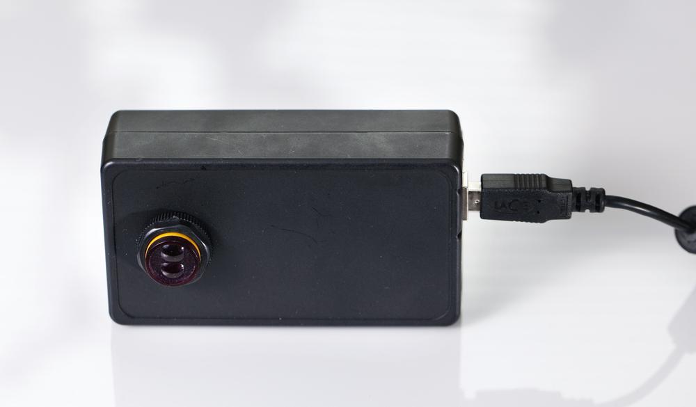
Putting Everything in a Neat Package
Prototypes are more impressive and robust when you put them inside an enclosure. We used a box for Arduino made by SmartProjects, because it happened to be an exact fit for this project. First we sprayed the whole thing black and made a hole for the infrared sensor with a 19 mm drill bit (see Figure 3-22).

We removed the little hatch from the back of the chassis to make the sensor fit inside better and to be able to adjust the distance screw later (see Figure 3-23).
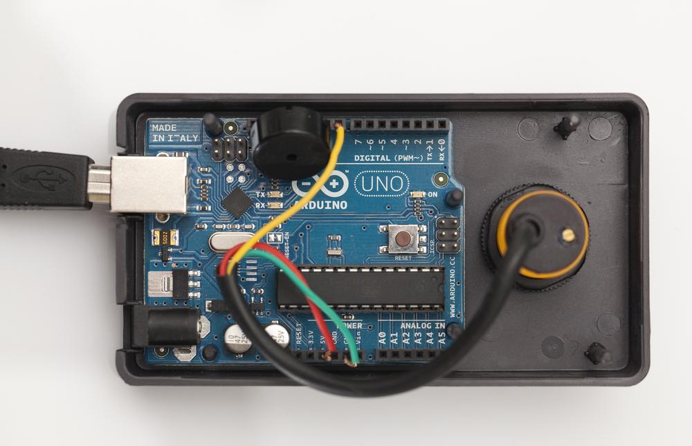
We attached the sensor in place with the plastic nuts that are part of it. You can slide the Arduino through the posts in the chassis, and it will stay put nicely, as shown in Figure 3-24.

Close the enclosure by pushing the top and bottom half together, and you’re ready to start protecting your posture (see Figure 3-18). This box has a ready-made hole for the USB cable, so now you actually have a neat-looking USB gadget to decorate your workspace.
You have now learned to measure distance using multiple methods. Your projects can know if something is near or how far it is to objects nearby. With more than one sensor, you can create more sophisticated behaviors. For example, combine two IR sensors with a servo motor and make it turn toward the direction of the nearest detected object. This way you would have a simple hand follower. Two IR receivers in a rover robot would enable it to follow flame. How will you use distance sensors in your projects?