
Chapter 14
A Pantograph
Do you want a device that makes a copy of a simple drawing, and enlarges it at the same time, while using no electricity at all? A gadget that consists of just a few pieces of wood, some screws and bolts, a pointer, and a pen?
That device is a pantograph, which will demonstrate some important concepts: rotating linkages, and nuts and bolts that connect them.
Nuts and Bolts for This Project
Check the Nuts and Bolts Fact Sheet on page 180 if you need basic information.
For this project, you can use ¼" size bolts that are 1" long with 20 threads per inch. You may see them listed in catalogs as ¼-20. The nuts must also be ¼-20, to match the bolts. You only need two nuts and two bolts, and can probably find small quantities in little plastic bags on hooks in your local hardware store.
You will also need washers. A basic washer is just a stamped circle of metal with a hole in the middle. Its purpose is to spread the force exerted by a nut or the head of a bolt, and also to reduce wear if the nut or the bolt rotates against a soft surface—such as a piece of wood.
I’d like you to buy fender washers such as the one shown in Figure 14-1. This type of washer is wider than a standard washer. The ones I am suggesting are described as ¼" size (to fit the bolt) and 1" in diameter. If you can only find ¾" diameter, they’ll do.

Figure 14-1. Fender washer, 1" diameter, for ¼" bolts.
If you are willing to take a little extra trouble, some refinements are possible.
Instead of generic nuts, you can buy locknuts with nylon inserts. The insert grips the thread of the bolt, and stops the nut from working loose.
Instead of generic 1" bolts, you can buy 1½" partially threaded bolts. These resemble wood screws because they have a smooth shank below the head, and the thread doesn’t start until halfway down. An example is shown in Figure 14-2. The ones you should buy must have 20 threads per inch, to match the nuts.

Figure 14-2. A partially threaded bolt (length 1½", size ¼").
I prefer this type of bolt for this project because each bolt will be inserted through two pieces of wood that rotate around it. If the bolt is threaded all the way up, the thread will tend to eat away at the wood, and the joint will become loose. A smooth shank at the top of the bolt inflicts much less wear—just like the smooth shank of a wood screw. The principle is illustrated in Figure 14-3.

Figure 14-3. When a softer material such as wood rotates around a bolt, a smooth shank reduces wear.
Partially threaded bolts are also known as partially threaded hex screws, when they have hexagon-shaped heads. For this project, ideally they should be ¼" diameter and 1" long, with half of the body threaded and the other half smooth. Unfortunately I have never seen this specification, so I used bolts 1½" long with about ¾" of the body threaded, as in Figure 14-2. They are longer than necessary, but they’ll do.
If you don’t want the hassle of finding this type of bolt, and you don’t want to pay for a substantial minimum quantity, use generic 1" bolts that are conventionally threaded.
Head Profiles
Larger bolts mostly have hexagonal heads. Smaller bolts may have other styles of heads, similar to the range available for wood screws and sheet-metal screws.
A selection of screws is shown in Figure 10-33 on page 123, while a selection of bolts appears here in Figure 14-4. They range from one 1" long with a ½" diameter thread, at far left, to a #3 size bolt ¼" long, at far right. From left to right, the first two have hex heads, followed by flat head with straight slot, round head with straight slot, pan head with Phillips slot, flat head with Phillips slot, and pan head with Phillips slot. The plated steel bolts have a slightly blue tint, while the two pan-headed bolts look slightly brown, which is characteristic of stainless steel.

Figure 14-4. A variety of bolts.
For this project, the two bolts and the screws that are #10 size, 1¼" long must not have flat heads, because I don’t want them to be recessed into the wood. A countersink removes some wood, and I want as much wood as possible to be in contact with the shanks of the fasteners.
For the wood screws, you will be looking for either pan heads or round heads. Round heads seem to be more common than pan heads in wood screws, and often have straight screwdriver slots instead of a Phillips head. Any type with an underside of the head that is not beveled will be okay.
Tools for Nuts and Bolts
I’m going to assume that you may not have any wrenches for working with nuts and bolts, so here’s a quick primer.
A nut has an internal thread that matches the thread on the bolt, so that if you hold the bolt stationary while you turn the nut, the nut moves up the thread toward the head of the bolt, and can exert a powerful gripping force on anything in between.
To make this happen, you need a tool that is stronger than your fingers. A wrench is the obvious choice, and a small adjustable wrench is the cheapest way to go. It does have disadvantages: it only grips two of the six sides of a nut, and tends to slip off, but it should be good enough for the projects in this book, and you can buy one online for less than the price of a hamburger (without fries). An example is shown in Figure 14-5. Other alternatives for gripping and turning hexagon-shaped nuts and bolt heads are described in the Nuts and Bolts Fact Sheet on page 180.

Figure 14-5. A low-cost adjustable wrench.
If you want to turn a nut while preventing the bolt from turning (or vice-versa), you need a way to grip both of them at the same time. This is not a problem if your bolt has a Phillips head: you immobilize it with a Phillips screwdriver, while you use your wrench on the nut. However, if you have a bolt with a hex head, you now have two hexagon-shaped things to grip, and you only have one wrench.
The easy answer is to use pliers on the part that you want to prevent from turning. This is not the right thing to do, because pliers tend to slip, and when they slip, they chew up the metal. But if you don’t expect to do a lot of work with nuts and bolts in the future, pliers will be okay for the projects in this book.
Choosing the Wood
Your pantograph will be fabricated from four strips of wood, each of which is 16½" long, ¼" thick, and about 1½" wide. You could use plywood, but for this project, I prefer something with harder edges.
At my local big-box store I found so-called “hobby board” made of ¼" poplar. This is not the hardest wood, but hard enough. The strips are 3½" wide, but slicing them down the middle to make narrower strips does not require much work, because the wood is so thin. Also, when you’re cutting parallel with the grain, the saw doesn’t create significant splinters, and you don’t need sacrificial wood. See Figure 14-6.
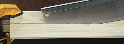
Figure 14-6. When slicing a strip of poplar parallel with the grain, no sacrificial wood is needed.
You can search online for narrower strips that don’t require any cutting, but for me, the hobby board was a quick and simple solution. Here’s the procedure:
- ■ Buy at least 36" of ¼" x 3½".
- ■ Cut two lengths out of it, each measuring 16½" long and 3½" wide.
- ■ Slice each section into two pieces, each measuring 16½" long and slightly more than 1½" wide. (Making a long cut like this, with the grain, is known as ripping the wood.)
- ■ You end up with four strips. Use your pencil to number the strips 1, 2, 3, and 4.
The length of each strip is important, but the exact width is not.
Identifying the Parts
Figure 14-7 gives you an idea of what a pantograph looks like. In this diagram, someone is using it to trace a simple drawing and make a copy that is 1.5 times as big. Note that the arms of the pantograph have holes in them (which penetrate all the way through). The holes allow the arms to pivot around screws and bolts. Extra holes allow configurations that will magnify the original drawing by a factor of 1.5, 2, 3, or 5.

Figure 14-7. A pantograph being used to make a copy 1.5 times as big as the original.
Drilling the Holes
Figure 14-8 shows the sizes and locations of the holes that you need to drill. The locations are identical in all four of the pieces. Even though you’re using hardwood, you should take some trouble to drill into sacrificial wood below it, as I have described in previous projects. Rough-edged, splintery holes will interfere with the assembly of this project.

Figure 14-8. Locations of holes to be drilled in each of four pieces. Don’t forget to label the ends A and B.
I suggest using an awl to mark each location, then drill all of the locations with a 1/8" bit, then all of them with a 3/16" bit. Finally enlarge the four holes in the middle to ¼", while the holes at the ends remain 3/16".
Using a countersink is not a good idea, because I want to maintain the full thickness of the wood around each hole.
Perhaps you are thinking that since the holes are in the same positions in each strip, you could stack the strips, clamp them, and drill through all of them at once. Yes, you could do that, but if your drill isn’t precisely vertical, the spacing of the holes in the lower pieces of wood will be inaccurate. I think it’s best to drill one strip at a time.
- ■ After you drill the holes in each strip, label the ends A and B as in the diagram.
Each end labeled A has a nearest hole 3" away. Each end labeled B has a nearest hole 5" away.
Throughout the text, I’m going to refer to the strips of wood as Arm 1, Arm 2, Arm 3, and Arm 4, as shown in Figure 14-7. Refer back to that figure while you are building this project, because identifying the arms and getting them the right way around is essential. Overlapping them correctly will also be important.
In Figure 14-7, the arms are shown with rounded ends. You’ll find in the photographs throughout this project that I rounded the ends of the arms in my pantograph. Whether you bother to do this is up to you. It makes no functional difference.
Fabricating a Pencil Gripper
The output from the pantograph is created with a pen or pencil that has to be gripped by some kind of gadget at the end of Arm 3. I’ll deal with this first.
I suggest you begin by paging ahead to Figure 14-23, so that you can see what the pencil gripper looks like when it is complete. Then the steps along the way will be a little less mysterious.
Select Arm 3. You’re going to operate on the B end, so make sure it’s the right way around. Figure 14-9 shows the plan for drilling this arm. The gray lines are pencil lines.

Figure 14-9. The plan for the B end of Arm 3.
Figure 14-10 shows the actual work piece. First draw lines across the arm using a speed square, then use your awl to make two prick marks, each 3/8" from the center line.

Figure 14-10. Arm 3 with awl marks 3/8" either side of the center line.
The next step is to drill a 1/8" screw hole on each prick mark, all the way through, and use a countersink to bevel these holes, because they are not going to rotate around bolts or screws. See Figure 14-11.

Figure 14-11. Arm 3 with beveled 1/8" holes.
Enlarge the end hole in Arm 3 from 3/16" to 3/8" diameter. If you are going to be using a pen that is fatter than 3/8", you need to enlarge this hole even more. Since 3/8" is your largest drill bit, you can use a ½" countersink (pushing it all the way through the wood) if necessary. See Figure 14-12.

Figure 14-12. The hole at the end of the arm has been enlarged to 3/8".
The last step in this sequence is to saw along the line that crosses the hole, as in Figure 14-13.

Figure 14-13. The end of Arm 3 has been removed.
Now set aside Arm 3 and cut two pieces of ¾" x ¾" square dowel, each 4" long. Use your speed square to draw a line marking the midpoint of each one, as shown in Figure 14-14.

Figure 14-14. Mark the midpoints of two dowels.
Clamp the two dowels and drill a 5/32" hole where they touch each other, as in Figure 14-15. If they are clamped firmly, the drill shouldn’t push them apart. Enlarge this hole to 7/32" and finally ¼". This is going to be your pencil gripper.

Figure 14-15. Making a hole where the dowels touch each other.
After you release the dowels, they should look like Figure 14-16.

Figure 14-16. This will become your pencil gripper in the pantograph.
Clamp one of the dowels under the end of Arm 3 as in Figure 14-17, so that the edges are aligned, the centers are aligned, and the semicircular notches are aligned. In the screw hole that is exposed, drill a 3/32" pilot hole down about ½" deep in the dowel.

Figure 14-17. One of the dowels is clamped under the end of Arm 3. Drill a 3/32" pilot hole through the screw hole, ½" into the dowel.
Insert a #6 size, 5/8" screw as in Figure 14-18.

Figure 14-18. A screw has been inserted in the pilot hole.
Now swap the clamps around to expose the other hole, drill a pilot hole there, and insert another #6 size, 5/8" screw.
When you’ve done this, go back to your other piece of dowel. In Figure 14-19, notice that the notch that you drilled in it is facing downward. Make two marks with your awl, each 5/8" from the center line. Then drill screw holes at these locations, all the way through the dowel, with a 3/16" bit.

Figure 14-19. In the second dowel, each awl mark is 5/8" from the center line. The notch in the dowel points downward. Drill holes with a 3/16" bit.
It’s time to assemble your pencil gripper. Place the first dowel horizontally with Arm C hanging down from it, and put the second dowel on top of it, as in Figure 14-20. Clamp them in place and use a 1/8" drill bit through the screw holes to make large pilot holes in the lower dowel, about 5/8" deep.

Figure 14-20. Use a 1/8" drill through the screw holes to make pilot holes in the lower piece of dowel.
Insert two #10 screws, 1¼" long, as in Figure 14-21. Maybe you can see how this is going to work, now: If you loosen the screws, you can insert a pencil in the hole between the dowels, and when you tighten the screws, they’ll grip the pencil. For the time being, don’t insert a pencil, just tighten the screws.

Figure 14-21. Insert two 1¼"long, #10 screws.
You can trim 1" off the ends of the dowels, because they only need to be 2" long. I asked you to make them 4" long because you needed the extra wood for clamping in the previous steps. Figure 14-22 shows the dowels being trimmed.

Figure 14-22. Trimming 1" off the dowels.
Finally, Figure 14-23 shows the completed pencil gripper at the end of Arm 3. You’ve finished working on Arm 3 for the time being, so you can set it aside.

Figure 14-23. The completed pencil gripper.
The Pointer Block
The pantograph uses a pointer to trace original art. It will be a 1¼" finishing nail glued into a piece of ¾" x ¾" square dowel, and the dowel will be mounted underneath the end of Arm 4. You’re going to operate on the end of Arm 4 identified as B. Make sure you’re not dealing with the other end by mistake.
Drill a 1/8" screw hole positioned 2¼" up the center line from the hole at the bottom of Arm 4, as shown in the diagram in Figure 14-24. Bevel the hole, as you did with the holes that you drilled in Arm 3.

Figure 14-24. Location of a 1/8" beveled screw hole in Arm 4 at the B end.
Turn Arm 4 over, and clamp a piece of ¾" x ¾" square dowel to it, as in Figure 14-25. The dowel is 3½" long, almost reaches the end of the arm, and is centered between the two edges.

Figure 14-25. A 3½" piece of dowel clamped under Arm 4.
Flip the arm over again (keeping the clamp attached), and drill a 3/32" pilot hole by inserting the bit through the screw hole that you drilled previously. See Figure 14-26. Then drive a #6 size, 5/8" screw through the screw hole into the dowel underneath, as in Figure 14-27.

Figure 14-26. Drill a 3/32" pilot hole.

Figure 14-27. Insert a 5/8" #6 screw to hold the dowel underneath.
Move along to the end of Arm 4, and use a 1/8" bit to drill through the 3/16" hole, about ½" into the dowel beneath. This 1/8" hole is a pilot hole for a 1¼" long, #10 screw, which you are going to insert next. See Figure 14-28.

Figure 14-28. A 1/8" pilot hole at the end of Arm 4.
Take Arm 2 and select end A. In Figure 14-29, the round-headed screw is being inserted through a washer, through Arm 2, through another washer, through Arm 4, and into the pilot hole that you just made in the square dowel. Arm 2 will pivot around this screw. Check back to Figure 14-7 for an overview. Tighten the screw, but then slacken it by a quarter-turn, so that the arm pivots easily. The pantograph still needs a pointer to be added to the square dowel, but not just yet.
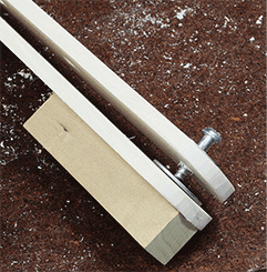
Figure 14-29. The screw joins Arm 2 with Arm 4.
Set aside Arm 2 and Arm 4. It’s time to deal with Arm 1. End A of it is going to be attached to a block of two-by-four which you should cut now, measuring 3½" x 3½" square. Draw an X connecting its corners, to find the center. Drill a 1/8" guide hole in the center that is ¾" deep, and you’re ready to join Arm 1 to it, as shown in Figure 14-30. A 1¼" long, round-headed screw will go through a washer, then through the A end of Arm 1, and through another washer, into the guide hole in the two-by-four. Once again, tighten the screw but then slacken it off by a quarter-turn.

Figure 14-30. Arm 1 will be anchored to the square block.
Cut another block of two-by-four, this time 2" x 2" square. Mark the center, drill a 1/8" guide hole ½" deep, and attach the B end of Arm 1 and the A end of Arm 3, as shown in Figure 14-31, with Arm 3 overlapping Arm 1. This time, because you have two arms, you need three washers, one under the screw head, one between the arms, and one between Arm 3 and the block. The assembly is shown in Figure 14-32. Tighten the screw and then slacken it off by a quarter-turn.
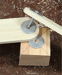
Figure 14-31. Assembling arms 1 and 3.

Figure 14-32. Arm 1 and Arm 3 connected.
You’re almost done. You now have two pairs of arms, and you need to link them using nuts and bolts. Check back to Figure 14-7 to refresh your memory. The bolts in that figure are shown with hex heads.
Lay Arm 2 over Arm 1 and push a ¼" bolt through the holes, with a washer under the head of the bolt, a washer between the arms, and a washer under Arm 1. The bolt may be a tight fit in the ¼" holes, but this is good: you don’t want it to be loose. If you can’t push it through with your fingers, tap it with a hammer, or screw it through with a wrench.
Attach a nut on the underside, grip it with your pliers, and tighten the bolt with your wrench, as in Figure 14-33.

Figure 14-33. Tightening a bolt to connect Arm 2 and 1.
Arms 3 and 4 are connected in exactly the same way. Once again, refer back to Figure 14-7 to make sure you have them connected right.
Now, there’s just one more thing to take care of, which is to drill a hole for the finishing nail that will function as a pointer in the dowel underneath Arm 4. A 1/8" hole should work. Be careful, though, that you don’t drill into the screw that entered the dowel from the other side. This will break your drill bit. Figure 14-34 shows a cross-section side view. Locate the nail hole about ¼" from the end of the dowel. Drill gently, to avoid splitting it.

Figure 14-34. Installing the nail that serves as a pointer in the pantograph.
Mix a little epoxy glue, turn the pantograph upside-down, and dribble the glue into the nail hole. Insert the head of the nail into the glue, and turn the pantograph on its side, as in Figure 14-35. The underside of the large wooden block, the point of the pencil, and the point of the nail should all line up, so that when the pantograph is placed on a table, they will all sit flat and make contact with the table. I used a speed square, as in this figure, to check the adjustment. Then I waited for the glue to set.

Figure 14-35. Aligning the pencil, the nail, and the anchor block.
Using the Pantograph
Figure 14-36 shows the pantograph in action, replicating a drawing at 1.5 times its original size. You’ll notice that the anchor block has been taped to the work surface, along with the original drawing and the paper for the copy.

Figure 14-36. The pantograph replicating and enlarging a drawing of a handsome guy.
Using the pantograph is a little counter-intuitive. You don’t take hold of the pointer. You hold the pencil, and watch the pointer as you move the pencil. You will find, magically, that your pencil is duplicating the art. But why does it work?
How It Works
Check the simplified diagram in Figure 14-37. Arms 1 and 4 of the pantograph must be parallel with each other, and arms 2 and 3 must be parallel with each other. You take care of this by choosing the holes that you use for your two bolts.

Figure 14-37. How a pantograph magnifies a drawing.
It’s fairly easy to prove, geometrically, that the ratio between X1 and Y1 will always be the same as the ratio between X2 and Y2. So, your choice of a hole in Arm 1 determines your magnification ratio. The way I set things up, the bolt is in the hole located 10" from the pivot in the anchor block. So, Y1 = 10. We know that X1 is fixed at 15", so the magnification ratio will be 15 divided by 10 = 1.5.
If you unscrew the bolts and move arms C and D to the left, as in Figure 14-38, now you’re using the 7½" holes, so the magnification is 2:1. If you move C and D another step to the left, you get 3:1, and finally 5:1.

Figure 14-38. Setting the pantograph for 2:1 magnification.
Breaking the Rules
I said that Arm 1 must always be parallel with Arm 4, and Arm 2 must always be parallel with Arm 3. But—what if you break the rules? Suppose you unscrew the nuts and bolts and connect the bolts through randomly selected holes. What do you think will happen?
You’ll find that making the distances unequal will result in an interestingly and strangely distorted copy of the original drawing. Adding distortion is something unique to the pantograph. (A photocopy machine can’t do that.)