
Chapter 17
Another Better Box
Just in case you found the gluing process difficult in Chapter 16, I’m going to show you how to use screws with 1/8" ABS in a way that takes advantage of its uniform texture. Wood grain always tends to push a drill bit or a screw in one direction or another, even when you are working with high-quality hardwood. Because plastic has no grain, it doesn’t create that kind of problem, and you can achieve greater precision, even with a handheld drill.
The screws that I want to use with ABS are tiny, because I plan to insert them into the edge of the 1/8" sheet. Yes, this can be done! But #2 screws are uncommon, and you will probably have to order them online. I suggest stainless steel, because in my experience they have sharper threads and are better made. They are not expensive.
Assuming your screws have Phillips heads, you need a miniature size 1 Phillips screwdriver. A hardware store may not stock this as a separate item, but it should be included in a set such as the one shown in Figure 17-1.
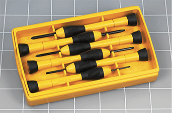
Figure 17-1. A set of miniature screwdrivers including the Phillips size 1 that you need for this project.
As you might imagine, #2 screws are thin—just under 3/32" in diameter, including the threads. But a 1/8" piece of plastic is thicker than that. How much thicker? Let’s figure it out. 1/8" is the same as 4/32", so if you could insert a 3/32" screw in the edge of a piece of 1/8", the screw would allow 1/64" of plastic to remain either side of it. Not a whole lot, but, it can work.
What about a pilot hole? In my experience a #2 screw grips quite well in a 5/64" hole when you are using it with ABS. Can you drill that hole in the edge of a 1/8" sheet? Figure 17-2 suggests that it should be possible.

Figure 17-2. How a pilot hole can be drilled into the edge of 1/8" plastic.
So much for the theory. If this sounds too ambitious, bear in mind you can scale up the whole project. You can use ABS that is 3/16" thick instead of 1/8", and multiply all the dimensions by 1.5. The screws that hold it together should be 1.5 times as long, but they don’t need to be 1.5 times thicker. Or you can go all the way to ABS that is ¼" thick.
On the other hand, bear in mind, I am not a highly skilled crafts person. In fact, for my whole life, I have had a slight tremor in my hands. I tend to think that if I can build this, you can probably build it too.
To find out, let’s try a feasibility study.
An ABS Test
You should have some small pieces of scrap ABS left over from the previous box. One of them can be clamped vertically, in an arrangement such as that in Figure 17-3. ABS is so soft in comparison to a steel bit, you don’t need to mark the edge of the ABS with an awl. The bit will start the hole easily, and you can tell if it is centered on the edge of the plastic just by looking at it.

Figure 17-3. Clamping a piece of scrap ABS for a feasibility test.
Put a 5/64" bit in your drill, and run the drill as slowly as possible, so that the bit is barely turning. Touch the tip of it where you want the hole to be, and adjust it a little each way till it’s centered. The bit should make an indent such as the one shown in Figure 17-4.

Figure 17-4. Starting a hole in the edge of the sheet.
If the indent isn’t centered, abandon that location and try again further down the edge. But if the indent does seem to be centered, you’re ready to make the actual hole. Check that your drill bit is exactly parallel with the vertical sides of the ABS, and press a little harder, while still running the drill very, very slowly. Keep your hands out of the way of the drill bit, in case it breaks through the side of the plastic.
Because ABS has no grain, there’s nothing to push the drill off its track. The hole will make itself, and it only needs to be ½" deep. Little threads of ABS will come out, as in Figure 17-5. Remember that this is a 5/64" drill; the photograph was taken with an extreme closeup lens.

Figure 17-5. Drilling in progress.
The finished hole should have well-defined edges, as in Figure 17-6.

Figure 17-6. The finished hole.
Take another scrap piece of ABS and mark two lines 1/16" apart on its smooth side, parallel with an edge and 1/16" away from it, as in Figure 17-7. A pen line may be too thick to do this accurately, so I used a pencil. Because it’s more difficult to judge the position of a drill bit on a wider surface, I made a mark with an awl.
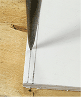
Figure 17-7. Two parallel pencil lines, separated by 1/16”.
You need to make a screw hole on the center line. Use the same 5/64" bit, because the next size up will be too big. Figure 17-8 shows the hole being drilled, and Figure 17-9 shows the hole finished.
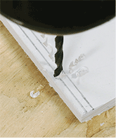
Figure 17-8. Making the screw hole.

Figure 17-9. The screw hole complete.
Now you need to countersink the hole, as you’ll be using a flat-headed screw. Turn the sheet over, as the textured side is usually the outside of any object that you build with ABS. The countersunk hole is shown in Figure 17-10.

Figure 17-10. The hole after countersinking.
You’ll notice that the beveled edge has broken through the edge of the plastic. I’ll deal with this issue in a moment.
Using your miniature screwdriver, drive a #2 screw into the hole that you just made. It’s not a wood screw, so its thread will pull it all the way in. When its head is flush with the surface of the ABS, keep turning the screwdriver, and the threads at the top of the screw will round out the inside of the hole. The screw starts turning freely—just as if it had a smooth shank.
Insert the tip of the screw in the first hole that you drilled, and the threads will bite just enough to pull the screw in, without breaking through the outer surface of the plastic or even making it swell visibly. But if you over-tighten the screw, it will strip the threads. A gentle touch is needed. See Figure 17-11.

Figure 17-11. A Philips #1 screwdriver is necessary to fit the #2 screw.
The pieces of plastic joined with a screw are shown in Figure 17-12. But, you see the problem. The screw head is a little too wide, and overlaps the edge of the plastic. Does it matter? That depends. When I’m making something small that is supposed to look very precise, I like everything to be just right. In any case, I’m not sure screws look good so close to the edge. So I designed a jewelry box with the sides recessed, as shown in Figure 17-13. I think the screws look nicer that way.

Figure 17-12. The screw head doesn’t quite fit inside the edge.

Figure 17-13. A rendering of the jewelry box.
Box Design
The box is shown with its lid open in Figure 17-14, and with some of the parts separated in Figure 17-15.
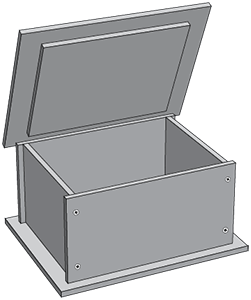
Figure 17-14. The box with its lid open.

Figure 17-15. The parts separated and identified.
The other projects that I have described in this book didn’t attempt to be stylish, because everything has to be simple when you’re learning the basics. In this one I tried to make it a little more visually interesting. Also, by extending the base outward and standing the sides of the box on it, I was able to hide four more screws, which are under the base, going up into the side pieces.
Inevitably, when something looks more visually interesting, it requires a little more work. This box requires nine pieces of plastic, to be cut out of two strips of differing widths. On the other hand, you won’t have to struggle with solvent cement.
The pieces that you need to cut are shown in Figure 17-16, with letters that refer back to Figure 17-15.

Figure 17-16. Pieces of plastic to cut and drill.
To make pieces in the top row, cut a strip 2¾" wide in the same way as in Chapter 16, and then cut the width of each piece out of it in your miter box (remembering to make two copies of the one labeled E and F). Then trim pieces A and B to the right height.
For pieces in the lower row, use a strip of plastic 4½" wide, then cut the width of each piece out of it (remembering to make two copies of each), and trim the pieces labeled G and H to 4" high. My miter box is just wide enough for a 4½" strip; I hope yours is, too.
Next drill the holes in pieces B, G, and H. I suggest you mark the locations on the smooth side, and drill through to the textured side. Making marks, and cleaning them later, will be easier on the smooth side. Because all the pieces are symmetrical, you can turn them over later if this is required by the assembly process.
Countersink each hole on the textured side. Don’t drill piece C yet. Just mark where the holes are supposed to be. The locations may have to be adjusted slightly.
Begin assembly with piece H, the front of the box and a side of the box, such as E. In Figure 17-17, piece E has been clamped vertically to the side of a two-by-four, which is clamped to the work area. Align piece H with piece E, and with a sharp pencil, mark through the screw holes to establish locations for pilot holes.

Figure 17-17. Marking the locations for pilot holes.
Set the longer piece aside, and drill 5/64" pilot holes where you see the pencil marks, as in Figure 17-18.

Figure 17-18. Drilling pilot holes.
After the screws have been inserted, the two pieces are shown joined together in Figure 17-19.

Figure 17-19. The first two pieces, joined.
Use the same procedure to add more pieces, and you’ll find that the sides of the box are just far enough apart to straddle a two-by-four, as in Figure 17-20.
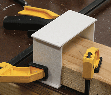
Figure 17-20. Continuing to assemble the box.
When you have joined all four sides, stand them on the base, which should be smooth-side up. Measure the margins around the sides of the box, to check that they are centered. Look to see whether the locations for the screws through the base will match the positions of the sides. Draw around the inside and outside of the box with a pencil, if this will help to clarify the situation. Relocate the hole positions slightly, if necessary, and then make your holes through the base.
Turn the box over, and rest the base on it. Make pencil marks through the holes that you drilled, then remove the base and drill pilot holes, with the box clamped as in Figure 17-21.

Figure 17-21. Pilot holes to match screw holes in the base.
Install screws temporarily in the first two holes, as shown in Figure 17-22, to stabilize the assembly while you mark the remaining two holes.

Figure 17-22. Marking the remaining two pilot holes while the base is temporarily held in place.
You may find that some of the screw holes don’t line up precisely with your pilot holes, although this is less likely to happen with ABS than it was with plywood, because ABS doesn’t contain grain that pushes your drill off track. Fortunately ABS is so soft and flexible, if a screw doesn’t quite line up, the screw hole will widen slightly to allow the screw to go in anyway.
You may remember that in Chapter 10, you measured all the positions of pilot holes, and drilled them before assembly. That was a learning experience, demonstrating the difficulty of doing precise work, especially with plywood. In this project, marking through a screw hole to the position of a pilot hole should make the process of assembly easier.
The last two screws will attach the handle to the top surface of the lid. Drilling pilot holes in the handle requires careful clamping, as in Figure 17-23.

Figure 17-23. Drilling pilot holes in the handle.
But, it can be done. See Figure 17-24.

Figure 17-24. Completed pilot holes in the handle.
Check the bottom layer of the lid (piece D) to see if it will fit within the sides of the box, and sand it down as much as necessary, as you did with the glued box in Chapter 16. When it fits easily, you need to assemble the three layers of the lid. This isn’t possible with screws, because the layers of the lid aren’t thick enough for you to sink screws into them. You need to use solvent cement, which is easy on such a wide, flat area. I placed masking tape to indicate where each piece should be glued, as in Figure 17-25.

Figure 17-25. Masking tape shows where to place the top of the lid when it is glued to the middle layer of the lid.
When dribbling cement onto a flat surface, be careful to place the surface horizontally. Otherwise the cement will run off, with unexpected consequences. Remember to use eye protection and hand protection during the gluing process, and work in a well-ventilated area.
The finished jewelry box is shown in Figure 17-26.

Figure 17-26. The finished jewelry box, with four visible screws and four hidden screws. Do the screws spoil its appearance?
I tend to think that something small can look more attractive than something big, even though it may be built in the same way. Screws and butt joints look okay to me on the scale of the jewelry box, especially because the edges of ABS don’t have the rough, splintery look of plywood.
I have to admit, though, that fabricating larger objects is easier. The main reason I specified 1/8" ABS for this project is that I like to use the same materials in multiple projects, and 1/8" was quick and easy to bend in Chapter 15.
So far, I have only used ABS, but of course there are many other plastics that you can use, especially if you want transparency. The next chapter shows you some examples.