Chapter 15
Fur, Hair, and Clothing
The Autodesk® Maya® software offers a number of tools for adding fur, hair, and clothing to characters. Creative use of these tools adds believability and originality to your animated characters. In addition, many of these tools can be used to create engaging visual effects. This chapter takes you through a number of techniques that you can use to add fur, hair, and clothing to characters.
In this chapter, you will learn to:
- Add fur to characters
- Add dynamic motion to fur
- Create dynamic curves
- Add hair to characters
- Style hair
- Use hair constraints
- Paint nCloth properties
Adding Fur to Characters
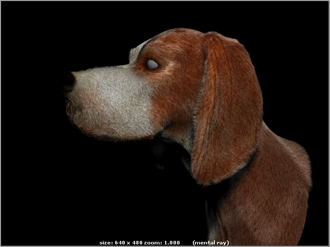
In this section, you’ll add Maya Fur to a model of a hound dog’s head. Maya Fur can be used on NURBS, polygon, and subdivision surfaces. There are some limitations when using NURBS and subdivision surfaces. For instance, rendering fur on trimmed NURBS surfaces can add to render time, and many of the paintable fur attributes do not work when using subdivision surfaces. For this reason, we recommend that you use polygon geometry whenever possible.
Maya Fur works best for short-haired characters or characteristics such as eyebrows and facial hair. Think about using fur for hair that would be two inches or shorter in the real world. If your character’s hair is longer than that, then consider using Maya Hair, or Paint Effects.
Preparing Polygons for Maya Fur
Polygon models need to have properly mapped UV coordinates that lie within a 0 to 1 range in texture space. You should make sure that there are no overlapping UVs. This can cause problems and may even crash Maya when rendering.
Try to maintain consistency in texture space as you create UV coordinates. Seams between separate UV shells and between parts of the model’s texture coordinates are easily seen in the distribution of fur across the surface, and they can be difficult to eliminate. Figure 15-1 shows an example of a visible seam in the fur attached to the hound dog model. This seam appears because the end of the nose is a separate shell from the rest of the hound’s head. In some cases, it may be impossible to eliminate all seams.
The best strategy is to place UV seams on parts of the surface that are less noticeable than others. Once you have an understanding of how fur works after completing this chapter, you should test a simple fur preset (such as the duckling preset found in the Visor) on your models as you map the UV texture coordinates. You’ll see where the problem areas are before you spend a great deal of time perfecting the fur itself. Props such as clothing can also be used strategically to hide UV seams.
Chapter 11, “Texture Mapping,” has detailed information on how to create UV texture coordinates for polygon models.
Using the Example Scenes
Maya Fur relies heavily on file textures that are saved in the
fur subfolders of the current project. If you intend to use the example scenes in this chapter, you should copy the entire
Chapter 15 project folder from the book’s web page (
www.sybex.com/go/masteringmaya2014) to your local disk. This should ensure that the results you get when you test the example scenes are consistent with what is presented in the figures in this book.
In this example, the hound model has been created and the UVs have been properly prepared.
1. Open the hound_v01.ma scene from the chapter15scenes folder.
2. Select the houndHead model, and choose Window ⇒ UV Texture Editor.
The UVs for the houndHead model are displayed in the UV Texture Editor (see Figure 15-2).
If you are applying fur to a subdivision surface, you may want to convert the model to polygons first and prepare the UVs before applying the fur. You can convert the model to subdivision surfaces after the fur has been applied. Working with subdivision surfaces and polygons is covered in Chapter 4, “Modeling II.”
Creating a Fur Description
The fur description node contains all the settings for the fur, such as length, color, width, density, and so on. A single fur description node can be applied to more than one surface.
A number of preset fur descriptions are available on the Fur shelf or by clicking the Presets button in the Attribute Editor for the fur description node. You can use a preset as a starting point. In this exercise, you’ll build the fur description from the default fur settings.
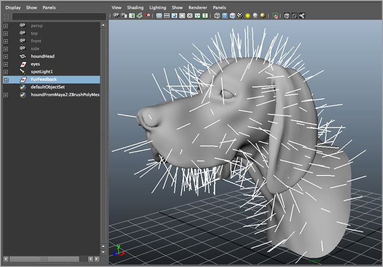
1. Select the houndHead model. Switch to the Rendering menu set, and choose Fur ⇒ Attach Fur Description ⇒ New.
The houndHead surface is covered in long spikes. These spikes are a preview that approximates how the fur will look on the surface. This approximation is a visual aid you can use while editing the fur. If you do not see the spikes (see
Figure 15-3), the display of locators may have been disabled in the Viewport window. To fix this, choose Show ⇒ Locators from the menu in the Viewport window.
You can find the controls for the fur preview in the Attribute Editor for the houndHead_FurFeedbackShape node. This node is parented under the FurFeedback node in the Outliner.
2. In the Outliner, expand the FurFeedback group and select the houndHead_FurFeedback node.
3. Open the Attribute Editor, and click the houndHead_FurFeedbackShape tab.
4. To increase the number of fur strands displayed in the viewport, set U Samples and V Samples to 128.
You can set these values higher for a more accurate display; however, higher settings will slow the performance of Maya on your computer. The U and V Samples affect only how the fur is displayed in Maya; they do not affect how it will look when rendered.
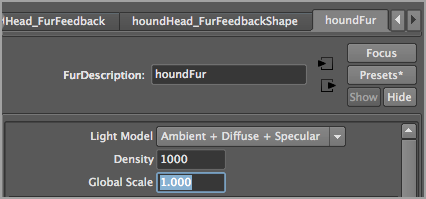
5. Switch to the FurDescription1 tab in the Attribute Editor. Here you’ll find the settings that determine how the fur will look when rendered.
6. In the Fur Description field, rename FurDescription1 to houndFur.
7. Save the scene as hound_v02.ma.
To see a version of the scene up to this point, open the hound_v02.ma scene from the chapter15scenes folder at the book’s web page.
Editing the Fur Description: Baldness
There are several ways to design the look of fur applied to your model. You can adjust the slider settings in the fur description node to create an overall look for the fur, or you can apply texture maps to the fur settings. These texture maps can be procedural nodes (such as ramp, fractal, or checker), or they can be file textures painted in other programs. You can also use the Artisan Brush tool to paint settings directly on the model. In this section, you’ll use Artisan to determine where fur grows on the model.
Fur is applied uniformly across the surface of a model. To control exactly where the fur grows, you’ll use the Baldness attribute. The Baldness value ranges between 1 and 0. The confusing aspect about the Baldness setting in particular is that a setting of 1 means fur covers the surface. A setting of 0 means the fur does not grow at all. This is confusing because intuitively more baldness (higher values) should mean less fur. In Maya, the settings are reversed so that a higher Baldness values mean more fur. Fortunately, this is the only setting that suffers from this counterintuitive behavior.
Settings between 0 and 1 determine the sparseness of the fur. Using a low Baldness setting, such as 0.1 or 0.2, might work well when creating whiskers for a man’s face.
In this exercise, you’ll apply Baldness values so that fur does not grow on the end of the nose, in the eye sockets, or on the inside of the mouth.
1. Continue with your scene, or open the hound_v02.ma scene from the chapter15scenes folder.
2. In the Outliner, select the houndHead_FurFeedback node parented to the FurFeedback group.
3. In the Attribute Editor, select the houndFur tab.
4. Set the Base and Tip Color attributes to bright red. This makes it easier to see the fur as you paint attribute maps. If the fur does not turn red when you adjust the sliders, make sure that Color Feedback Enabled is turned on in the houndHead_FurFeedbackShape node.
5. Switch to the houndFur tab. To make it easier to see what’s going on, set the Length value to 0.1. This reduces the overall length of the fur. Later you’ll fine-tune the length of the fur on the model using Artisan.
6. Move the Baldness slider back and forth between a value of 1 and 0. You’ll see the fur become sparser when the value is lower.
The slider works well to establish an overall value. For precise control, you’ll paint Baldness values directly on the model.
Fur Global Scale
You can also reduce the length of the fur by reducing the Global Scale value (as shown here). However, refrain from adjusting this slider when you first edit a new fur description, because the slider should be used to keep all the fur settings consistent when the model itself is scaled. For example, if this model and its fur are imported into a scene that requires the model to be resized, you can adjust the Global Scale value of the fur based on the scaling values applied to the model, and the look of the fur should remain consistent when rendered. If you adjust Global Scale before designing the fur, it may make it hard to adjust the settings properly if the model is scaled.
7. Set the Baldness slider to 1 so that the fur covers the entire model evenly.
8. In the Outliner, select the houndHead object. Choose Fur ⇒ Paint Fur Attributes Tool ⇒ Options. The tool options open on the left side of the screen by default at the same time a small pop-up menu appears. If Maya stops for a moment, don’t be alarmed; it is preparing the model for painting.
9. In the Paint Fur Attributes Tool Settings pop-up, make sure that the Fur Attribute is set to Baldness and the Fur Description is set to houndFur.
10. Set Attribute Map Width and Height to 1024.
11. In the options for the Artisan Brush, set Paint Operation to Replace and Value to 0. Wherever you paint on the surface of the model, fur will be removed.
Attribute Map Resolution
The Attribute Map Width and Height determine the resolution of the baldness map that will be created when you use the Paint Fur Attributes tool. In the case of the hound model, you’ll need a higher resolution so that you can paint Baldness values around the areas of the eyes, nose, and lips more precisely. If the attribute you are painting does not require precision, you can use lower values for Height and Width.
12. In the Tool Settings dialog box, under the Display rollout panel, activate Color Feedback. This colors the model according to the values you paint on the fur. The colors act as a guide as you paint.
13. Zoom in on the nose of the model. Hold the cursor over the nose of the hound. Hold down the b key, and drag left or right to adjust the width of the brush interactively.
14. Start painting in the nose; you’ll see the spikes start to disappear as you paint. The area you paint also turns black (see
Figure 15-4).
Sometimes you need to paint over a spike a couple of times to get it to update. If you need more detail, in the FurFeedback node you can increase the U and V Samples values on the houndHead_FurFeedbackShape tab.
Map File Update
As you paint, Maya creates a temporary map file for the Baldness attributes. Occasionally Maya pauses as it updates the file. Ideally this should not happen too often. If Maya appears to freeze while working, don’t be alarmed. Give it a few moments to think while it’s updating the fur file.
If you get no reaction from the Paint Fur Attributes tool at all, try unselecting and reselecting the houndHead surface in the Outliner. The Paint Fur Attributes tool works only when the surface object is currently selected, so it won’t work if just the fur nodes are selected.
15. Paint on the nose and the inside folds of the nose until all the fur spikes are gone. You’ll edit the Baldness values more later, so don’t stress out if it’s not absolutely perfect.
16. When you have finished the nose, use the Show menu in the perspective view to turn off the visibility for NURBS surfaces. The eyes disappear. Paint inside the eye sockets to remove the fur from inside the eye sockets (see
Figure 15-5).
17. To remove fur from the lips, you can move the perspective view inside the model and paint on the back side of the surface (see
Figure 15-6).
18. In the Attribute Editor for the houndFur node, scroll down and expand the Details section.
19. Find the Baldness rollout panel, and expand the Maps section. This lists the maps painted for the houndHeadShape. Currently the baldness map is listed as UNNAMED. This refers to the map you have been painting on the hound. It exists as a temporary file until you save the scene (see
Figure 15-7).
20. Save the scene as hound_v03.ma.
When you save the scene, the maps that you have painted for the fur attributes are saved to disk. You can find them in the current project’s furfurAttrMap folder. The maps are saved in the Maya IFF format.
If you reopen the scene, the UNNAMED label is replaced in the Maps section of the Attribute Editor for the houndFur node with the path to the baldness map that has been saved to disk (see Figure 15-8).
Editing Map Files
Maps listed in the Details section of the fur node are always image files (as opposed to procedural textures such as ramp, fractal, or checker). You can edit these images in the Autodesk® Mudbox® program or programs such as Photoshop and ZBrush. After editing the image, click the map button under the Details ⇒ Maps section of the painted attribute and use the dialog box to select your image.
Editing the Fur Description: Direction
You can use the Artisan Brush interface to comb the fur by painting the Direction attribute:
1. Continue with the scene from the previous section, or open the hound_v03.ma scene from the chapter15scenes folder at the book’s web page.
You’ll notice that there is no Direction or Comb attribute listed in the attributes for the houndFur node. Painting the Direction attribute is the same as painting the Polar attribute.
2. In the houndFur node’s Attribute Editor, set Inclination to
1, and move the Polar slider back and forth. The Polar slider determines the direction in which the fur strands face, but you’ll notice that the direction is not uniform across the surface. The following attributes also control the direction of the fur:
Inclination Sets the angle at which the hair stands from the surface. A value of 0 is perpendicular to the surface; a value of 1 causes the fur to lie flat against the surface. If the value is 0, then the fur strand sticks straight up, so changing its direction has no visible effect.
Roll Rotates the fur around its root. A value of 0 is –90 degrees; a value of 1 is 90 degrees.
Base Curl and Tip Curl Determine the amount of curling applied to the base and tip of the hair. A value of 0.5 produces straight hair; a value of 0 or 1 curls the hair from one side or the other.
The change in direction created by the Polar attribute is based on the direction of the UV texture coordinates. This means that a value applied to fur on one part of the model has a different result than a value applied on another part of the model. To comb the hair correctly, you use the Direction attribute in the Paint Fur Attributes tool to apply a Polar value based on the direction that you drag across the surface. So when you choose to paint the Direction attribute in the Paint Fur Tool options, you’re really painting values for the Polar attribute but in a way that is a bit more intuitive.
When painting the direction, set Inclination to a value other than 0, and the Roll value must be something other than 0.5. The Base Curl and Tip Curl values must be something other than 0.5 as well. If these values are not set properly, painting the Direction has no effect. In addition, Color Feedback has no bearing on the direction of the fur, so you can turn this option off in the options for the Artisan tool.
3. Open the Attribute Editor for the houndFur node, and use the following settings:
Inclination: 0.8
Roll: 0.2
Base Curl: 0.7
Tip Curl: 0.3
4. Select the houndHead surface. Choose Fur ⇒ Paint Fur Attributes Tool ⇒ Options. Wait a few moments for Maya to update.
5. In the Tool Settings dialog box for the Artisan tool, scroll to the bottom. In the Display options, turn off Color Feedback.
6. In the pop-up options for the Paint Fur Attributes Tool settings, set Fur Attribute to Direction. Make sure Fur Description is set to houndFur and Attribute Map Width and Height are set to 1024. The Paint Operation or Value settings in the Artisan options do not affect how the fur is combed.
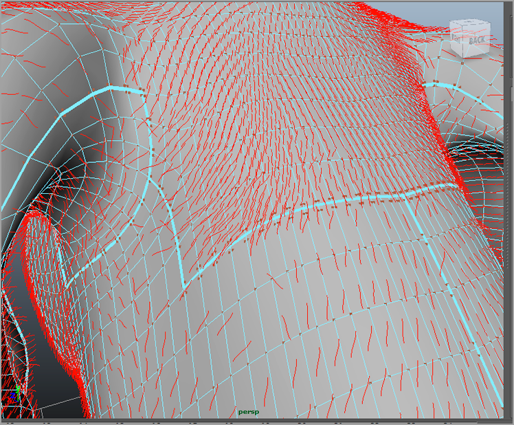
7. Drag across the surface to push the fur in the general direction you want it to go. Use
Figure 15-9 for reference.
Figure 15-10 shows how the paint stroke influences the direction of the fur on the model.
Paint lightly and slowly using repeated strokes to make the fur point in the desired direction. If you are painting with a mouse, lower the Opacity value to mimic a light brush stroke. Combing the fur requires some patience and practice. It’s helpful to increase the U and V samples on the FurFeedback node so that you can see more fur as you are painting. It can be difficult to maintain a consistent direction across UV seams. The fewer seams you have in your UV texture coordinates, the easier it will be to paint the direction of the fur.
The Direction attribute responds to the direction in which you move the cursor over the surface.
8. Save the scene as hound_v04.ma.
To see a version of the scene up to this point, open the hound_v04.ma scene from the chapter15scenes folder.
Painting Across UV Texture Borders
As you paint across UV borders on the model, you’ll see the hair suddenly flip around. Since fur relies on UV texture coordinates to determine how the Polar attribute affects direction, as you move from one part of the texture space to another the polarity of the fur can suddenly change (a good example of this occurs on the back of the hound’s head). This may drive you crazy. To help deal with these problems, select the model, and choose Display ⇒ Polygons ⇒ Texture Border Edges. This makes the border edges of the UV coordinates visible as bold lines on the surface of the model. You can also reduce the size of the brush so that you can more easily paint specific areas along the border. With some patience and work, you’ll be able to make the direction of the fur consistent across the UV texture border.
Editing the Fur Description: Length
You can edit the Length attribute using the Paint Attributes tool as well. When editing lengths, you need to pay attention to the values used in the options for the Artisan Brush. For the hound, the fur is short near the end of the nose, is medium length on the face, and is long on the back of the head and neck. Values of 0.1, 0.25, and 0.5, respectively, were used on the aforementioned areas. To even out the transition between the fur lengths, set Paint Operation to Smooth, and paint the areas on the border between the different lengths of fur.
To see a version of the scene up to this point, open the hound_v05.ma scene from the chapter15scenes folder.
After painting fur lengths, you may decide to touch up the Direction attribute of the fur as well. You can change the paint operation mode (from Length to Direction, for example) in the Paint Fur Attributes Tool Settings pop-up whenever you need to, but remember that Maya may pause for a few moments to update the maps when you change attributes.
Baking Textures into Maps
You can use a procedural texture node (such as a ramp, fractal, or checker) as a starting place for a fur attribute map, as shown here. This works well when you are painting fur applied to a NURBS surface, since the UV texture coordinates are based on the parameterization of the surface itself. If you create a texture by clicking the Create Render node icon, you will need to bake the attribute before seeing the results. To do this, open the Attribute Editor for the FurDescription node. Set the Bake attribute to the desired attribute, and click the Bake button.
To see the Bake attribute in action, open the rampBaldness.ma scene from the chapter15scenes folder at the book’s web page.
A good use for this technique would be to apply fur as grass to a NURBS plane. You can use a fractal texture to create procedural variation in baldness or length to make the grass appear patchy.
Test-Render Fur
Now that you have the basic fur description created for the houndHead, you may want to see what it looks like when rendered. You can render the scene using either the mental ray® or Maya Software. The results should be fairly similar. In this example, you’ll use mental ray:
1. Continue using the scene from the previous section, or open the hound_v05.ma scene from the chapter15scenes folder.
2. Open the Render Settings window, and set the Render Using menu to mental ray.
3. On the Quality tab, set Quality Presets to Production: Rapid Fur (see
Figure 15-11). This preset uses the Rasterizer as the primary renderer instead of raytracing. For more information on rendering with mental ray, consult Chapter 12, “Rendering for Compositing.”
4. Open the Render View window, and create a test render using the perspective camera.
You’ll notice immediately that the fur does not look realistic (see the upper-left image in
Figure 15-12). It is sparse and bright red. You need to increase the Density setting of the fur so that enough hair covers the surface of the model.
5. Set Density in the houndFur tab to
100,000, and create another test render (see the upper-right image in
Figure 15-12).
The fur is much denser without adding too much to the render time. To improve the look of the fur, you can edit the base and tip widths as well as the basic color.
6. In the houndFur tab in the Attribute Editor, click the color swatch next to Base Color and use the Color Chooser to set the color to a dark brown.
7. Set Tip Color to a light brown.
8. Make sure Base Opacity is set to 1, and use the following settings:
Tip Opacity: 0.1
Base Width: 0.01
Tip Width: 0.005
9. Create another test render (see the lower-left image in
Figure 15-12).
10. Raise Density to
500,000, and create another test render (see the lower-right image in
Figure 15-12).
11. Save the scene as hound_v06.ma.
To see a version of the scene, open the hound_v06.ma scene from the chapter15scenes folder.
The fur should cover the model completely; however, you will notice that some attributes, such as the baldness map and the direction, may require further editing.
Applying a Color Map
Adding a texture map to the color greatly helps the realism of the fur. You can increase the efficiency of the render by applying the same file texture to the fur color and the shader as applied to the model. This technique should work as long as the model does not get extremely close to the camera.
A texture map that has been carefully painted in Photoshop or in a 3D texturing program works better than a map created by painting color on the fur. In this case, ZBrush was used to create the color texture map for the hound model.
1. Continue with the scene from the previous section, or open the hound_v06.ma scene from the chapter15scenes folder at the book’s web page.
2. Open the Hypershade, select the houndShader material, and open its Attribute Editor.
3. Click the checkered button next to the Color channel to open the Create Texture Node window.
4. Click the File button to create a file texture node.
5. In the Attribute Editor for the file1 node, click the folder icon next to Image Name.
6. Use the browser to select the houndBaseColor file texture from the chapter15sourceimages folder at the book’s web page.
7. Press the 6 key to switch to textured view so that you can see how the color is placed on the model.
8. Keep the Hypershade window open. In the Outliner, expand the FurFeedback group and select the houndHead_FurFeedback node.
9. In the Attribute Editor, select the houndFur tab.
10. In the Hypershade, switch to the Textures tab. MMB-drag the file1 texture onto the Base Color swatch in the Attribute Editor for houndFur (see
Figure 15-13).
11. In the Hypershade, create a second file texture node (Create 2D Textures ⇒ File).
12. In the Attribute Editor for file2, load the houndTipColor texture. This is a lighter, less saturated version of the base color.
13. Attach this file to the Tip Color channel in the houndFur node.
14. Lower Specular Color to a dark gray, and set Specular Sharpness to 80. This makes the specular highlight on the fur smaller and less reflective.
15. Set the Density value of the fur to
250,000 in the houndFur tab, and create a test render (see the left image in
Figure 15-14).
16. To increase the realism of the fur, turn on shadows for the scene lights:
a. Select the spotlight1 object, and open its Attribute Editor.
b. Under Shadows, turn on Use Depth Map Shadows.
c. Set Resolution to 1024, and turn off Use Auto Focus.
d. Create another test render (see the right image in
Figure 15-14).
17. Save the scene as hound_v07.ma.
To see a version of the scene, open the hound_v07.ma scene from the chapter15scenes folder.
Applying Map Offsets and Multipliers
In the Details section of the houndFur node, you’ll notice that each attribute has Map Offset, Map Multiplier, Noise Amplitude, and Noise Frequency settings. These sliders can apply an additional adjustment to the fur map attributes.
The Map Offset and Multiplier attributes are used to change the range of values for any of the attributes. Most of the attributes are limited to a range between 0 and 1, which corresponds to the grayscale values painted on the surface with the Paint Fur Attributes brush. If you would like to change the range so that it can go beyond 1, you can use Map Offset or Map Multiplier.
Offset adds a number to the overall range. If you want to offset the range for an attribute so that, instead of a range of 0 to 1 the range becomes 2 to 3, set Offset to 2.
If you want to expand or diminish the range of values, use Multiplier. For example, if you want the range of a value to be between 0 and 10 instead of 0 to 1, set Multiplier to 10.
The Noise Amplitude and Frequency sliders add randomness to the map values.
1. Continue with the scene from the previous section, or open the hound_v07.ma scene from the chapter15scenes folder.
The fur for the hound is a little too long to be appropriate for a typical foxhound. Rather than repaint the Length values, you can simply adjust the Multiplier for the Length attribute.
2. Open the Attribute Editor for the houndFur node, and expand the Details ⇒ Length rollout panel.
3. Set Map Multiplier to 0.5.
4. Expand the Tip Ambient Color attribute, and set Noise Amplitude to 0.5 and Noise Frequency to 25. This adds variation to the brightness of the fur tips.
5. Make sure that the texture maps are properly connected in the houndFur tab and on the shader.
6. Create a test render from the perspective camera (see
Figure 15-15).
7. Save the scene as hound_v08.ma.
To see a version of the scene, open the hound_v08.ma scene from the chapter15scenes folder.
Enhancing the Realism of Fur
The basic fur description for the hound has been created, but to make it look realistic, a fair amount of editing still needs to be done. There are many additional attributes you can use to help accomplish this. This section describes how these attributes work. As with the Baldness, Length, Direction, and Color attributes, you can use a single value to determine the overall setting for each attribute, paint values for the attribute on selected areas, or use a texture map to determine the strength of the selected values.
Inclination, Roll, and Polar are attributes that determine the direction that the fur is pointing along the surface of the model. As noted, Inclination determines whether the hair points straight up from the surface (at values closer to 0) or lies along the surface (at values closer to 1). The Roll setting rotates each hair around the base, and the Polar attribute determines the direction the fur points along the surface. Roll and Polar can be used together to fine-tune the direction of the hair. If you have painted a map for the Direction attribute using the Paint Fur Attributes tool, changing the Polar setting has no effect.
After painting a map for the Direction attribute using the Paint Fur Attributes tool, you may want to paint values for the Inclination and Roll attributes. This can help define more exactly the direction in which the fur points along the surface. You may find yourself switching back and forth among Direction, Inclination, and Roll as you edit the fur on the surface. If you need precise control over the styling of the fur, be prepared to spend some time working with these attributes.
Base Opacity and Tip Opacity are self-explanatory attributes. The base of the fur is the part of the fur strands closest to the surface; the tip is the part of the fur farthest from the surface. Opacity is applied as a gradient across the length of the fur. To create the look of soft, fine fur, set Base Opacity to 1 and Tip Opacity to a very low setting or even 0. You can experiment with these values to create special effects; try a low Base Opacity and a high Tip Opacity.
Base Width and Tip Width establish the shape of the fur strands. A small Tip Width coupled with a large Base Width produces a pointy shape for the fur. A very low Tip Width helps create the look of soft, fine fur.
The Base Curl and Tip Curl attributes add curl to the fur strands at the base or tip. A value of 0.5 produces no curling. A value of 1 or 0 produces curling in one direction or the other.
The Scraggle, Scraggle Frequency, and Scraggle Correlation attributes add random kinks to the hair to create a messy appearance. The Scraggle setting determines the strength of the scraggle. Scraggle Frequency determines how many kinks appear in each strand of fur. Scraggle Correlation determines how the Scraggle value of one strand affects another. A setting of 0 for Scraggle Correlation creates random kinks throughout the fur strands, and a Scraggle Correlation of 1 means all the fur strands kink the same way, creating a wavy appearance for the fur.
The Clumping, Clumping Frequency, and Clump Shape settings cause the fur strands to attract each other into bunches on the surface. This is useful for making a surface appear wet or matted. The Clumping setting sets the strength of the clumping, and Clumping Frequency determines the number of clumps created across the surface. Clumping Frequency ranges between 0 and 100; higher values take longer to render. Clump Shape determines whether the clumps themselves are convex or concave. Settings closer to –10 produce concave clump shapes, whereas settings closer to 10 produce convex clumps (see Figure 15-16).
Rendering Fur Using mental ray
You can render fur using mental ray or Maya Software. When rendering with Maya Software, you’ll need to add a fur-shadowing node to the lights in the scene. In this section, you’ll learn how to refine the look of the fur with mental ray.
If you plan to use depth map shadows, use the Production: Rapid Fur preset. If you plan to use raytrace shadows, use the Production: Fine Trace Render preset. If you need the fur to appear in reflections or refractions, use raytracing.
Fur renders use indirect lighting techniques such as Final Gathering. Be aware that the render times for dense fur descriptions when Final Gathering is enabled can be quite long.
To create a realistic render of the hound using raytracing, follow these steps:
1. Continue with your scene file or open the hound_v08.ma scene from the chapter15scenes folder.
2. Open the Hypershade, and select the houndShader material.
3. In the attributes for the material, set the Diffuse attribute to 1. Increasing the Diffuse quality of the shader can sometimes help blend the surface material with the color of the fur.
4. Open the Render Settings window, and select the Quality tab. Set Quality Presets to Production: Fine Trace.
5. In the Outliner, select the spotlight, and open its Attribute Editor.
6. Under Shadows, turn on Use Ray Trace Shadows.
The Fur/Shadowing attributes listed below the Use Ray Trace Shadows settings are used specifically when rendering with Maya Software, which requires that the shadow-casting lights be connected to the fur description. This is not necessary when rendering with mental ray.
7. Create a directional light. Rotate the light so that it is shining toward the camera. This creates nice fill lighting as well as a fringe of light along the edge of the fur.
8. In the settings for the directional light, turn off Emit Specular and set Intensity to 0.8.
9. In the Outliner, expand the FurFeedback group and select the houndHead_FurFeedback node. In the Attribute Editor, click the houndFur node.
10. Set Density to 500,000. Scroll down to the list of Attributes. Set Tip Opacity to 0 and Base Opacity to 0.5. This helps soften the look of the fur.
11. Set Base Width to 0.008 and Tip Width to 0.001.
12. Create a test render from the perspective camera. The scene takes between 5 and 8 minutes to render, depending on your machine (see
Figure 15-17).
13. Save the scene as hound_v09.ma.
To see a finished version of the scene, open the hound_v09.ma scene from the chapter15scenes folder at the book’s web page.
You can continue to enhance the look of the fur by improving the texture maps applied to the fur description as well as by improving the lighting in the scene.
Maya Fur does a good job of creating fur effects for many typical situations. For truly stunning fur and hair effects, you may want to consider using the Shave and a Haircut plug-in developed for Maya by Joe Alter. This plug-in has been used for many feature films and television shows. For more information, visit www.joealter.com.
Animating Using Dynamic Curves
Dynamic curves are NURBS curves driven by the Nucleus dynamic simulation framework. The primary use of dynamic curves is to drive the dynamics of nHair systems applied to characters. They can also be used to drive fur. However, the usefulness of dynamic curves goes far beyond creating hair motion. Curves used to loft or extrude surfaces, curves used for Paint Effects strokes, curves projected on NURBS surfaces, curves used as IK splines, curves used as particle emitters, and so on can be made dynamic, thus opening up a large number of possibilities for creating additional dynamic effects in Maya. While working through the scenes in this chapter, you may want to set the timeline preferences to loop so that you can see the hair update continuously as you adjust its settings. To do so, follow these steps:
1. Choose Window ⇒ Settings/Preferences ⇒ Preferences.
2. Choose the Time Slider category in the Preferences dialog box.
3. Set Looping to Continuous.
Using Dynamic Curves with IK Splines
In Chapter 7, “Rigging and Muscle Systems,” you learned about the IK Spline tool, which uses a curve to control the inverse kinematics (IK) of a joint chain. The curve itself can be converted into a dynamic curve that can be used to drive the IK Spline tool. This is a great way to add dynamic motion to a rig used for tails or tentacles.
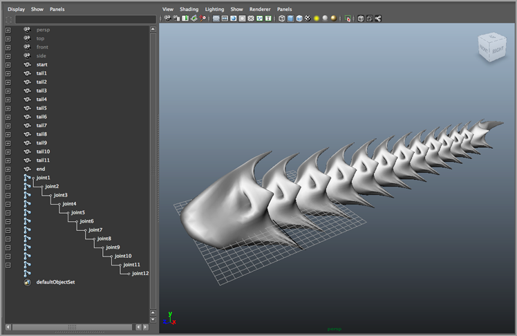
In this example, you’ll use a dynamic curve to control a segmented armored tail. The armored tail consists of polygon pieces, each of which has been parent-constrained to a joint in a chain. The first step is to create a curve (see Figure 15-18).
1. Open the armoredTail_v01.ma scene from the chapter15scenes folder at the book’s web page.
2. Switch to a side view, and turn on Snap To Points.
3. In the viewport’s Show menu, turn off the visibility of polygons so that only the joints are visible.
4. Choose Create ⇒ EP Curve Tool. Click the first joint in the chain on the far left side and the last joint in the chain on the far right side.
5. Press Enter to complete the curve.
The EP Curve tool creates a curve that has four CVs. Using the EP Curve tool is an easy way to create a straight curve. If you want to add more vertices, you can use the Edit Curves ⇒ Rebuild Curve command. In the options, specify how many spans you want to add to the curve. In this example, the curve should work fine with only four CVs.
6. Switch to the perspective view. Turn off the visibility of Joints in the Show menu so that only the curve is visible.
7. Switch to the nDynamics menu set. Select curve1, and choose nHair ⇒ Make Selected Curves Dynamic. In the Outliner, a new hairSystem1 node is created, as are two groups: hairSystem1Follicles and hairSystem1OutputCurves (see
Figure 15-19).
Understanding Dynamic Hair Curve Nodes
The hairSystem1 node controls the dynamics of the curve.
The hairSystem1Follicles group contains the follicle1 node and the original curve1. The follicle node contains settings to control the dynamics of the individual follicles. Some of these settings can override the hairSystem settings. If you selected a number of curves before issuing the Make Selected Curves Dynamic command, the hairSystem1Follicles group would contain a follicle node for each curve. This is explored later on this chapter in the section “Adding Hair to a Character.”
The hairSystem1OutputCurves group creates a duplicate curve named curve2. This curve is a duplicate of the original curve. The output curve is the dynamic curve; the curve in the follicle group is the original, nondynamic curve. The purpose of the nondynamic curve is to serve as an attractor for the dynamic curve if needed. The dynamic curve gets its shape from the follicle curve.
8. Set the timeline to 200, and click the Play button. You’ll see the dynamic curve move a little. (It can be a little hard to see; this will be more obvious in the next step.)
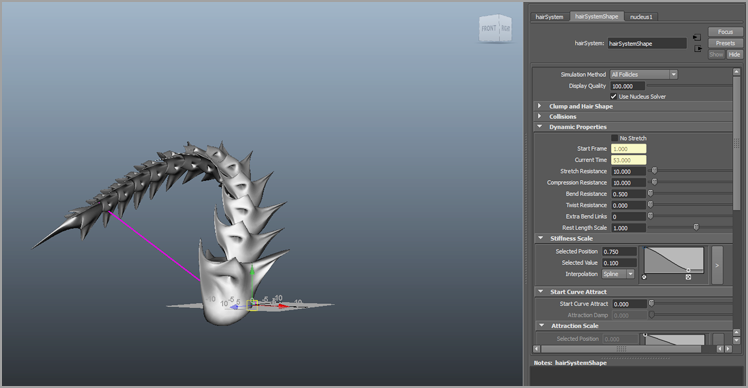
9. Stop the playback, and switch to the hairSystem1 tab.
10. In the Stiffness Scale rollout panel under Dynamics Properties, set the Selected value to 0, and play the scene. You’ll see the dynamic curve droop a little. As the scene is playing, set the Stretch Resistance under the Dynamic Properties rollout to 0.1.
The Stiffness setting controls the rigidity of the curve. A higher Stiffness setting makes the curve less flexible. Lowering the Stiffness value makes the curve bend easily.
As you decrease the Stretch Resistance value, the curve stretches as much as it needs to in order to accommodate the dynamic forces applied to the curve. You’ll notice the curve droop downward, indicating that it has weight. The Nucleus solver controls the gravity, as discussed in Chapter 13, “Introducing nParticles.”
You’ll notice that both ends of the curve appear to be attached to the original curve (see
Figure 15-20).
11. Stop the playback, and rewind the animation.
12. Set Stiffness Scale Selected Value to 1.0 and Bend Resistance to 0.5.
13. Select the follicle1 node in the Outliner, and switch to the Move tool (turn off Snap To Grids or Snap To Points if it is still on).
14. Choose Solvers ⇒ Interactive Playback. The animation starts playing automatically. As it is playing, move the follicle around in the scene; you’ll see the dynamic curve follow the movements.
15. Stop the animation, and switch to the follicleShape1 tab in the Attribute Editor.
16. Set the Point Lock menu to Base. Turn on Interactive Playback, and move the follicle around again. You’ll see that the dynamic curve is attached at only one end.
If you wanted the curve to be attached to the other end, you’d set Point Lock to Tip. To detach the curve entirely, set Point Lock to No Attach.
17. Stop the animation, and rewind the playback.
Keyframe Point Lock
The Point Lock attribute can be keyframed in the Channel Box for the follicle node. To animate a dynamic curve detaching from one end, follow these steps:
1. Set Point Lock to Both Ends.
2. Create a keyframe by right-clicking the Point Lock channel in the Channel Box and choosing Key Selected.
3. Change the current frame on the timeline.
4. Set Point Lock to Tip or Base (the opposite end will become detached).
5. Set another keyframe.
This is a good way to create the effect of a cable or rope snapping.
18. Select the follicle1 node, and set the Translate channels to 0 to return the curve to its start position.
19. With the follicle selected, turn on Snap To Points.
20. Hold the
d key, and use the Move tool to move the pivot point of the follicle to the end of the curve on the side where the dynamic curve is still attached, as shown in
Figure 15-21.
Tips for Moving the Pivot Point
As you move the pivot point, the curve should not move; sometimes it takes a couple of tries to get Maya to switch properly to move pivot mode. An alternative to the d hot key is to press the Insert key on a PC or the Home key on a Mac on the keyboard while the Move tool is activated—not every keyboard has an Insert key, however. Another alternative is while holding d, press w, and then let go of both to lock the move pivot. Repeat the command to unlock the move pivot.
21. When the pivot point is repositioned, Shift+click the Translate and Rotate channels in the Channel Box, right-click, and choose Key Selected from the pop-up menu.
22. Turn on Auto Keyframe; go to various points in the animation, and move and rotate the follicle.
While Auto Keyframe is on, a keyframe is placed on all the Translate and Rotate channels as you make changes to the position of the follicle. The dynamic curve may not update correctly as you make changes; don’t worry about that at the moment.
You want to create an animation where the curve moves around in the scene like a sword slashing through the air.
23. Rewind and play the animation; you’ll see the dynamic curve follow the movements of the follicle as it moves through the air.
24. Save the scene as armoredTail_v02.ma.
To see a version of the scene, open the armoredTail_v02.ma scene from the chapter15scenes folder.
Creating an IK Spline Handle from the Dynamic Curve
In this section, you’ll create an IK spline handle for the armored tail and attach it to the dynamic curve. The dynamics of the curve will be edited to change the behavior of the tail.
1. Continue with the scene from the previous section, or open the armoredTail_v02.ma scene from the chapter15scenes folder.
2. In the perspective view, turn on the visibility of joints in the Show menu.
3. In the Outliner, select and hide the follicle1 node. This prevents you from selecting the wrong curve when creating the IK spline handle.
4. Switch to the Animation menu set, and choose Skeleton ⇒ IK Spline Handle Tool ⇒ Options.
5. In the Tool Settings dialog box, make sure Auto Create Curve and Root On Curve are both off.
6. With the IK Spline Handle tool active, select the first joint in the chain and the last joint in the chain.
7. Zoom in closely, and carefully select the blue curve that runs down the center of the chain.
If the operation is successful, you’ll see the ikHandle1 node appear in the Outliner. The Dynamic curve (curve4) will move out of the hairSystem1OutputCurves group. That should not affect how the curve behaves.
8. Rewind and play the scene. The joints follow the motion of the curves.
9. In the Show menu of the perspective view, turn the visibility of polygons back on and play the scene. The armored tail thrashes around when you play the animation.
10. In the Outliner, select the hairSystem1 node and open its Attribute Editor to the hairSystemShape1 tab.
11. Scroll down and expand the Dynamics section.
The Stiffness Scale edit curve changes the stiffness of the curve along the length of the curve. The left side of the curve corresponds to the stiffness at the base; the right side of the curve corresponds to the stiffness at the tip.
12. Add a point to the Stiffness Scale edit curve by clicking the left side of the curve and dragging downward.
13. Play the animation, and you’ll see the end of the tail lag behind the motion more than the front of the tail. You should be able to edit the curve while the animation is playing and observe the changes (see
Figure 15-22).
14. Save the scene as armoredTail_v03.ma.
The Stiffness setting creates the overall stiffness value for the dynamic curve. Stiffness Scale modifies that value along the length of the curve. Both settings, like almost all of the dynamic curve settings, can be animated.
To see a version of the scene, open the armoredTail_v03.ma file from the chapter15scenes folder.
Using Forces
The settings in the Forces section add levels of control for the curve’s motion. Play the animation in the armoredTail_v03.ma scene, and adjust these settings while the scene loops so that you can see how they affect the motion of the tail.
Mass Affects the motion of the curve only when additional fields (created from the Dynamics menu set) are applied to the curve—for example, a Turbulence or a Drag field. Mass does not change how the curve responds to forces created in the hairSystem1 shape node. Increasing Mass increases the simulated weight of each CV on the curve as the curve moves through a dynamic field.
Drag Creates friction between the dynamic curve and the air. Increasing this value is a good way to simulate the motion of hair in thick fluids.
Tangential Drag Applies a resistance along the direction of the hair curve shape. Increasing this value is also a good way to simulate the motion of hair in thick fluids.
Motion Drag Similar to Drag. However, Motion Drag is affected by the Stiffness Scale attribute. In other words, the Drag setting creates a drag in the motion across the length of the dynamic curve, whereas Motion Drag creates a drag along the length of the curve that is influenced by the Stiffness Scale curve. This setting can be used to fine-tune the motion of the dynamic curve.
Damp Used most often to control erratic motion of dynamic curves. Higher Damp values decrease the momentum of the curve as it follows the motion of the follicle.
Stretch Damp Used most often to control erratic motion of dynamic curves. Higher Damp values decrease the momentum of the curve as it follows the motion of the follicle.
Dynamics Weight Controls the amount of overall influence external dynamic fields (such as Turbulence and Drag) have over the dynamic curve. It does not influence how the Forces settings in the hairSystem node affect the dynamic curve.
Adding Hair to a Character
Hair is created by attaching follicle nodes to a surface. Each follicle node controls a number of hairs. The follicles themselves are styled using a combination of control curves and forces. Follicles and control curves are connected to a hair system node. A single hair system node can control hair connected to any number of surfaces, and a single surface can be attached to multiple hair systems.
When you create hair, you have to consider how you plan to render it. You have the choice of creating Paint Effects strokes for the hair or curves that can be used to render in third-party engines such as Render Man, or creating both Paint Effects strokes and curves. Even though hair uses Paint Effects, it renders using mental ray without the need to convert the hair to polygons.
You can still use Classic Hair, located under nHair ⇒ Classic Hair, to build and style your character’s hair. Once nHair is created, you can toggle between Classic Hair and the Nucleus Solver from within the hair system shape node’s Attribute Editor. In this section, you’ll create and style hair for a character using nHair and the Nucleus framework.
Applying Hair to a Surface
When you want to apply hair to a character, you can either apply the hair uniformly to the entire surface or paint the hair selectively on parts of the surface.
It is common practice to create a nonrendering scalp surface that can be parented to a character’s head and then apply the hair to the scalp surface rather than directly to the character’s head. This allows flexibility because scalp surfaces and their attached hair can easily be swapped between characters. It also speeds up playback in the animation because the hair dynamics are not factored into the calculations required to deform the character’s surface if it has been skinned to a skeleton or to other deformers.
Some animators like to apply separate hair systems to each part of the scalp to control the various sections of a particular hairstyle. For instance, one hair system may be applied to the bangs that hang over the character’s forehead, whereas another system may be used for the hair on the back of the head. In this exercise, you’ll keep things simple by using a single hair system for the character’s hairstyle. Both methods are valid, and as you become comfortable working with hair, you may want to experiment with different techniques to see which approach works best for you.
The following procedure uses the Nancy Hair scene, which contains the rigged nancy character used in Chapter 6, “Animating with Deformers.” The head is rigged to a series of joints. You can select and rotate the headCtrl curves above the head to change the position of the head. A scalp surface has been created by duplicating part of the head geometry. This scalp geometry is parent-constrained to one of the joints in the head rig.
You can apply hair to NURBS or polygon surfaces. When you use polygon surfaces, the UV texture coordinates must be mapped so that none of the UVs overlap and the coordinates fit within the 0 to 1 range in the UV Texture Editor. As with fur, you’ll get better results from your hair system if the UV coordinates have been carefully mapped. Remember to delete history for the surface once you have created UV texture coordinates to keep the coordinates (and attached hair) from moving unpredictably during animation.
1. Open the nancyHair_v01.ma scene from the chapter15scenes folder.
2. In the Outliner, select the scalp surface and open its Attribute Editor.
3. In the scalpShape tab, expand the Render Stats section; then turn off Casts Shadows, Receive Shadows, Motion Blur, and Primary Visibility so that the surface will not render or affect any other geometry in the render.
For the scalp, you’ll create a simple grid and then add follicles if needed later.
Adding Hair to a Surface
You can add hair to a surface in a number of ways. You can paint hair on the surface using the Artisan Brush interface, you can select faces on polygons or surface points on NURBS surfaces and apply hair to the selected components, or you can create a uniform grid of follicles on a surface. Once you attach follicles to a surface, you can add more follicles later to fill in blank areas by painting them on the surface.
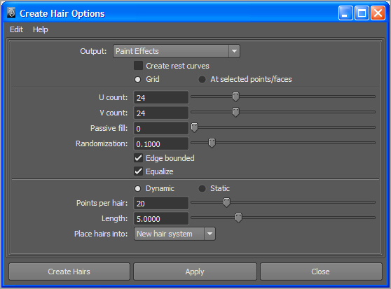
4. Make sure the scalp surface is selected, switch to the nDynamics menu set, and choose nHair ⇒ Create Hair ⇒ Options.
5. In the Create Hair Options dialog box, choose Edit ⇒ Reset Settings to reset the options to the default settings.
6. Set the Output to Paint Effects, and choose the Grid option. Use the following settings:
U and V Count: 24
Passive Fill: 0
Randomization: 0.1
Understanding Follicle Types
Follicles can be dynamic, passive, or static:
Dynamic Follicles Dynamic follicles react to forces and dynamic fields based on the settings in the hairSystem node or on any dynamic overrides created in the follicle shape node. Dynamic follicles can collide with surfaces.
Passive Follicles Passive follicles inherit the dynamic motion of nearby dynamic follicles, which can reduce computational overhead, especially when collisions are involved.
Static Follicles Static follicles have no dynamic motion but can be used to style parts of the hair. You can change the mode of a follicle after creating the hair system if you decide to make a passive follicle dynamic, make a dynamic follicle static, and so on.
The Randomization setting randomizes the arrangement of the grid to make the hair placement look less even.
By increasing the Passive Fill option, a number of the follicles created when the hair is attached to the surface will be passive rather than dynamic. If the Passive Fill option is set to 1, every other row and column of the follicles based on the settings for U and V Count will be passive follicles. If the setting is 2, every two rows and every two columns of follicles will be passive.
When you first create a hair system, you can create a number of passive follicles using this setting. This speeds up the dynamics as you create the initial hairstyle. Later you can convert the follicles to dynamic or static follicles as needed.
7. Turn on the Edge Bounded and Equalize options.
When the Grid method is used, the follicles are placed uniformly on the surface based on the U and V coordinates. If Edge Bounded is on, the follicles are placed up to and including the edge of the UV coordinates. In the case of the example, this means that hairs are placed along the edge of the scalp surface. The Equalize option evens out the spacing of the follicle placement to compensate for areas of the U and V coordinates that may be stretched or squashed.
8. Set Points Per Hair to 20 and Length to 5.
Hairs that have more points per curve are more flexible and have more detail in their motion as they respond to dynamics; they also slow down the playback speed of Maya in the scene. The Length attribute can be modified after creation.
The Place Hairs Into option should be set to New Hair System. If a hair system exists in the scene already, you can use this option to add the newly created hairs into the existing system by selecting it from the list.
Figure 15-23 shows the settings for the new hair.
9. Click Create Hairs to make the hair. The hairs appear as long spikes coming out of the head (see
Figure 15-24).
10. Select the nancy head geometry. Choose nMesh ⇒ Create Passive Collider.
11. Click Play, and the hairs start to fall. After a few moments, the hairs start to settle.
12. Save the scene as nancyHair_v02.ma.
To see a version of the scene, open the nancyHair_v02.ma scene from the chapter15scenes folder.
In the next section, you’ll learn how to style the hair.
Hair Transplants
You can move an existing hair system from one surface to another using the Transplant command. To use this command, follow these steps:
1. Select the hair system you want to move.
2. Ctrl/Command+click the destination surface.
3. From the Dynamics menu set, choose nHair ⇒ Transplant Hair.
If the surfaces have very similar UV texture coordinates, you can choose to move the hair based on the UV coordinates in the Transplant options. Otherwise, you can choose to move the hair based on the closest points in the surface. In this case, make sure that the destination surface is placed and scaled to match the existing hair system and its source.
Determining Hair Shape
A number of settings in the hair system node determine the look of the hair. These are found in the Clump and Hair Shape section of the hair system’s attributes.
1. Continue with your scene or open the nancyHair_v03.ma scene from the chapter15scenes folder.
2. Select hairSystem1, and open its Attribute Editor to the hairSystemShape1 tab.
Display Quality
You can decrease the Display Quality of the nHair to improve performance while working in the scene. Keep in mind, though, this means you will not be viewing the actual amount of hair on the head.
3. The hair appears as groups bunched around long spikes that shoot out from the scalp. Each group of hairs is a clump. The movement of each clump of hair is driven by the movement of the follicles. This way, Maya can create dynamics for thousands of hairs using a much smaller number of follicles. The hair remains as long spikes until you play the simulation and let the hair fall down. For the moment, leave the animation at frame 1. It’s easier to see how the clumps work when the hair is in its spiky state. In the Clump and Hair Shape section, increase the Hairs Per Clump number to 60 to increase the fullness of the hair.
4. Play the animation until frame 20, and then stop the animation.
5. Zoom in to the end of a clump, and move the Bend Follow slider back and forth.
When Bend Follow is at 0, the end of the clump appears flat if the follicle is curved. When Bend Follow is 1, the clump shape is more tubular toward the end of the clump. This attribute should be used to fine-tune the look of your hair as you develop the overall shape.
6. Rewind the animation, and set Clump Width to 0.7. This expands the overall width of the clumps, which helps fill out the hairstyle without the need to add more follicles.
In the Clump and Hair Shape rollout, you can use the following settings to determine the look of the hair:
Baldness Map The Baldness Map field allows you to apply a texture to control where the hair grows on the head. The texture must be a black-and-white 2D texture. The texture itself does not need to be baked as it does with fur. Just like with fur, black areas of the map indicate no hair (or baldness), and white areas indicate places where the hair grows. Texture maps can also be used, much like the texture maps created for fur baldness.
Sub Segments Use this setting to improve the details of the hair (such as curls and kinks) when rendered. Increasing this setting does not affect the dynamics of the hair.
Thinning Higher values decrease the number of hairs per clump to create a thin and wispy look to the hair.
Clump Twist This setting rotates each clump around the base of the follicle. Positive values rotate the clump in one direction; negative values rotate it in the opposite direction. Twisting the clump rotates all of the hairs uniformly. If you like the way the hair looks on one side of the clump, you can use the clump twist to rotate the preferred side toward the camera.
Bend Follow This setting determines how closely the rotation of the clump affects the shape of the hair clumps. This is most noticeable at the end of each clump.
Hair Width Hair Width adjusts the width of the hairs. This setting can be used to thicken or thin the hair. The effect of changing hair width is seen when the hair is rendered. This is a setting you’ll probably want to return to when you are setting up your hair for a render.
Below the Clump and Hair Shape setting sliders are a number of edit curves that can be used to further refine the hair shape. The left side of each curve represents the area of the clump closest to the root; the right side represents the area closest to the tip. Each scale uses the setting in the sliders in the Clump And Hair Shape section as a starting point, so each scale is a modifier for the settings you have already created. The following describes how each ramp affects the look of the hair:
Clump and Hair Width Scale You can exaggerate or reduce the amount of tapering in the clumps by changing the Clump Width Scale edit curve. Hair Width Scale modifies the width of the hairs based on the setting in the Hair Width slider.
Clump Curl The Clump Curledit curve can be used to twist the clumps around the central axis of the follicle. By default, the graph is set so that the value of the curling is at 0.5. By moving a point on the curve up or down (moving up creates values closer to 1; moving down creates values closer to 0), the curling twists in one direction or the other (see
Figure 15-25).
Clump Flatness The Clump Flatness scale can be used to make the clumps appear as flat planks of hair. Higher values along the curve flatten out the clumps. This setting works well for creating the shape of wet hair.
The final two settings in this section are sliders labeled Clump Interpolation and Interpolation Range:
Clump Interpolation Increasing the Clump Interpolation slider spreads the hair out between clumps. This slider can be used to even out the shape of the hair so that the clumping is much less obvious. Dynamics are calculated based on the position of each clump. If you set a high Clump Interpolation value, you may find that hairs do not appear to collide correctly. This is because the interpolation can push hairs outside the boundary of the original clump width, and thus their placement exceeds the collision width of their clump.
Interpolation Range Interpolation Range sets the limits for how far a hair can move out of the width of the clump when Clump Interpolation is increased. The value set in Interpolation Range is multiplied against the Clump Width setting.
7. Play the animation to frame 50 and stop.
8. Remove any extra points you may have placed on the Clump Width Scale and Clump Curl so that there are only two points on the scales, one on the far right and one on the far left.
9. Set the value of the point on the left side of the Clump Width Scale to 1; set the point on the far right to 0.32.
10. Set the point on the far right of the Clump Curl curve to 0.6.
11. Set the point on the far left of the Clump Flatness scale to 0.5. Add a point to the far right side of Clump Flatness, and move it to 0.7. This helps the roots of the hair to lie closer to the head, creating less of a “poufy” shape.
12. Set Clump Interpolation to 0.3. Leave Interpolation Range set to the default value of 8.
13. Rewind and play the animation, and make any changes you’d like to the shape of the hair. The length, color, and other properties are further defined in the next section. Rewind and play the animation (see
Figure 15-26).
14. Save the scene as nancyHair_v03.ma.
To see a version of the scene, open the nancyHair_v03.ma scene from the chapter15/scenes folder.
Follicle Overrides
Many of the settings found in the hairSystemShape node are also found on the nodes for individual follicles in the Per Follicle Overrides section of each follicle’s Attribute Editor. You can use these overrides to refine the hair shape for individual follicles. Dynamic overrides are available only for dynamic follicles; these settings are grayed out for passive or static follicles.
Styling Hair
Once the hair has been set up, you can use a number of tools to style the hair. You can use dynamic fields as a hair-styling tool, paint follicle properties on the hair, or even manipulate the CVs of control curves.
Start and Rest Positions
Before styling the hair properly, you should create a start position for the hair, so that the animation does not start with the hair sticking straight out of the head. Doing so makes styling much easier.
The start position represents the shape of the hair at the start of the simulation. The rest position represents the hair’s shape when no forces are acting upon it. These are very similar, but you can distinguish between the two by thinking of it like this: imagine an animation where a character is jumping up and down and then stops. The animation starts with the character in midair. You want to set the start position to represent what the hair looks like when the character is in midair. Once the character stops jumping and the hair settles, the hair assumes its rest position. For some animations the start and rest positions may look exactly the same; at other times, such as in the example described, the start and rest positions look different.
1. Continue using the scene from the previous section, or open the nancyHair_v03.ma scene from the chapter15scenes folder.
2. Play the animation until the hair has completely settled.
3. Once the hair has settled, expand the hairSystem1Follicles group in the Outliner and Shift+click all of the follicle nodes.
4. Choose nHair ⇒ Set Start Position ⇒ From Current.
5. Set the rest position by choosing nHair ⇒ Set Rest Position ⇒ From Current.
6. Rewind the animation. The hair should now be down and relatively motionless at the start of the animation.
The start and rest positions are determined by two sets of curves that drive the follicles. You can activate the visibility of these curves in the Perspective window.
7. In the Viewport menu, use the Show menu to turn off the visibility of Strokes. This hides the Paint Effects hair.
Hairstyle Presets
Maya comes with a number of preset hairstyles in the Visor, as shown here. You can open these by choosing (from the nDynamics menu set) nHair ⇒ Get Hair Example. To use a hairstyle, right-click one of the icons and choose to import the file into your scene. Each preset style comes with hairline geometry that can be parented to your character’s head. Or you can copy the style using the Transplant Hair option.
Setting the Start and Rest Positions
Notice that you can set the start position from the rest position, and vice versa. You can change these positions at any time as you continue to work on the hair and any animations. Notice also that the start and rest positions are applied to the follicles themselves, rather than to the hair system. This means that you can set start and rest positions for individual follicles if needed.
8. Select the hairSystem1 node, and choose nHair ⇒ Display ⇒ Start Position. A series of curves appears in blue, representing the hair’s start position.
9. Choose nHair ⇒ Display ⇒ Rest Position. The rest position curves appear in red. If the start and rest positions for the hair system are different, each set of curves will have a different shape.
10. Choose nHair ⇒ Display ⇒ Start Position. Save the scene as nancyHair_v04.ma.
To see a version of the scene, open the nancyHair_v04.ma scene from the chapter15scenes folder at the book’s web page.
Painting Follicle Attributes
Using the Artisan Brush interface, you can paint follicle attributes. Before doing this, you must make sure that the hair is in its rest or start position. Some attributes, such as Inclination, require that the animation be on frame1.
1. Continue with the scene from the previous section, or open the nancyHair_v04.ma scene from the chapter15scenes folder.
2. Select the hairSystem1 node or the scalp surface.
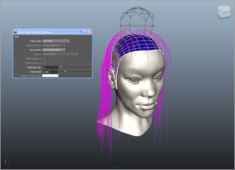
3. From the nDynamics menu set, choose nHair ⇒ Paint Hair Follicles.
The Tool Options area for the Artisan Brush interface opens as well as the Paint Hair Follicles Settings pop-up box.
4. Set Paint Mode to Trim Hairs. This setting allows you to reduce the length of the hair as you paint across the follicles.
For the dynamics to remain consistent, you must adjust the number of points on the hair as you paint. When you created the hair originally, the Points Per Hair attribute was set to 10, so to trim the length of a hair by half, set Points Per Hair to 5. The Points Per Hair setting determines how the hair will be trimmed. When you set Points Per Hair to 5, the hair will be trimmed to half the original length regardless of the Hair Length setting.
5. Set Points Per Hair to
5, and paint across the follicles in the front of the scalp to create bangs for the nancy character (see
Figure 15-27).
6. Once you have trimmed the hair, select the follicles in the Outliner (it’s easiest just to Shift+click all the follicles rather than figure out which ones were painted), and choose Hair ⇒ Set Rest Position ⇒ From Current.
7. To extend the hair, set Paint Mode to Extend Hairs, and increase Points Per Hair to a number larger than 10. Remember to reset the rest and start positions after extending the hair.
You can use the nHair ⇒ Scale Hair tool to apply global scaling to the hair. To use this tool, select it from the nHair menu, and drag left or right. This tool will scale all aspects of the hair, so some adjustment to the shape and dynamics settings may be required after using the tool.
Quick Select Follicles
Repeatedly selecting all the follicles or certain follicles whenever you need to set the rest or start position gets tedious rather quickly. You can speed up the process by creating a quick selection set for the follicles.
1. Shift+click the follicles in the Outliner.
2. Choose Create ⇒ Sets ⇒ Quick Select Set.
3. Name the set NancyFolliclesAll.
4. You have the option to create a shelf button for this set. To do this, click Add Shelf Button.
The button appears in the shelf. Every time you need to select all the follicles, just click the button.
5. If you want the button to appear on the shelf the next time you start Maya, click the downward-facing black triangle next to the shelf, and choose Shelf ⇒ Save All Shelves.
Be aware that this selection set is specific to this scene. If you click the button in another scene, you will get an error.
If you want to take it a step further, try writing a MEL script that selects the follicles and sets the rest and/or start position all in one click. Creating MEL scripts is discussed in Bonus Chapter 1, “Scripting with MEL and Python,” on this book’s web page.
To paint other attributes, set Paint Mode to Edit Follicle Attributes and choose an attribute from the Follicle Attribute menu. When painting these attributes, the Value setting in the Brush Options area determines the value painted on the follicles.
8. Save the scene as nancyHair_v05.ma.
To see a version of the scene, open the nancyHair_v05.ma scene from the chapter15scenes folder.
Modifying Curves
You can modify curves directly by moving their CVs or by using the tools in the Hair ⇒ Modify Curves menu. By modifying curves directly, you can fine-tune a style.
You can modify only start or rest curves. To do this, use the Show menu in the viewport window to disable the visibility of strokes in the scene, and choose nHair ⇒ Display Rest Position (or Start Position). Select the curve (or right-click the curve, and choose Control Vertex to work just on selected CVs), and apply one of the actions listed in the nHair ⇒ Modify Curves menu. You can also edit the shape of the curve directly using the Move tool to change the position of CVs on the curve (see Figure 15-28).
As you are editing the curve, you can lock the length so that the changes you make do not stretch the curve beyond its original length. Select the curve, and choose nHair ⇒ Lock Length (or use the l hot key). Conversely, you can unlock the curve if you want to change its length.
Curling, Noise, Sub Clumping, and Braids
Curling, Noise, and Braids all work best when the Sub Segments attribute in the Clump and Hair Shape section of the hair system node is increased. You can find the Curling and Noise settings in the Displacement section of the hair system node.
The Sub Clumping setting causes the hair within clumps to bunch together. This helps when you are creating wet or kinky hair.
The Braid option is available as an attribute for individual hair follicle nodes. For a braid to work successfully, you may need to alter the clump shape and the hairs per clump. It may be a good idea to use a separate hair system to create a detailed braid.
Note
If Maya 2014 allows you to delete specific parts of your hair system. This works for hair curves and Paint Effects hair. Deleting nHair is useful if you wish to retain hair curves or the hair system nodes in order to reuse them in other hair simulations. Select the curves you want to delete and choose nHair ⇒ Delete Hair..
Rendering Hair
Rendering hair can be done using Maya Software or mental ray. The hair should be either Paint Effects strokes or Paint Effects strokes converted to geometry. Paint Effects strokes are discussed in detail in Chapter 8, “Paint Effects.”
Coloring Hair
If you decide to render hair as Paint Effects strokes, you can change the Hair Color, Translucence, and Specular properties using the settings in the hairSystemShape tab’s Shading section.
Rendering hair is a straightforward process. If you’re not familiar with Paint Effects, you should review Chapter 8 before reading this section.
When you convert hair to geometry, the Hair Tube shader is automatically applied. You can render Paint Effects hair using mental ray without the need to convert the hair to geometry.
When you are ready to render the hair, you’ll want to increase the Hair Sub Segments setting in the hairSystem node's Attribute Editor, as well as Hairs Per Clump, Hair Width, and Hair Width Scale, in order to create fuller hair. You can always add follicles as well using the Paint Follicles tool.
In the Render Stats section of the hairSystem node, you can enable Receive Shadows, Visible In Reflections, and Visible In Refractions when rendering with mental ray. On the Quality tab of the mental ray render settings, you can use the Rapid Motion Hair preset to render hair without raytracing or the Production: Fine Trace preset for rendering with raytracing. If the hair will not render using mental ray, make sure the Render Fur/Hair setting is activated on the Features tab of the mental ray Rendering section.
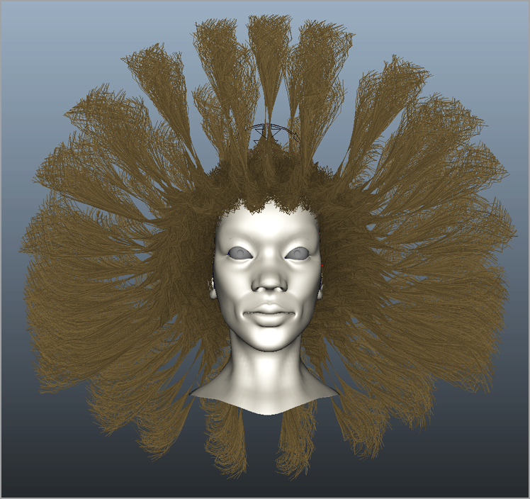
In this scene, the dreads.mel preset, found on the Hair Examples tab of the Visor, is applied to the nancy model. The hairLights.mel file has also been imported from the Visor and applied to the scene.
1. Open the renderHair.ma scene from the chapter15scenes folder at the book’s web page.
2. Switch to the quarterSide camera, and create a test render in the Render View window.
The scene is set up to render using mental ray. The render will take a couple of minutes. Figure 15-29 shows the results (shadows have been enabled for the lights in the image).
Most standard lights will render hair nicely. When you’re testing the look of the hair, using the hairLights.mel preset makes it easy to see how the hair will look when rendered.
Creating Clothing for Characters
In this section, you’ll explore techniques for using nCloth to add dynamic motion to a character’s clothes. The example files are simple, but you can use the same techniques for more complex characters and models.
The Nucleus solver divides its computations into multiple threads for self-colliding surfaces and stretch resistance. Additional threading is also used to speed up playback of simulations with multiple nCloth objects on the same solver. Before starting this section, you should review Chapter 13 (“Introducing nParticles”) and Chapter 14 (“Dynamic Effects”) so that you understand how nDynamics and the Nucleus solver work.
Modeling Clothes for nCloth
The models you create for use with nCloth must be polygon meshes. Beyond that, there is nothing special about how you model your clothing. Smooth mesh polygons work just as well as standard polygons. You’ll start by taking a look at an example scene.
This scene has a simple cartoon character that has been rigged and animated. The character has a shirt and pants that have been created using standard polygon modeling techniques. Both objects are currently smooth mesh polygons. The scene has been arranged so that the display layers contain the major components of the model and the animation rig.
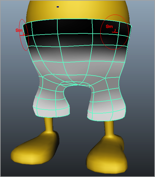
1. Open the
simpleMan_v01.ma scene from the
chapter15scenes folder at the book’s web page (see
Figure 15-30).
2. Switch to the nDynamics menu set.
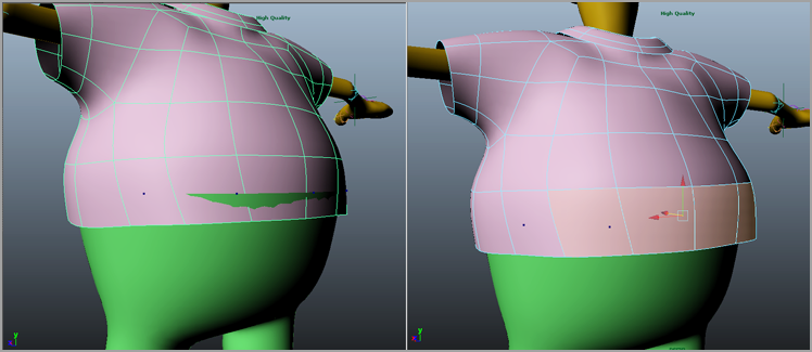
3. Select the pants, and choose nMesh ⇒ Create nCloth. The pants switch to standard polygon mode.
4. Select the pants, and press the 3 key to switch to smooth mesh polygons.
5. Play the scene. You’ll see the pants fall down. (This kind of thing can be embarrassing, but it happens a lot to cartoon characters; see
Figure 15-31.)
The first step in preventing the pants from falling is to make the character’s body a Passive Collider object. It does not matter that the character is already rigged and animated. However, it’s a good idea to convert the polygons to nCloth objects (both nCloth and Passive Collider objects) when the character is in the default pose and there are no intersections between the nCloth and Passive Collider geometry.
1. Rewind the animation.
2. In the Display Layer Editor, click the R next to the MAN layer to turn off Reference mode so that you can directly select the man geometry.
3. Select the man geometry, and choose nMesh ⇒ Create Passive Collider.
Simple vs. Complex Geometry
The geometry used for the man is fairly simple. If you have a complex character, you may want to use a lower-resolution copy of the geometry as a collision object. This lower-resolution copy should have its Primary Visibility setting turned off in the Render Stats section of its Attribute Editor, and the geometry should be skinned to joints or deformers in a way that matches the deformations of the higher-resolution objects.
4. Make sure that you are starting at frame 0 and play the scene. The pants still fall down, but the character’s feet stop them from falling indefinitely.
5. Save the scene as simpleMan_v02.ma.
To see a version of the scene, open the simpleMan_v02.ma scene from the chapter15scenes folder.
In the next section, you’ll create a constraint that will keep a character’s pants from falling down.
Using Constraints
The simplest way to keep the character’s pants on is to create a transform constraint. A transform constraint attaches the selected vertices on an nCloth object to the pivot point of another object without affecting the position of the nCloth vertices. When the constraining object is translated or rotated, the vertices follow along, dragging the rest of the nCloth object with them.
1. Continue with the scene from the previous section, or open the simpleMan_v02.ma scene from the chapter15scenes folder at the book’s web page.
2. Turn off the visibility of the MAN layer, and turn on the visibility of the JOINTS layer.
At the center of the pelvis, you’ll see a locator. This is the rootControl locator used to animate the character’s skeleton. You can use this locator as the constraining object for the nCloth pants.
3. Right-click the pants, and choose Edge to switch to edge selection mode.
4. Double-click one of the edges at the top of the pants. Doing so selects all the edges that run around the top of the pants (left image,
Figure 15-32).
5. Hold the mouse over the selected edges, press the Ctrl/Command key, and RMB-drag to the left.
6. Select the To Vertices label from the marking menu. This converts the selection to vertices (center image,
Figure 15-32).
7. With the vertices selected (they should be highlighted in yellow) in the Outliner, Ctrl/Command+click the rootCtrl locator, and choose nConstraint ⇒ Transform. The vertices should turn green, indicating that they are constrained. In the Outliner, you’ll see a new dynamicConstraint1 node has been created.
8. Turn the visibility of the MAN layer back on, and play the animation. The pants should now stay in place, and when the man starts moving, they should collide with the character’s legs (right image,
Figure 15-32).
9. Save the scene as simpleMan_v03.ma.
To see a version of the scene, open the simpleMan_v03.ma scene from the chapter15scenes folder at the book’s web page.
You can also constrain objects to components of nCloth objects, such as vertices. Using this technique, you can easily simulate the effect of buttons holding a shirt together.
1. Continue with the scene from the previous section, or open the simpleMan_v03.ma scene from the chapter15scenes folder.
2. In the Display Layer Editor, turn on the visibility of the SHIRT layer.
3. Before converting the shirt to an nCloth object, make sure that it does not intersect with the pants. Rotate the view so that you can see the back of the character; here you can see that the shirt is intersecting the pants (left image,
Figure 15-33).
4. Right-click the faces near the intersection, and choose Faces.
5. Use the Move tool to move the faces outward just enough that they do not intersect the pants (right image,
Figure 15-33).
6. Select the shirt, and choose nMesh ⇒ Create nCloth. The shirt switches back to standard polygon mode; select the shirt, and press the 3 key to return to smooth mesh.
7. Rewind and play the animation. The shirt falls until it collides with the character geometry. It moves as the character moves; however, you can see the front of the shirt fly open (see
Figure 15-34).
8. Zoom in to the front of the shirt, and turn off the visibility of the MAN and PANTS display layers.
9. Right-click the shirt, and choose Vertex.
10. Switch to wireframe mode. Select the two vertices at the top of the shirt close to the collar (see
Figure 15-35, left image).
11. Choose nConstraints ⇒ Component To Component. This creates a constraint between the two vertices.
12. Repeat steps 10 and 11 to create constraints for the other three pairs of vertices running down the shirt. You don’t need to constrain the two at the very bottom. You should end up with four constraints running down the front of the shirt (see
Figure 15-35, right image).
13. Switch to shaded mode, turn on the MAN and PANTS layers, and rewind and play the scene. The front of the shirt is now bound as if it has buttons (see
Figure 15-36).
14. Save the scene as simpleMan_v04.ma.
To see a version of the scene, open the simpleMan_v04.ma scene from the chapter15scenes folder at the book’s web page.
nConstraint Membership
You can add, replace, or remove vertices from an nConstraint interactively using the nConstraint Membership Tool. You can also manually select the vertices and select the specific tool from the nConstraint drop-down menu.
Maya 2014 adds a new type of constraint called simply Component. The Component constraint differs from the Component To Component constraint you just used; you can use it to replace nCloth’s internal Stretch constraints. As a result, you gain a high level of individual control. The following steps demonstrate the process and the potential for the Component constraint.
1. Continue with the scene from the previous section, or open the simpleMan_v04.ma scene from the chapter15scenes folder.
2. Select all of the vertices of the man’s shirt except for his sleeves (see
Figure 15-37).
3. Open the tool options for nConstraint ⇒ Component. Make sure you are using the defaults by resetting the tool. Choose Apply to add the constraint (see
Figure 15-38).
Single Edge
The Single Edge parameter lets you specify how the edges receive the constraint. Leaving the setting at its default of 0 causes all of the edges to have a constraint. A value of 1 adds the constraint to the edges in only one direction, while 2 adds them orthogonally to the first row of constraining edges. Adding the constraint in this manner gives you individual control over each of the surface’s directions. By decreasing the Rest Length Scale parameter on the constraint itself, you can cause sleeves to roll up or stretch independently with gravity.
4. The Component constraint now controls the stretch values of the edges. Open the nCloth’s Attribute Editor. Set the Stretch Resistance value to 0.0.
Press the play button to see the effects. The shirt holds together well where the constraint was added, but the sleeves slink down with gravity since they have no stretch resistance (see
Figure 15-39).
5. Return to frame 1. Select the two end loops of vertices from each sleeve and choose nConstraint ⇒ Component. The same options from step 3 are applied.
6. Press the play button to see the effects of the two constraints. Compare these to how the simulation worked without them. The sleeves are allowed to stretch more since there are no cross links holding back the garment’s ability to stretch. There is no need to save the scene file to continue.
Connecting Buttons to the Shirt
You can connect buttons to the shirt geometry using the Point On Poly constraint:
1. Continue with the scene from the previous section, or open the simpleMan_v04.ma scene from the chapter15scenes folder at the book’s web page.
2. In the Outliner, select button1. The button is located at the origin, so currently it is in the center of the character. Use the Move tool to move the button close to the top of the shirt. Enter the following settings:
Translate X: 0.115
Translate Y: 3.576
Translate Z: 2.295
3. Right-click the shirt geometry, and choose Vertex to switch to vertex selection mode.
4. Select one of the vertices toward the top of the shirt on the inside edge (see
Figure 15-40). Shift+click the button1 node.
5. Switch to the Animation menu set, and choose Constrain ⇒ Point On Poly. The button will snap to the geometry. Most likely, the position and the rotation will be off.
6. In the Outliner, select the button1 object, expand it, and select the button1_pointOnPolyConstraint1 node.
7. Open the Channel Box, and MMB-drag the field for Offset Rotate X to rotate the button to a better position; try a value of
75. You can use the other Offset fields to fine-tune the rotation and position of the button (see
Figure 15-41).
8. Repeat the process to constrain the other three buttons in the Outliner to the shirt.
9. Save the scene as simpleMan_v05.ma.
To see a version of the scene, open the simpleMan_v05.ma scene from the chapter15scenes folder at the book’s web page.
You can also select a face of a polygon object and use the Point On Poly constraint to attach an object to a polygon face.
Applying Forces
You can use wind or a directional force to move an nCloth object. You can assign these locally, affecting the object and leaving all other nCloth objects unaffected. This feature can be useful to give elements such as capes a cinematic feel. The settings to modify a local force or local wind are located on the nCloth shape node (see Figure 15-42).
Painting nCloth Properties
nCloth properties can be painted to gain detail in your simulation. You can paint properties such as Bounce, Stretch, and Wrinkle onto an nCloth object. All the properties can be painted as vertex maps or texture maps.
When you paint a vertex property map, you paint property values directly onto the vertices of the object, similar to painting smooth skin weights for joints. The more vertices you have in your object, the more detail you can create for your vertex property map. The vertex map values are saved with the object, so you do not need to link to external map files.
Texture property maps are independent of the number of vertices in the object, but they do require that UVs are properly created for the object, meaning that the UVs do not overlap and do remain within the 0 to 1 range in the UV Texture Editor. Texture property maps for nCloth objects are similar to texture property maps created for fur. However, you do not need to bake the maps after applying them.
When you paint a vertex or texture map, the map is listed in the Attribute field in the Dynamic Properties section of the nCloth shape node’s Attribute Editor.
In this example, you’ll paint Wrinkle attributes for the simple man character’s pants. A wrinkle map displaces an nCloth object to create folds in the surface. You can paint detailed wrinkles into objects with a lot of vertices. In this example, you’ll use the wrinkle map to add cartoonish embellishments to the pants, which have a fairly low number of vertices.
When applying a Wrinkle attribute, positive values push the nCloth outward, while negative values push it inward. There are a few peculiarities about painting Wrinkle values, which you’ll explore in this exercise:
1. Continue with the scene from the previous section, or open the simpleMan_v05.ma scene from the chapter15scenes folder.
2. Turn off the visibility of the SHIRT and JOINTS layers.
3. Rewind and play the animation. The pants maintain their shape until they start to collide.
4. Rewind the animation again; select the pants object, and choose (from the nDynamics menu set) nMesh ⇒ Paint Vertex Properties ⇒ Wrinkle ⇒ Options.
The pants turn white, indicating that a value of 1 is applied to the vertices of the pants for the Wrinkle property. Make sure the Renderer in the Viewport menu is set to Default Render Quality so that you can see the color values painted onto the pants geometry.
5. Rewind and play the animation. The pants suddenly bloat outward even though you have not made any changes (see the top image in
Figure 15-43). What just happened?
When you start to create the wrinkle map, Maya applies a value of 1 to all the vertices of the object at the moment the map is created. Prior to creating the wrinkle map, no Wrinkle value is applied to the pants, so they do not bloat outward until the map is made. This behavior is specific to the wrinkle map.
6. In the Tool Settings dialog box, set the value to 0. Make sure that the Paint Attributes menu in the nCloth Attributes rollout panel of the Tool settings is set to Wrinkle.
7. Click the Flood button, and rewind the animation.
The pants turn black, and the bloating disappears. The wrinkle values are now set to 0 for all the vertices of the pants geometry (see bottom image in
Figure 15-43).
At this point, you’ll paint the area where the pant legs emerge from the pants with a value of –0.2 so that the pant legs shrink inward. Notice, however, that the Value slider in the Artisan Tool options goes only from 0 to 1.
8. In the Tool Settings dialog box, look at the Min/Max value fields. Set the first field, which is the Min Value, to -1, and the second field, which is the Max Value, to 1.
Now it is possible to paint negative numbers, but you’ll notice that since the black color on the pants indicates a value of 0, there is no color feedback for negative numbers. This can be changed as well.
9. Scroll down to the bottom of the Tool Settings dialog box, and expand the Display rollout panel. Make sure Color Feedback is on. Set Min Color to
-1 and Max Color to
1(see
Figure 15-44).
The pants turn gray, indicating that the current value applied to the vertices (0) is in the middle range of colors between black and white. As you paint negative values on the pants, you’ll see darker areas appear.
10. Set the Value slider to -0.2, and paint around the area where the pant legs meet the pants.
11. Rewind and play the scene. You’ll see the tops of the pant legs shrink in a little.
12. To create flares (flares on shorts are apparently all the rage now), set the value to
0.4, and paint the cuffs of the pants (see
Figure 15-45).
13. To create the impression of a drawstring, paint a value of -1 around the area of the pants where a belt would go.
14. Press the q hot key to switch to the Select tool. Doing so will close the Artisan tool; the pants return to green.
15. Rewind and play the animation. Experiment making more changes by painting various Wrinkle values on the pants.
16. Save the scene as simpleMan_v06.ma.
To see a version of the scene, open the simpleMan_v06.ma scene from the chapter15scenes folder.
To learn more about fur, hair, and nCloth, check out Maya Studio Projects: Photorealistic Characters (Sybex, 2011).
The Bottom Line
Add fur to characters Maya Fur is a rendering module that adds realistic short hairs to the surface of characters to simulate fur. Fur can be rendered using both Maya Software and mental ray. The placement, length, and other attributes of fur can be controlled by painting on the surface with the Artisan tool interface. When adding fur to polygons, the success of the fur is largely dependent on how well the UV texture coordinates have been mapped.
Master It Create furry whiskers for the giraffe model used in Chapter 11.
Add dynamic motion to fur By using hair curves as a control, you can make fur react to dynamic forces.
Master It Create a field of grass that blows in the wind.
Create dynamic curves A standard Maya curve can be made dynamic by using the Make Dynamic Curves action in the Hair menu. A copy of the curve is created that will respond to dynamic motion and forces. The curve can be used in skeletons for IK Spline tools, as a source for Paint Effects strokes, as a modeling tool, or for any other effect that requires curves.
Master It Create a flag using dynamic curves.
Add hair to characters Hair is created using Paint Effects strokes that are controlled by follicles. The follicles are dynamic curves that respond to forces and movement. Follicles can be applied to polygon or NURBS surfaces as a grid or by painting on the surface. The Visor contains a number of hair presets that can be imported into a scene.
Master It Add hair to the top of the giraffe’s head from Chapter 11.
Style hair Hair can be styled by painting attribute values on follicles, or by directly editing the CVs of start or rest curves.
Master It Create an avant-garde hairdo for the nancy character by painting attributes.
Use hair constraints Hair constraints can be used to control the motion of hair or to connect the hair to props, such as hair ties and scrunchies.
Master It Use a constraint to create a ponytail for a character.
Paint nCloth properties Properties such as Bounce, Stretch, and Wrinkle can be painted onto nCloth objects using either texture or vertex painting techniques. When painting properties, the Min and Max Value ranges in the Artisan interface may need to be altered to allow for values beyond the range of 0 to 1. Vertex maps have the advantage that the values are not stored in an external texture file.
Master It Add starch to the simple man’s shirt by painting a Rigidity value on the shirt geometry.