
Chapter 16
Scene Management and Virtual Filmmaking
More and more computer-generated movies are being made. Every aspect of the production is created within the 3D world. This can be hundreds to even thousands of objects in a single scene. Often, multiple artists build these objects. The Autodesk® Maya® software allows you to tackle large scenes and complex objects with a special set of tools, and it makes it easy to work within a team.
When all of the assets are built, it’s time to film. As with all filmmaking, the story is told through the camera. The camera is used to manipulate the elements of the scene, letting viewers know on what they need to focus and how they should feel about what is going on in the scene.
Although the technical aspects of using the cameras are not difficult to learn, mastering the art of virtual cinematography can take years of practice.
In this chapter, you will learn to
- Use assets
- Create file references
- Determine the camera’s image size and film speed
- Create and animate cameras
- Create custom camera rigs
- Use depth of field and motion blur
- Create orthographic and stereo cameras
- Use the Camera Sequencer
Organizing Complex Node Structures with Assets
A production pipeline consists of a number of artists with specialized tasks. Modelers, riggers, animators, lighters, technical directors (TDs), and many others work together to create an animation from a director’s vision. Organizing a complex animation sequence from all of the nodes in a scene can be a daunting task. Assets (collections of nodes that you choose to group together for the purpose of organization) are designed to help a director separate the nodes in a scene and their many attributes into discrete interfaces so that each team of specialized artists can concern itself only with its individual part of the project.
An asset is not the same as a group node; assets do not have an associated transform node and do not appear in the viewport of a scene. For example, a model, its animation controls, and its shaders can all be placed in a single asset. This example demonstrates some of the ways that you can create and work with assets.
Creating an Asset
In this example, you’ll create an asset for the front wheels of a vehicle:
- Open the
vehicle_v01.mafile from thechapter16scenesdirectory at the book’s web page (www.sybex.com/go/masteringmaya2016). You’ll see a three-wheeled vehicle. In the Outliner, the vehicle is grouped. - Expand the vehicle group in the Outliner. The group consists of subgroups for the two front wheels, the rear wheel, the chassis, the suspension, and a NURBS curve named steering.
-
Select the steering node in the Outliner. This is the animation control for the steering. Switch to the Rotate tool. Rotate the steering node on the y-axis. The front wheels match the arrow’s orientation (see the left image in Figure 16.1).
If you select one of the front_wheel groups in the Outliner, you’ll see that its Rotate Y channel is colored yellow in the Channel Box, indicating it has an incoming connection. The steering curve’s Y rotation is connected to both front_wheel groups’ Y connection.
- Select steering again, and switch to the Move tool.
-
Move steering up and down along the y-axis. The front wheels rotate on the x-axis based on the height of the steering object, making them tilt (see the right image in Figure 16.1).
If you look in the Channel Box for either of the front_wheel groups, you’ll see that the Rotate X channel is colored orange, indicating that it has been keyframed. The Rotate channels of the group are using a driven key to determine their values. The keyframe’s driver is the Y translation of the arrow group.
- Select the vehicle group node.
-
Drag the red arrow of the Move tool to translate the vehicle back and forth along the x-axis. All three wheels rotate as the car moves.
If you expand the front_wheel1 group in the Outliner and select the wheel1Rotate child group node, you’ll see that the Rotate Z channel is colored purple in the Channel Box, indicating that an expression is controlling its z-axis rotation. You can open the Attribute Editor for the front_wheel1 group and switch to the expression4 tab to see the expression, as shown in Figure 16.2. (The field isn’t large enough to display the entire expression; you can click the field and drag left or right to read the whole expression.)
This model uses a simple rig, but already there are a lot of nodes connected to the vehicle geometry to help the job of the animator. To simplify, you can create an asset for just the wheels and their connected nodes so that the animator can focus on just this part of the model to do their job without having to hunt through all of the different nodes grouped in the Outliner.
- In the Outliner, expand the vehicle group and the two front_wheel groups.
- Ctrl/Cmd+click front_wheel1, wheel1Rotate, front_wheel2, wheel2Rotate, and the steering curve node.
- Open the Hypergraph in Connections mode (Windows ➣ Hypergraph: Connections) (see Figure 16.3).
- In the Hypergraph, select the node named time1 and the vehicle node, and drag them out of the way of the other nodes.
- Drag a selection over all of the nodes except time1 and vehicle. These nodes include the group nodes, keyframe nodes, and expression nodes, all related to controlling the rotation of the front_wheel groups.
- In the Hypergraph menu, choose Edit ➣ Asset ➣ Advanced Assets ➣ Create ➣ ❒. (Options is selected by clicking the small square to the right of the command list in the menu.)
- In the Create Advanced Assets Options dialog box, type front_wheels in the Name field. Make sure that all of the settings under Include Options and Publish Options are deselected (see Figure 16.4). All of the keyframes and expressions are applied to the rotation of the wheel groups, not the geometry nodes contained in the groups, so you needn’t worry about including the contents of the groups in the asset.
- Choose the Create Asset option at the top of the dialog box.
-
Click Apply And Close to create the asset.
In the Hypergraph, you’ll see a gray box labeled front_wheels; this box is also visible in the Outliner. The time1 and vehicle nodes are still visible in the Hypergraph. It may appear as though they have been disconnected, but that’s not actually the case.
- Select the front_wheels asset in the Hypergraph, and graph its input and output connections (Graph ➣ Input And Output Connections). The connections to the time1 and vehicle nodes are visible again.
- Select the front_wheels asset in the Hypergraph, and click the Expand Selected Assets icon on the Hypergraph toolbar (or double-click the container). You will see the nodes within the container (see Figure 16.5).
-
Double-click the thick border of the asset to collapse it, or click the Collapse Selected Assets icon at the top of the Hypergraph.
You can select a node inside the container and remove it from the container by right-clicking the node and choosing Remove From Container. In addition, you can resize the container by moving nodes against the containers borders.
- Save the scene as
vehicle_v02.ma.

Figure 16.1 The Y rotation of each front wheel is connected to the Y rotation of the steering control (left). The X rotation of each front wheel is connected to the Y translate of the steering control, giving the animator the ability to tilt the wheels if needed (right).

Figure 16.2 The Z rotation of the wheels is controlled by an expression node. The expression node is a separate tab in the Attribute Editor.

Figure 16.3 The vehicle group is expanded, and several of the nodes related to the front wheels are selected and graphed on the Hypergraph.

Figure 16.4 The options are set for the container that will hold all of the selected nodes in the Hypergraph.

Figure 16.5 Expanding the view of a container in the Hypergraph makes the connections between nodes within the container visible.
Publishing Asset Attributes
You can publish selected attributes of the container’s nodes to the top level of the container. This means that the animator can select the asset node and have all of the custom controls available in the Channel Box without having to hunt around the various nodes in the network. You can also template your asset for use with similar animation rigs.
In this exercise, you’ll publish the attributes of the front_steering asset:
- Continue with the file from the previous section, or open
vehicle_v02.mafrom thechapter16scenesfolder at the book’s web page. - In the Outliner, select the front_wheels asset and expand the node by clicking the plus sign to the left of the node. Select the steering node from within the asset.
- In the Channel Box, select the Translate Y channel and, from the Edit menu in the Channel Box, choose Publish To Asset ➣ ❒.
- In the Publish Attribute Options dialog box, choose both Selected Channel Box Attributes and Custom Name.
- Type wheelTilt in the Custom String field. Click Apply, and then click Close (see Figure 16.6).
- Select the front_wheels asset in the Outliner; you’ll see the wheelTilt channel has been added in the Channel Box. If you change this value between –1 and 1, the arrow controller moves up and down and the front wheels tilt.

Figure 16.6 The Translate Y attribute of the steering node is published to the container under the name wheelTilt.
Using the Asset Editor
The Asset Editor can help you further customize and manage your scene’s assets. You can use it as another way to publish specific attributes of an asset.
-
Open the scene
vehicle_v03.mafrom thechapter16scenesfolder at the book’s web page.In the Outliner, you’ll see two containers, one named front_wheels and another named carPaint (which holds the blue paint shader applied to the car).
-
To open the Asset Editor, choose Windows ➣ General Editors ➣ Asset Editor. The editor is in two panels; on the left side, you’ll see all of the assets in the scene.
The Asset Editor opens in View mode. In the list of assets on the left, you can click the plus sign in the square to see the nodes within each container. You can see the attributes of each node listed by clicking the plus sign in the circle next to each node.
- Select the front_wheels container, and click the pushpin icon above and to the right of the asset list to switch to Edit mode. On the right side of the editor, you’ll see the wheelTilt attribute that you created in the previous section.
- Select the arrow next to wheelTilt on the right panel, and the wheels asset expands to reveal the Translate channel of the steering node. This is the attribute originally published to the container as wheelTilt.
- In the list on the left below the Translate channels, expand the Rotate attributes of the steering node. Select Rotate Y, and click the second icon from the top in the middle bar of the Asset Editor. This publishes the selected attribute to the container with a custom name.
-
A dialog box will open prompting you to name the selected attribute. Name it steer (see Figure 16.7).
Note that steps 5 and 6 are just another way to publish an attribute; the end result is the same as when you published the wheelTilt attribute from the Channel Box in the previous section.
- Steer now appears in the right side of the Asset Editor. The view on the right side of the Asset Editor shows the attributes grouped by node. If you want to see just the published attributes, choose View ➣ Mode ➣ Flat from the Asset Editor’s menu bar.
- Select the front_wheels asset in the Outliner, and open its Attribute Editor.
- Expand the Asset Attributes rollout, and turn on Black Box (see Figure 16.8). (The Black Box option allows you to restrict access to an asset’s attributes so that other artists working on the team can focus on just the attributes they need.) When you do this, the only attributes that appear in the Channel Box are the ones that have been published to the asset (wheelTilt and steer). Likewise, in the Outliner you can no longer expand the asset node.

Figure 16.7 Attributes can be published to the container from within the Asset Editor.

Figure 16.8 Turning on Black Box restricts access to the container’s contents and their attributes.
The Asset Editor has a number of advanced features, including the ability to create templates of complex assets that can be saved to disk and used in other scenes for similar assets.
Viewing Assets in the Node Editor
Published assets and their connections can be viewed in the Node Editor. Assets are shown as unique nodes. Their published attributes are shown with ports for connecting while their non-published attributes are hidden. However, connections for non-published attributes can be accessed through the superport of the asset node.
File References
File referencing is another workflow tool that can be used when a team of artists is working on the same scene. For example, by using file references, an animator can begin animating a scene while the modeler is still perfecting the model. This is also true for any of the other team members. A texture artist can work on textures for the same model at the same time. The animator and texture artist can import a reference of the model into their Maya scene, and each time the modeler saves a change, the model reference in the other scenes will update (when the animator or the texture artist reloads either the scene or the reference).
Referencing a File
In this example, you’ll reference a model into a scene, animate it, and then make changes to the original reference, to get a basic idea of the file-referencing workflow:
- Find the
vehicleReference_v01.mascene and thestreet_v01.mascene in thechapter16scenesdirectory at the book’s web page. Copy both of these files to your local hard drive. I recommend that you put them in thescenesdirectory of your current project. - Open the scene
street_v01.mafrom thescenesdirectory of the current project (or wherever you placed the file on your local drive). The scene contains a simple street model. A locator named carAnimation is attached to a curve in the center of the street. If you play the animation, you’ll see the locator zip along the curve. - To bring in a file reference, RMB-click in the Outliner and choose Reference ➣ Create Reference.
-
Find the
vehicleReference_v01.mascene that you copied to your local drive. Select it and choose Reference in the Reference dialog box. After a few moments, the car will appear in the scene (see Figure 16.9).In the Outliner, you’ll see the vehicleReference_v01:vehicle node, the vehicleReference_v01:front_wheels and carPaint container nodes, and the vehicleReference_v01RN node. (The container node is an asset with both the wheelTilt and steer attributes created in the previous section.) You can choose to display the reference node, or RN, by checking or unchecking it from the Outliner’s Display menu.
- In the Outliner, select the carAnimation locator, and then Ctrl/Cmd+click the vehicle-Reference_v01:vehicle node.
- Switch to the Animation menu set, and choose Constrain ➣ Parent ➣ ❒.
- In the options for the Parent constraint, turn off Maintain Offset, make sure that both Translate All and Rotate All are selected, and set the weight to 1.
- Click Add to make the constraint. The car is now constrained to the locator, and it will zip along the curve in the center of the street.
- Try setting keyframes on the wheelTilt and steer attributes of the vehicleReference_v01:front_wheels node.
- Save the scene to your local scenes directory as
street_v02.ma. - Open the
vehicleReference_v01.mascene from the directory where you copied this file on your local drive. - Expand the vehicle group and the chassis subgroup.
- Select the body subgroup. Set its Scale Y attribute to 0.73 and its Scale Z attribute to 1.5. The Scale Y attribute is the second scale field in the Attribute Editor; the Scale Z attribute is the third scale field.
- Open the Hypershade (Windows ➣ Rendering Editors ➣ Hypershade), and select the bluePaint material.
- In the Attribute Editor for the bluePaint material, click the blue color swatch next to the color channel and use the Color History to change the color to red.
- Save the scene using the same name (
vehicleReference_v02.ma). -
Open the
street_v02.mascene. The scene is still referencingvehicleReference_v01.ma.If you had saved the changes to the vehicle with the same referenced scene filename, the changes would have shown up automatically when you opened the
street_v02.mascene. However, since you changed the version of the scene filename, you will have to replace the reference. Select vehicleReference_v01RN in the Outliner. RMB-click in the Outliner, and choose Reference ➣ Replace. Browse for thevehicleReference_v02.mascene. Select it and choose Reference in the Reference dialog box. The car is now updated with its wider, red body (see Figure 16.10). Play the animation or scrub on the Time slider to see this.

Figure 16.9 The referenced vehicle appears in the scene with its associated containers.

Figure 16.10 The changes made to the body shape and color in the vehicle-Reference_v02.ma file are reflected in the referenced model in the street scene.
If the car had been animated in the referenced scene, you could make changes to its animation after it is loaded into your scene. Once the changes are made, you can export the reference as an offline file. Allow Referenced Animation Curves To Be Edited must be turned on in the Animation Preferences in order for this to work.
This is the basic file-referencing workflow; however, a file-referencing structure can be made much more complex to accommodate the needs of multiple teams. In addition, a referenced file can use other references so that a file-referencing tree can be constructed by layering several levels of file references. This kind of structure is best planned out and agreed upon at the beginning of a project in order to minimize confusion and keep a consistent workflow.
Bounding-Box Representations
Bounding-box representations allow you to use stand-ins for high-resolution objects, hierarchies, or animations. This can make dealing with large scenes a lot easier because the stand-ins improve performance and update faster in Maya as you work with all aspects of your scene.
Multiple versions of the model can be created and used as proxies to facilitate different needs in the scene. A proxy should be the same size and roughly the same shape as the referenced file.
- Open the
street_v03.mascene from thechapter16scenesdirectory at the book’s web page. This scene has the same street as before, with the same animated locator. - Choose File ➣ Import. Select
vehicleReference_v01.mafrom the browser. The vehicle is imported into the scene. - From the Outliner, select the imported vehicle. Choose Modify ➣ Convert ➣ Geometry To Bounding Box ➣ ❒. Set the options as shown in Figure 16.11. Make sure to check Keep Original.
- Click the Convert button. The car is replaced with bounding-box shapes and named vehicle_BBox.
- Go to frame 100 on the timeline. In the Outliner, MMB-drag the original vehicle on top of the carAnimation locator. Do the same for vehicle_BBox.
- Hide the original vehicle.
- Play the animation to see how the car is now represented by boxes (see Figure 16.12).

Figure 16.11 In the Bounding Box options, represent the hierarchy as one bounding box per shape.

Figure 16.12 The vehicle is parented to the carAnimation locator, and its geometry is now represented by bounding boxes.
Determining the Image Size and Film Speed of the Camera
When starting a new project in Maya, you should first determine the final size of the rendered image or image sequence, as well as the film speed (frames per second). These settings will affect every aspect of the project, including texture size, model tessellation, render time, how the shots are framed, and so on. You should raise this issue as soon as possible and make sure that every member of the team—from the producer to the art director, to the compositor, and to the editor—is aware of the final output of the animation. This includes the image size, resolution, frames per second, and any image cropping that may occur after rendering. Nothing is worse than having to redo a render or even an animation because of a miscommunication concerning details such as resolution settings or frames per second.
Setting the Size and Resolution of the Image
The settings for the image size and resolution are located in the Render Settings window under the Image Size rollout on the Common tab (shown in Figure 16.13). When you start a new scene, visit this section first to make sure that the settings are what you need.

Figure 16.13 The Image Size rollout in the Render Settings window is where you establish the image size and image resolution. Visit this panel when you start a new project.
Image size refers to the number of pixels on the horizontal axis by the number of pixels on the vertical axis. Thus a setting of 640 × 480 means 640 pixels wide by 480 pixels tall.
Resolution refers to how many pixels fit within an inch (or centimeter, depending on the setting). Generally you’ll use a resolution of 72 pixels per inch when rendering for animations displayed on computer screens, television screens, and film. Print resolution is much higher, usually between 300 and 600 pixels per inch.
You can create any settings you’d like for the image size and resolution, or you can use one of the Maya Image Size presets. The list of presets is divided so that common film and video presets are at the top of the list and common print settings are at the bottom of the list. In addition to the presets, there are fields that allow you to change the size and resolution units.
![]()
Resolution is expressed in a number of ways in Maya:
Image Aspect Ratio The ratio of width over height. An image that is 1280 × 720 has a ratio of 1.778.
Pixel Aspect Ratio The ratio of the actual pixel size. Computer monitors use square pixels: the height of the pixel is 1, and the width of the pixel is 1; thus the pixel aspect ratio is 1.
Device Aspect Ratio The image aspect ratio multiplied by the pixel aspect ratio. High definition displays have brought pixel aspect ratios of 1.0. Prior to HD, standard video had a pixel aspect ratio of 0.9.
Film Aspect Ratio The film aspect ratio is found in the Attribute Editor for the selected camera. For a typical 35 mm video image, this would be 0.816 ÷ 0.612 = 1.333.
Setting the Film Speed
The film speed (also known as transport speed) is specified in frames per second. You can find this setting in the Maya Preferences window (Windows ➣ Settings/Preferences ➣ Preferences). Under the Categories column on the left side of the window, choose Settings. In the Working Units area, use the Time drop-down list to specify the frames per second of the scene. You can change this setting after you’ve started animating, but it’s a good idea to set it at the start of a project to avoid confusion or mistakes. When changing this setting on a scene that already has keyframed animation, you can choose to keep the keyframes at their current frame numbers or have Maya adjust the keyframe position automatically based on the new time setting (see Figure 16.14).

Figure 16.14 You set the animation speed (frames per second) in the Preferences window.
Creating and Animating Cameras
When you add a camera to a scene, you should think about how the shot will be composed and whether the camera will be animated. The composition of a shot affects the mood and tells the viewer which elements visible within the frame are most important to the story. The camera settings allow you to fine-tune the composition of the shot by controlling what is visible within the frame and how it appears.
Most of the attributes of a camera can be animated, allowing you to set the mood of a scene and create special camera effects. Three types of cameras offer different animation controls. These are the one-, two-, and three-node cameras. The controls available for each camera type are suited to different styles of camera movement. This section covers how to create different camera types for a scene and how to establish and animate the settings.
Creating a Camera
Every new Maya scene has four preset cameras by default. These are the front, side, top, and perspective (persp) cameras. You can render a scene using any of these cameras; however, their main purpose is to navigate and view the 3D environment shown in the viewport. It’s always a good idea to create new cameras in the scene for the purpose of rendering the animation. By keeping navigation and rendering cameras separate, you can avoid confusion when rendering.
- Open the
chase_v01.mascene from thechapter16/scenesfolder at the book’s web page. You’ll find that a simple animatic of a car racing down a track has been created. - Create a new camera (Create ➣ Cameras ➣ Camera). Open the Outliner, and select the new camera1 node. Double-click its transform node in the Outliner, and rename it shotCam1 (see Figure 16.15).
- In the Display tab of the Layer Editor, turn off the visibility of all of the layers except the street layer to hide the unnecessary geometry in the scene.
-
Select shotCam1 in the Outliner, and press the f hot key to focus on this camera in the viewport.
The icon for the camera looks like a movie camera. It has a transform node and a shape node. The camera attributes are located on the shape node.
- To move the camera up from the center of the grid to the level of the street, set the Translate X, Y, and Z channels to 1.382, 4.138, and –3.45 in the Channel Box. Press f again to focus the view on the camera that should now be above the street.
- Choose Modify ➣ Transformation Tools ➣ Show Manipulator Tool, or press the t hot key. If you zoom out in the viewport, you’ll see that the camera has a second positional icon; this manipulator can be used to aim the camera (see Figure 16.16). Grab the aim handle of the manipulator, and position it on the street so that the camera is looking up the road (toward the beginning of the track where the car starts).
- In the Viewport panel menu, choose Panels ➣ Look Through Selected (or Panels ➣ Perspective ➣ shotCam1). This will switch the view to shotCam1.
- In the Display tab of the Layer Editor, turn on the visibility of the buildings layer so that the buildings are visible. Tumble around in the viewport so that you can see part of the large building to the left of the street.
-
From the viewport panel menu, turn on the Resolution Gate display (the blue sphere on a white background icon). Click the Camera Attributes icon to open the Attribute Editor for shotCam1.

The image size of this scene is set to 1280 × 720, which is the HD 720 preset. You can see the image resolution at the top of the screen when the Resolution Gate is activated. Working with the Resolution Gate on is extremely helpful when you’re establishing the composition of your shots (see Figure 16.17).
When you create a new camera to render the scene, you need to add it to the list of renderable cameras in Render Settings. You can render the scene using more than one camera.
- Scroll down in the Attribute Editor for shotCam1, and expand the Output Settings rollout. Make sure that the Renderable option is selected.
-
Open the Render Settings window. In the Renderable Cameras area, you’ll see both the shotCam1 and persp cameras listed (see Figure 16.18). Remove the perspective camera from the list of renderable cameras by clicking the Trash Can to the right of the listing.
To change the renderable camera, choose a different camera from the list. To add another camera, choose Add Renderable Camera at the bottom of the list. The list shows all of the available cameras in the scene.

Figure 16.15 A new camera is created and renamed in the Outliner.

Figure 16.16 The Show Manipulator tool displays a second handle, which can be used to aim the camera.

Figure 16.17 The Resolution Gate is a helpful tool when framing a shot.

Figure 16.18 You can change or add cameras to the list of renderable cameras in the Render Settings window using the Renderable Cameras drop-down menu.
Setting Camera Attributes
![]()
At the top of the Attribute Editor for the camera’s shape node, you’ll find the basic settings for the camera available in the Camera Attributes rollout.
Single-Node Camera A single-node camera is just a plain camera like the perspective camera. You can change its rotation and translation by setting these channels in the Channel Box, by using the Move and Rotate tools, or by tumbling and tracking while looking through the camera.
Two-Node Camera A two-node camera is a camera that has a separate aim control. The Camera and Aim controls are contained within a group. When you switch to this type of camera (or create this type of camera using the Create ➣ Cameras menu), the rotation of the camera is controlled by the position of the aim node, which is simply a locator. It works much like the Show Manipulators tool except that the locator has a transform node itself. This makes it easy to visualize where the camera is looking in the scene and makes doing animation easier. You can keyframe the position of the aim locator and the position of the camera separately and easily edit their animation curves on the Graph Editor.
Three-Node Camera A three-node camera is created when you choose Camera, Aim, and Up from the Controls menu. This adds a third locator, which is used to control the camera’s rotation around the z-axis. These controls and alternative arrangements will be explored later in the “Creating Custom Camera Rigs” section.
When working with two- or three-node cameras, resist the temptation to move or keyframe the position of the group node that contains both the camera and the aim locator. Instead, expand the group in the Outliner, and keyframe the camera and aim nodes separately. This will keep the animation simple and help avoid confusion when editing the animation. If you need to move the whole rig over a large distance, Shift+click both the camera and the aim locator and move them together. Moving the group node separately is asking for trouble.
For most situations, a two-node camera is a good choice since you can easily manipulate the aim node to point the camera accurately at specific scene elements, yet at the same time, it doesn’t have additional nodes, like the three-node camera, which can get in the way. In this example, you’ll use a two-node camera to create an establishing shot for the car-chase scene.
![]()
The focal length of the camera has a big impact on the mood of the scene. Adjusting the focal length can exaggerate the perspective of the scene, creating more drama.
- Select shotCam1, and open its Attribute Editor to the shotCam1Shape1 tab. In the Controls drop-down list, you have the option of switching to a camera with an aim node or to a camera with an Aim and an Up control. Set the camera to Camera And Aim (see Figure 16.19).
- Expand the shotCam1_group node that now appears in the Outliner, and select the shotCam_aim node.
- In the Channel Box, set its Translate X, Y, and Z settings to –0.155, 4.206, –2.884. (The camera’s node should still have its X, Y, and Z Translate settings at 1.382, 4.138, and –3.45.)
- In the Display Layers menu, turn on the visibility of the car layer. Set the current frame to 60 so that the car is in view of the camera.
- In the Attribute Editor for shotCam1, adjust the Angle Of View slider. Decreasing this setting flattens the perspective in the image and zooms in on the scene; increasing this setting exaggerates the perspective and zooms out.
- With the camera still selected, switch to the Channel Box, and find the Focal Length setting under the shotCamShape1 node.
- Highlight the Focal Length channel label, and MMB-drag left and right in the viewport window. Set Focal Length to 20 (see Figure 16.20).

Figure 16.19 You can add other camera controls using the Controls menu in the Attribute Editor. The camera is then grouped in the Outliner with a separate Aim control.

Figure 16.20 The Angle Of View slider in the Attribute Editor and the Focal Length attribute in the Channel Box both adjust the zoom of the camera.
Adjusting the focal length of the camera has a similar effect on the camera as changing the angle of view; however, it is inversely related to the angle of view. Increasing the focal length zooms in on the scene, and decreasing it zooms out. The two settings are connected; they can’t be set independently of each other.
In a real camera, as you adjust the focal length, you are essentially repositioning the lens in the camera so that the distance between the lens and the film gate (where the sensor is exposed to light) is increased or decreased. As you increase the focal length, objects appear larger in the frame. The camera zooms in on the subject. The viewable area also decreases—this is the angle of view. As you decrease the focal length, you move the lens back toward the film gate, increasing the viewable area in the scene and making objects in the frame appear smaller. You’re essentially zooming out (see Figure 16.21).

Figure 16.21 Two Maya cameras seen from above. A longer focal length (a higher setting) produces a smaller angle of view (the left camera); a shorter focal length (a lower setting) produces a larger angle of view (the right camera).
By default, Maya cameras have a focal length of 35. Roughly speaking, the human eye has a focal length of about 50. A setting of 20 is a good way to increase drama in an action scene by exaggerating the perspective. Higher settings can flatten out the view, which creates a different type of mood; by reducing perspective distortion, you can make the elements of a scene feel large and distant.
Limiting the Range of Renderable Objects with Clipping Planes
![]()
Clipping planes are used to determine the range of renderable objects in a scene. Objects that lie outside the clipping planes are not visible or renderable in the current camera. Clipping planes can affect the quality of the rendered image; if the ratio between the near clipping plane and the far clipping plane is too large, image quality can suffer. (If the near clipping plane is 0.1, the far clipping plane should be no more than 20,000.) Keep the far image plane just slightly beyond the farthest object that needs to be rendered in the scene, and keep the detail of distant objects fairly low.
The Auto Render Clip Plane option automatically determines the position of the clipping planes when rendering with Maya software. (This setting does not affect animations rendered with mental ray, Maya hardware, or vector renders.) It’s always a good idea to turn off this option and set the clipping-plane values manually:
- From the viewport panel menu, choose Panels ➣ Layouts ➣ Two Panes Side By Side. Set the left pane to the perspective view and the right pane to shotCam1.

- Select shotCam1 and open its Attribute Editor. Expand the Frustrum Display Controls rollout. Check all three attributes to visually display the field of view or frustrum.
- Press t to activate the Show Manipulator tool for shotCam1.
-
Zoom in on the shot cam in the perspective view, and click the blue manipulator switch twice (located just below the camera when the Show Manipulator tool is active) to switch to the clipping-plane display (see Figure 16.22). After you click the manipulator, it turns yellow.
The clipping-plane manipulator consists of two blue rectangles connected by lines. The near clipping plane is a small rectangle close to the camera; the far clipping plane is large and far from the camera.
- Zoom in close to shotCam1, and RMB- or MMB-drag the clipping-plane manipulator. You can set the position of this clipping plane interactively. Note that as you move the plane away from the camera, the geometry in the shotCam1 view is cut off. Any object between the camera and the near clipping plane will not render or will only partially render.
- Zoom out until you can see the far clipping-plane manipulator.
- MMB-drag this to bring it in closer to the camera. Objects beyond this clipping plane will not be rendered by the camera or will appear to be cut off.
- In the Attribute Editor for the shotCamShape1 node, set Near Clip Plane to 0.05 and Far Clip Plane to 85 (the units for this scene are set to meters), as in Figure 16.23. This is a good starting place; if the positions of the planes need to change later, they can be adjusted.
- Save the scene as
chase_v02.ma.

Figure 16.22 Clicking the blue switch below the Show Manipulators tool cycles through the various actions of the tool. Clicking twice activates the manipulators for the clipping planes.

Figure 16.23 The positions of the clipping planes are set for shotCam1.
To see a version of the scene to this point, open chase_v02.ma from the chapter16/scenes directory at the book’s web page.
Composing the Shot Using the Film-Back Settings
![]()
In an actual film camera, the film back refers to the plate where the negative is placed when it is exposed to light. The size of the film determines the film-back setting, so 35 mm film uses a 35 mm film back. The film gate is the gate that holds the film to the film back. Unless you are trying to match actual footage in Maya, you shouldn’t need to edit these settings.
Ideally, you want the Film Gate and Resolution Gate to be the same size in the viewport. If you turn on the display of both the Film Gate and the Resolution Gate in the camera’s Display Options rollout (toward the bottom of the Attribute Editor—you can’t turn on both the Film Gate and Resolution Gate using the icons in the panel menu bar), you may see that the Film Gate appears to be larger than the Resolution Gate in the viewport; the gates are displayed as boxes. You can fix this by adjusting the Film Aspect Ratio setting. Simply divide the resolution width by the resolution height (1280 ÷ 720 = 1.777777), and put this value in the Film Aspect Ratio setting under the Film Back rollout (see Figure 16.24).

Figure 16.24 In the top image, the boxes representing the Film Gate and Resolution do not match. In the bottom image, the Film Aspect Ratio setting has been changed so that Film Gate and Resolution do match.
The Film Gate drop-down list has presets available that you can use to match footage if necessary. The presets will adjust the camera aperture, film aspect ratio, and lens squeeze ratio as needed. If you’re not trying to match film, you can safely leave these settings at their defaults and concern yourself only with the Image Size and Resolution attributes in the Render Settings window.
The Film Fit Offset and Film Offset controls in the Film Back rollout can be useful in special circumstances when you need to change the center of the rendered area without altering the position of the camera. The parallax caused by the perspective of the 3D scene in the frame does not change even though the camera view has changed. Creating an offset in an animated camera can create a strange but stylistic look.
The Film Fit Offset value has no effect if Fit Resolution Gate is set to Fill or Overscan. If you set Fit Resolution Gate to Horizontal or Vertical and then adjust the Film Fit Offset, the offset will be either horizontal or vertical based on the Fit Resolution Gate setting. The Film Offset values accomplish the same thing; however, they don’t depend on the setting of Fit Resolution Gate. The following steps demonstrate how to alter the Film Offset:
- Continue with the scene from the previous section, or open the
chase_v02.mascene from thechapter16/scenesdirectory at the book’s web page. Set the current camera in the viewport to shotCam1 and the timeline to frame 61. - In the Display tab of the Layer Editor, turn on the choppers layer so that the helicopter is visible in the shot.
- Open the Attribute Editor for shotCam1, and switch to the shape node (shotCamShape1) tab.
- In the Film Back rollout, set Film Offset to 0.2 and –0.05. Notice how this change alters the composition of the frame. Even a small change can affect the emotional impact of a shot (see Figure 16.25).
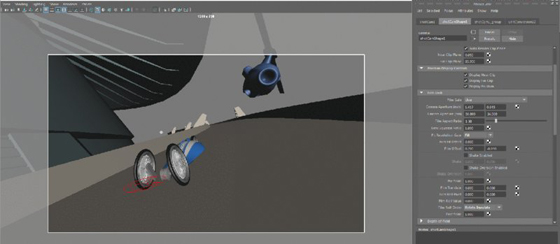
Figure 16.25 Adjusting the Film Offset setting changes the framing of the shot without actually moving the camera or the perspective of the image.
Creating a Camera-Shake Effect
The Shake attribute is an easy way to add a shaky vibrating motion to a camera. The first field is the horizontal shake, and the second field is the vertical shake. The values that you enter in the shake fields modify the current settings for Film Offset. When you are applying a shake, you’re essentially shaking the film back, which is useful because this does not change how the camera itself is animated. You can apply expressions, keyframes, or animated textures to one or both of these fields. The Shake Enabled option allows you to turn the shaking on or off while working in Maya; it can’t be keyframed. However, you can easily animate the amount of shaking over time.
In this example, you’ll use an animated fractal texture to create the camera-shake effect. You can use an animated fractal texture any time that you need to generate random noise values for an attribute. One advantage fractal textures have over mathematical expressions is that they are easier to animate over time.
- Turn on the Shake Enabled option under the Film Back rollout.
- Right-click the first field in the Shake option, and choose Create New Texture from the context menu (see Figure 16.26).
- In the Create Render Node window, choose Fractal from the 2D textures listed in the right column. The camera view will move when you add the texture, and that’s okay.
- The attributes for the fractal texture will appear in the Attribute Editor. Set Amplitude to 0.1.
- Select the Animated check box to enable the animation of the texture, and rewind the animation.
- Right-click the Time attribute, and choose Set Key (see Figure 16.27).
- Set the timeline to frame 200. Set the Time attribute to 100, and set another key.
- Rewind and play the animation; you’ll see the camera move back and forth.
- Repeat steps 2 though 7 for the Vertical setting in Shake to add another animated fractal texture to this attribute. You want to have a different texture for each setting so that the horizontal and vertical shaking settings of the camera are not the same value; otherwise, the camera will appear to shake diagonally.
- In the Attribute Editor for the second fractal texture, expand its UV Coordinates rollout, and click the arrow to the right of it to go to the fractal texture’s place2dTexture2 node.
-
Set the Rotate UV value to 45. This rotates the texture so that the output of this animated texture is different from the other, ensuring a more random motion.
You may notice that the shaking is nice and strong but that you’ve lost the original composition of the frame. To bring it back to where it was, adjust the range of values created by each texture. The Fractal Amplitude of both textures is set to 0.1, which means that each texture is adding a random value between 0 and 0.1 to the film offset. You need to equalize these values by adjusting the Alpha Offset and Alpha Gain settings of the textures.
- With the camera selected, open the Node Editor by choosing Windows ➣ Node Editor.
- Choose the Input and Output Connections icon from the Node Editor toolbar. In the Work Area, you’ll see the two textures connected to the camera.
- Hold the mouse over the line connecting one of the textures to the shotCamShape1 node. The pop-up label shows that the outAlpha attribute of the texture is connected to the vertical or horizontal shake of the camera. This means that you must adjust the outAlpha value to compensate for the change made to the camera’s offset (see Figure 16.28).

Figure 16.26 Right-click the attribute field, and choose Create New Texture. The Create Render Node window will open.

Figure 16.27 To animate a fractal texture, turn on the Animated option and set keyframes on the Time slider.

Figure 16.28 The outAlpha value generated by the animated fractal texture is connected to the camera’s horizontal shake.
If you look at what’s going on with the fractal texture, you’ll see that when the Amplitude setting of the texture is 0, the outAlpha value is 0.5. (You can see this by switching to the shotCamShape1 tab and looking at the Horizontal Shake field.) The fractal texture itself is a flat gray color (value = 0.5). As you increase the Amplitude setting, the variation in the texture is amplified. At an Amplitude value of 1, the outAlpha attribute ranges from 0 to 1. You can see this in the values generated for the Shake attribute in the camera node. This is a large offset and causes the shaking of the camera to be extreme. You can set Amplitude to a low value, but this means that the outAlpha value generated will remain close to 0.5, so as the shake values are added to the film offset, the composition of the frame is changed—the view shifts up to the right.
To fix this, you can adjust the Alpha Gain and Alpha Offset attributes found in the Color Balance rollout of each fractal texture. Alpha Gain is a scaling factor. When Alpha Gain is set to 0.5, the outAlpha values are cut in half; when Alpha Gain is set to 0, outAlpha is also 0, and thus the Shake values are set to 0 and the camera returns to its original position. If you want to shake the camera but keep it near its original position, it seems as though the best method is to adjust the Alpha Gain value of the fractal texture.
However, there is still one problem with this method. You want the outAlpha value of the fractal to produce both negative and positive values so that the camera shakes around its original position in all directions. If you set Alpha Gain to a positive or negative number, the values produced will be either positive or negative, which makes the view appear to shift in one direction or the other. To adjust the output of these values properly, you can use the Alpha Offset attribute to create a shift.
Set Alpha Offset to negative one-half of Alpha Gain to get a range of values that are both positive and negative; 0 will be in the middle of this range. Figure 16.29 shows how adjusting the Amplitude, Alpha Gain, and Alpha Offset attributes affects the range of values produced by the animated fractal texture.

Figure 16.29 You can adjust the range of values produced by the animated fractal texture using the Amplitude, Alpha Offset, and Alpha Gain attributes.
Using an Expression to Control Alpha Offset
You can reduce the number of controls needed to animate the camera shake by automating the Alpha Offset setting on the fractal node. The best way to set this up is to create a simple expression where Alpha Offset is multiplied by negative one-half of the Alpha Gain setting. You can use this technique any time you need to shift the range of the fractal texture’s outAlpha to give both positive and negative values.
- Select the fractal node that has been connected to the camera, and open its attributes in the Attribute Editor. Expand the Color Balance rollout, and set the Alpha Gain value of fractal1 to 0.25.
-
In the field for Alpha Offset, type =–0.5*fractal1.alphaGain;. Then press the Enter key to enter the expression (see Figure 16.30). Note that the correct fractal node must be explicitly stated in the expression or you will get an error. If the node itself is named something other than fractal1, make sure that this is named in the expression accordingly. When in doubt, just look at the top of the Attribute Editor in the Fractal field.
You can create the same setup for the fractal2 node. However, it might be a better idea to create a direct connection between the attributes of fractal1 and fractal2 so that you need only adjust the Alpha Gain of fractal1, and all other values will update accordingly.
- In the Node Editor, click the output port of fractal1 and choose Alpha Gain from the pop-up menu.
- Extend the yellow wire to the input port of fractal2. Choose Alpha Gain from the pop-up menu to make the connection.
- Repeat the procedure for the Alpha Offset and Amplitude to connect these two attributes as well (see Figure 16.31).
- Play the animation, and you’ll see the camera shake. To tone down the movement, reduce the Alpha Gain of fractal1.
- Set the timeline to frame 60, and set the Alpha Gain value of fractal1 to 0. Right-click the Alpha Gain field, and choose Set Key.
- Set the timeline to frame 65. Set the Alpha Gain value of fractal1 to 0.5, and set another key.
- Set the timeline to frame 90. Set the Alpha Gain value of fractal1 to 0, and set a third key.
- Play back the animation, and you’ll see the camera shake as the car and helicopter fly by (make sure that the playback speed in the Time Slider preferences is set to Real-time [24 fps]; otherwise, the shake will not appear at the proper speed in the view window as you play the animation).
- Save the scene as
chase_v03.ma.

Figure 16.30 An expression is created to set the Alpha Offset value of fractal1 automatically to negative one-half of the Alpha Gain value.

Figure 16.31 The Node Editor is used to connect the Alpha Gain, Alpha Offset, and Amplitude of fractal2 to fractal1.
To see a version of the scene to this point, open the chase_v03.ma scene from the chapter16scenes directory at the book’s web page.
The Shake Overscan attribute moves the film back and forth on the z-axis of the camera as opposed to the Shake settings, which move the film back and forth horizontally and vertically. Try animating the Shake Overscan setting using a fractal texture to create some dramatic horror-movie effects.
Creating Custom Camera Rigs
The three camera types in Maya (Camera, Camera and Aim, Camera Aim and Up) work well for many common animation situations. However, you’ll find that sometimes a custom camera rig gives you more creative control over a shot. This section shows you how to create a custom camera rig for the car-chase scene. Use this example as a springboard for ideas to design your own custom camera rigs and controls.
Swivel Camera Rig
This rig involves attaching a camera to a NURBS circle so that it can easily swivel around a subject in a perfect arc:
- Open the
chase_v03.mascene from thechapter16scenesdirectory at the book’s web page, or continue with the scene from the previous section. In the Display tab of the Layer Editor, turn off both the choppers and the buildings layers. - Switch to the persp camera in the viewport.
- Create a NURBS circle by choosing Create ➣ NURBS Primitives ➣ Circle. Name the circle swivelCamRig.
- Create a new camera (Create ➣ Cameras ➣ Camera), and name it swivelCam.
- Open the Attribute Editor for swivelCam to the swivelCamShape tab. Set Controls to Camera and Aim.
- Expand the new swivelCam_group node in the Outliner. Select the swivelCam, and press the f hot key to focus on the camera in the viewport.
- In the Outliner, select swivelCam and Ctrl/Cmd+click the swivelCamRig circle.
- Switch to the Animation menu set, and choose Constrain ➣ Motion Paths ➣ Attach To Motion Path ➣ ❒.
- In the Attach To Motion Path Options dialog box, set Time Range to Start and uncheck Follow.
-
Click Attach to attach the camera to the circle (see Figure 16.32). You may get a warning in the Script Editor when you attach a camera to a curve stating that the camera may not evaluate as expected. You can safely ignore this warning.
The camera is now attached to the circle via the motion path; the camera will stay in a fixed position on the circle curve. This is a fast and easy way to attach any object or other type of transform node (such as a group) to a curve.
- Make sure that the visibility of the street and car display layers is on, and rewind the animation.
- Zoom out in the perspective viewport. In the Outliner, select swivelCamRig and MMB-drag it up in the Outliner into the vehicleAnim group.
- Expand the vehicleAnim group, and select the swivelCamRig.
- Open the Channel Box, and set the Translate and Rotate channels to 0. The circle will be repositioned around the car.
- Select the swivelCam_aim locator from within the swivelCam_group.
- In the Outliner, MMB-drag this up into the vehicleAnim group as well. Set its Translate and Rotate channels to 0. This will move to the pivot point of the vehicleAnim group.
- Select the swivelCamRig and, in the Channel Box, set Translate Y to 0.4. Set the Scale attributes to 0.5 (see Figure 16.33).
- Set the viewport to the swivelCam, and turn on the Resolution Gate display.
- Select the swivelCam node, and set its Focal Length to 20. Play the animation. You’ll see the camera follow along with the car as it drives down the road.

Figure 16.32 The swivelCam is attached to the NURBS circle using the Attach To Motion Path command.

Figure 16.33 The NURBS circle (swivelCamRig) and the swivelCam_aim have been parented to the vehicleAnim group.
Swivel Camera Rig Asset
The camera follows the car, but things don’t get interesting until you start to animate the attributes of the rig. To cut down on the number of node attributes through which you need to hunt to animate the rig, you’ll create an asset for the camera and rig and publish attributes for easy access in the Channel Box.
- In the Outliner, Ctrl/Cmd+click the swivelCam node, swivelCamShape, the swivelCam_aim locator, and the swivelCamRig node.
- Choose Create ➣ Asset ➣ Create Asset ➣ ❒.
- Set Operation to Create Asset, and set the name to swivelCamera. Turn off Include Hierarchy so that only the nodes selected in the Outliner are included.
- Click Apply And Close to create the asset (see Figure 16.34).
- Choose Windows ➣ General Editors ➣ Asset Editor. On the left side of the Asset Editor, select the swivelCamera asset and click the pushpin icon to edit the asset.
- Click the plus sign in the square to expand the swivelCamera asset, and then expand the swivelCam rig node (click the plus sign in the circle next to swivelCamRig).
- From the list of attributes, scroll down to find the Translate attributes. Expand the Translate group by clicking the plus sign in the circle, and select the Translate Y attribute.
- Click the second icon from the top at the center of the Asset Editor. Set the published name to rise.
- Expand the Rotate group, select the Rotate Y attribute, and publish it using the name swivel. Expand the Scale group, select Scale Z, and publish it using the name push.
- On the left side of the editor, expand the swivelCam_aim node, and select its Translate attribute.
- Publish it using the name aim (see Figure 16.35). The three attributes, Aim X, Aim Y, and Aim Z, will be created at once. Maya will automatically capitalize these attributes in the Channel Box.
- Expand the swivelCam (click the plus sign in the square) and the swivelCamShape nodes (click the plus sign in the circle).
- Select the Focal Length attribute, and publish it using the name zoom.
- Close the Asset Editor, and select the swivelCamera asset node in the Outliner. Try changing the values of the published attributes and playing the animation.
- Open the Preferences panel (Windows ➣ Settings/Preferences ➣ Preferences), and select Animation from the Settings category in the column on the left. Make sure that Default In Tangent and Default Out Tangent are set to Clamped.
-
Try setting the following keyframes to create a dramatic camera move using the rig (see Figure 16.36).
FRAME RISE SWIVEL PUSH AIM X AIM Y AIM Z Frame 1 3.227 48.4116 6 0 0 0 Frame 41 0.06 134.265 0.3 0 0 0 Frame 92 0.06 246.507 0.3 0 0.091 0.046 Frame 145 0.13 290.819 0.8 0 0.167 –0.087 Frame 160 0 458.551 0.4 0 0.132 –0.15 Frame 200 0.093 495.166 0.4 0 0.132 –0.15 - Make sure that the view in the perspective window is still set to swivelCam (Panels ➣ Perspective ➣ swivelCam).
- Turn on all of the display layers, and play the animation (see Figure 16.37). Save the scene as
chase_v04.ma.

Figure 16.34 The Create Advanced Asset Options dialog box

Figure 16.35 Various attributes are chosen from the nodes in the swivelCam asset and published to the Channel Box using the Asset Editor.

Figure 16.36 The attributes of the asset are selected and keyframed.

Figure 16.37 A snapshot of the animation using our custom camera rig
To see a finished version of the animation, open the chase_v04.ma scene from the chapter16scenes directory at the book’s web page.
Applying Depth of Field and Motion Blur
Depth of field and motion blur are two effects meant to replicate real-world camera phenomena. Both of these effects can increase the realism of a scene as well as the drama. However, they can both increase render times significantly, so it’s important to learn how to apply them efficiently when rendering a scene. In this section, you’ll learn how to activate these effects and the basics of how to work with them. Using both effects well is closely tied to render-quality issues.
Rendering Using Depth of Field
The depth of field (DOF) settings in Maya simulate the photographic phenomena where some areas of an image are in focus and other areas are out of focus. Artistically, this can greatly increase the drama of the scene, because it forces the viewers to focus their attention on a specific element in the composition of a frame.
Depth of field is a ray-traced effect, and it can be created using both Maya Software and mental ray; however, the mental ray DOF feature is far superior to that of the Maya Software. This section describes how to render depth of field using mental ray.
There are two ways to apply the mental ray depth-of-field effect to a camera in a Maya scene:
- Activate the Depth Of Field option in the camera’s Attribute Editor.
- Add a mental ray physical_lens_dof lens shader or the mia_lens_bokeh lens shader to the camera. (mental ray has special shaders for lights and cameras, as well as surface materials.)
Both methods produce the same effect. In fact, when you turn on the Depth Of Field option in the Depth of Field rollout, you’re essentially applying the mental ray physical DOF lens shader to the camera. The mia_lens_bokeh lens shader is a more advanced DOF lens shader that has a few additional settings that can help improve the quality of the DOF render. For more on lens shaders, consult Chapter 8, “mental ray Shading Techniques.”
The controls in the camera’s Attribute Editor are easier to use than the controls in the physical DOF shader, so this example will describe only this method of applying DOF:
- Open the
chase_v05.mascene from thechapter16/scenesdirectory at the book’s web page. - In the viewport, switch to the DOF_cam camera. If you play the animation (which starts at frame 100 in this scene), you’ll see the camera move from street level upward as two helicopters come into view.
- In the panel menu bar, click the second icon from the left to open the DOF_cam’s Attribute Editor.
- Expand the Environment rollout, and click the Background Color swatch.
- Use the Color Chooser to create a pale blue color for the background (see Figure 16.38).
- Open the Render Settings dialog box, and make sure that the Render Using drop-down list is set to mental ray.
- Choose the Quality tab, and set the Indirect Diffuse (GI) Mode to Final Gather.
- Switch to the Rendering menu set. Choose Render ➣ Test Resolution ➣ 50% Settings (640 × 360). This way, any test renders that you create will be at half resolution, which will save a lot of time but will not affect the size of the batch-rendered images.
-
Set the timeline to frame 136, click in the viewport to set the rendering view, and Choose Render ➣ Render Current Frame to create a test render (refer back to Figure 16.38).
As you can see from the test render, the composition of this frame is confusing to the eye and does not read very well. There are many conflicting shapes in the background and foreground. Using depth of field can help the eye separate background elements from foreground elements and sort out the overall composition.
- In the Attribute Editor for the DOF_cam, expand the Depth Of Field rollout and activate Depth Of Field.
- Store the current image in the Render Preview window (from the Render Preview window menu, choose File ➣ Keep Image In Render View). Click the viewport to set the render view, and then create another test render using the default DOF settings.
-
Use the scroll bar at the bottom of the Render View window to compare the images. There’s almost no discernable difference. This is because the DOF settings need to be adjusted. There are only three settings:
Focus Distance This setting determines the area of the image that is in focus. Areas in front or behind this area will be out of focus.
F Stop This setting describes the relationship between the diameter of the aperture and the focal length of the lens. Essentially, it is the amount of blurriness seen in the rendered image. F Stop values used in Maya are based on real-world F stop values. The lower the value, the blurrier the areas will be beyond the focus distance. Changing the focal length of the lens will affect the amount of blur as well. If you are happy with a camera’s DOF settings but then change the focal length or angle of view, you’ll probably need to reset the F Stop setting. Typically, values range from 2.8 to about 12.
Focus Region Scale You can use this value to adjust the area in the scene that you want to stay in focus. Lowering this value will also increase the blurriness. Use this option to fine-tune the DOF effect once you have the Focus Distance and F Stop settings.
-
Select the DOF_cam, and set Focus Distance to 15, F Stop to 2.8, and Focus Region Scale to 0.1 and create another test render from the DOF_cam.
The blurriness in the scene is much more obvious, and the composition is a little easier to understand. The blurring is grainy. You can improve this by adjusting the Overall Quality slider in the Render Settings. For now, you can leave the settings where they are as you adjust the DOF (see Figure 16.39).
- Save the scene as
chase_v06.ma.

Figure 16.38 A test render is created for frame 136.

Figure 16.39 Adding depth of field can help sort the elements of a composition by increasing the sense of depth.
To see a version of the scene so far, open chase_v06.ma from the chapter16scenes directory at the book’s web page.
Creating a Rack Focus Rig
A rack focus refers to a depth of field that changes over time. It’s a common technique used in cinematography as a storytelling aid. By changing the focus of the scene from elements in the background to the foreground (or vice versa), you control what the viewer looks at in the frame. In this section, you’ll set up a camera rig that you can use to change the focus distance of the camera interactively.
- Continue with the scene from the previous section, or open the
chase_v06.mafile from thechapter16scenesdirectory at the book’s web page. - Switch to the perspective view. Choose Create ➣ Measure Tools ➣ Distance Tool, and click two different areas in the scene to create the tool. Two locators will appear with an annotation that displays the distance between the two locators in scene units (meters for this scene).
- In the Outliner, rename locator1 to camPosition, and rename locator2 to distToCam (see Figure 16.40).
- In the Outliner, expand the DOF_cam_group. MMB-drag camPosition on top of the DOF_cam node to parent the locator to the camera.
- Open the Channel Box for the camPosition locator, and set all of its Translate and Rotate channels to 0; this will snap camPosition to the center of the camera.
- Ctrl/Cmd+click the fields for the camPosition’s Translate and Rotate channels in the Channel Box, right-click the fields, and choose Lock Selected so that the locator can no longer be moved.
- In the Outliner, MMB-drag distToCam on top of the camPosition locator to parent distToCam to camPosition.
- Select distToCam and, in the Channel Box, set its Translate X and Y channels to 0, and lock these two channels (see Figure 16.41). You should be able to move distToCam only along the z-axis.
- Open the Connection Editor by choosing Windows ➣ General Editors ➣ Connection Editor.
- In the Outliner, select the distanceDimension1 node, and expand it so that you can select the distanceDimensionShape1 node. (Make sure that the Display menu in the Outliner is set so that shape nodes are visible.)
- Click the Reload Left button at the top of the Connection Editor to load this node.
- Expand the DOF_cam node in the Outliner, and select DOF_camShape. Click Reload Right in the Connection Editor.
- From the bottom of the list on the left, select Distance. On the right side, select Focus-Distance (see Figure 16.42).
- Look in the perspective view at the distance measured in the scene, select the distToCam locator, and move it so that the annotation reads about 5.5 units.
- Select the DOF_camShape node, and look at its focusDistance attribute. If it says something like 550 units, then there is a conversion problem:
- Select the distanceDimensionShape1 node in the Outliner, and open the Attribute Editor.
- From the menu in the Attribute Editor, click Focus and select the node that reads unitConversion14. If you are having trouble finding the unit conversion node, turn off DAG Objects Only in the Outliner’s Display menu and turn on Show Auxiliary Nodes in the Outliner’s Show menu. You should see the unitConversion nodes at the bottom of the Outliner.
-
Select unitConversion14 to switch to the unitConversion node in the Attribute Editor, and set Conversion Factor to 1.
Occasionally, when you create this rig and the scene size is set to something other than centimeters, Maya converts the units automatically and you end up with an incorrect number for the Focus Distance attribute of the camera. This node may not always be necessary when setting up this rig. If the value of the Focus Distance attribute of the camera matches the distance shown by the distanceDimension node, you don’t need to adjust the unitConversion’s Conversion Factor setting.
- Set the timeline to frame 138. In the Perspective window, select the distToCam locator and move it along the z-axis until its position is near the position of the car (about -10.672 in the Channel Box).
- In the Channel Box, right-click the Translate Z channel and choose Key Selected (see Figure 16.43).
- Switch to the DOF_cam in the viewport, and create a test render. The helicopters should be out of focus, and the area farther up the street in the distance should be in focus.
- Set the timeline to frame 160.
- Move the distToCam node so that it is at about the same position as the closest helicopter (around –1.026).
- Set another keyframe on its Z translation.
- Switch back to the DOF_cam, and render another test frame.
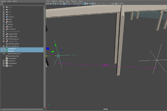
Figure 16.40 A measure tool, consisting of two locators, is created on the grid.

Figure 16.41 The Translate X and Y channels of the distToCam node are locked so that it can move only along the z-axis.

Figure 16.42 The Distance attribute of the distanceDimensionShape1 node is linked to the focusDistance attribute of the DOF_camShape node using the Connection Editor.

Figure 16.43 The distToCam locator is moved near the position of the car on frame 138 and keyframed.
The area around the helicopter is now in focus (see Figure 16.44).

Figure 16.44 The focus distance of the camera has been animated using the rig so that, at frame 160, the helicopter is in focus and the background is blurry.
If you render a sequence of this animation for the frame range between 120 and 180, you’ll see the focus change over time. To see a finished version of the camera rig, open chase_v07.ma from the chapter16scenes directory at the book’s web page.
Adding Motion Blur to an Animation
If an object changes position while the shutter on a camera is open, this movement shows up as a blur. Maya cameras can simulate this effect using the Motion Blur settings found in the Render Settings as well as in the camera’s Attribute Editor. Not only can motion blur help make an animation look more realistic, but it can also help smooth the motion in the animation.
Like depth of field, motion blur is expensive to render, meaning that it can take a long time. Also much like depth of field, there are techniques for adding motion blur in the compositing stage after the scene has been rendered. You can render a motion vector pass using mental ray’s passes and then add the motion blur using the motion vector pass in your compositing software. For jobs that are on a short timeline and a strict budget, this is often the way to go. In this section, however, you’ll learn how to create motion blur in Maya using mental ray.
There are many quality issues closely tied to rendering with motion blur. In this chapter, you’ll learn the basics of how to apply the different types of motion blur.
You enable the Motion Blur setting in the Render Settings window so, unlike the Depth Of Field setting, which is activated per camera, all cameras in the scene will render with motion blur once it has been turned on. Likewise, all objects in the scene have motion blur applied to them by default. You can, and should, turn off the Motion Blur setting for those objects that appear in the distance or do not otherwise need motion blur. If your scene involves a close-up of an asteroid whizzing by the camera while a planet looms in the distance surrounded by other slower-moving asteroids, you should disable the Motion Blur setting for those distant and slower-moving objects. Doing so will greatly reduce render time.
To disable the Motion Blur setting for a particular object, select the object, open its Attribute Editor to its Shape Node tab, expand the Render Stats rollout, and deselect the Motion Blur option. To disable the Motion Blur setting for a large number of objects at the same time, select the objects and open the Attribute Spread Sheet (Windows ➣ General Editors ➣ Attribute Spread Sheet). Switch to the Render tab, and select the Motion Blur header at the top of the column to select all of the values in the column. Enter 0 to turn off the Motion Blur setting for all of the selected objects (see Figure 16.45).
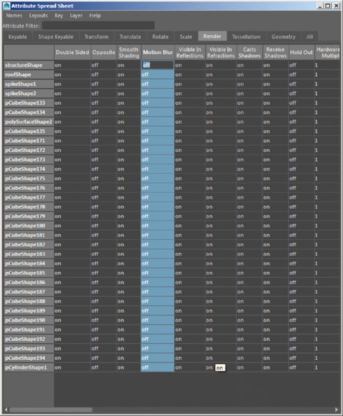
Figure 16.45 You can disable the Motion Blur setting for a single object in the Render Stats section of its Attribute Editor or for a large number of selected objects using the Attribute Spread Sheet.
There are two types of motion blur in mental ray for Maya: No Deformation and Full. No Deformation calculates only the blur created by an object’s transformation—meaning its translation, rotation, and scale. A car moving past a camera or a helicopter blade should be rendered using No Deformation.
The Full setting calculates motion vectors for all of an object’s vertices as they move over time. Full should be used when an object is being deformed, such as when a character’s arm geometry is weighted to joints and animated moving past the camera. Using Full motion blur will give more accurate results for both deforming and nondeforming objects, but it will take a longer time to render than using No Deformation.
The following procedure shows how to render with motion blur:
- Open the scene
chase_v08.mafrom thechapter16scenesdirectory at the book’s web page. - In the Display tab of the Layer Editor, right-click the buildings display layer and choose Select Objects.
- Open the Attribute Spread Sheet (Windows ➣ General Editors ➣ Attribute Spread Sheet), and switch to the Render tab.
- Select the Motion Blur header to select all the values in the Motion Blur column, and type 0 and press Enter to turn the settings to Off (as shown previously in Figure 16.45). Do the same for the objects in the street layer.
- Switch to the Rendering menu set. Choose Render ➣ Test Resolution ➣ Render Settings (1280 × 720). This will set the test render in the Render View window to 1280 × 720, the same as in the Render Settings window.
- Switch to the shotCam1 camera in the viewport.
- Set the timeline to frame 59, and open the Render View window (Windows ➣ Rendering Editors ➣ Render View).
- Create a test render of the current view. From the Render View panel, choose Render ➣ Render ➣ shotCam1. The scene will render.
- In the Render View panel, drag a rectangle over the blue helicopter. To save time while working with motion blur, you’ll render just this small area.
- Open the Render Settings window. Choose Presets ➣ Load Preset ➣ Production.
- Switch to the Scene tab. Expand the Shutter rollout, and set Motion Blur to No Deformation. Leave the settings at their defaults.
-
In the Render View panel, click the Render Region icon (second icon from the left) to render the selected region in the scene. When it’s finished, store the image in the render view. You can use the scroll bar at the bottom of the render view to compare stored images (see Figure 16.46).
In this case, the motion blur did not add a lot to the render time; however, consider that this scene has no textures, simple geometry, and default lighting. Once you start adding more complex models, textured objects, and realistic lighting, you’ll find that the render times will increase dramatically.
-
In the Scene tab of the Render Settings window, take a look at the settings for Motion Blur:
Motion Blur By This setting is a multiplier for the motion blur effect. A setting of 1 produces a realistic motion blur. Higher settings create more stylistic or exaggerated effects.
Motion Steps Increasing Motion Steps forces motion blur to be calculated in between frames.
- For the most part, the Overall Quality setting in the Quality tab is taking care of the look of the motion blur. If the blur is too grainy, increase the Overall Quality value.
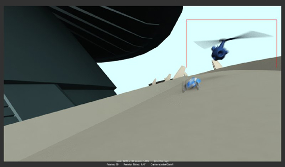
Figure 16.46 The region around the helicopter is selected and rendered using motion blur.
Using Orthographic and Stereo Cameras
Orthographic cameras are generally used for navigating a Maya scene and for modeling from specific views. A stereoscopic, or stereo, camera is a special rig that can be used for rendering stereoscopic 3D movies.
Orthographic Cameras
The front, top, and side cameras that are included in all Maya scenes are orthographic cameras. An orthographic view is one that lacks perspective. Think of a blueprint drawing, and you get the basic idea. There is no vanishing point in an orthographic view.
Any Maya camera can be turned into an orthographic camera. To do this, open the Attribute Editor for the camera and, in the Orthographic Views rollout, turn on the Orthographic option (see Figure 16.47). Once a camera is in orthographic mode, it appears in the Orthographic section of the viewport’s Panels menu. You can render animations using orthographic cameras; just add the camera to the list of renderable cameras in the Render Settings window. The Orthographic Width is changed when you dolly an orthographic camera in or out.

Figure 16.47 The Orthographic option for the perspective camera is activated, flattening the image seen in the perspective view.
Stereo Cameras
You can use stereo cameras when rendering a movie that is meant to be watched using special 3D glasses. Follow the steps in this example to learn how to work with stereo cameras:
- Create a new scene in Maya. From the Create menu, choose Cameras ➣ Stereo Camera. You’ll see three cameras appear on the grid.
- Switch the panel layout to Panels ➣ Saved Layouts ➣ Four View.
- Set the upper-left panel to the perspective view and the upper-right to Panels ➣ Stereo ➣ stereoCamera.
- Use the panel menu in the viewport to set the lower-left viewport to StereoCameraLeft and the lower-right viewport to StereoCameraRight.
- Create a NURBS sphere (Create ➣ NURBS Primitives ➣ Sphere).
- Position the sphere in front of the center camera of the rig, and set its Translate Z channel to –10.
-
In the perspective view, select the center camera and open the Attribute Editor to stereoCameraCenterCamShape.
In the Stereo rollout, you can choose which type of stereo setup you want; this is dictated by how you plan to use the images in the compositing stage. Interaxial Separation adjusts the distance between the left and right cameras, and Zero Parallax defines the point on the z-axis (relative to the camera) at which an object directly in front of the camera appears in the same position in the left and right cameras.
- In the Attribute Editor, under the Stereo Display Controls rollout, set Display Frustum to All. In the perspective view, you can see the overlapping angle of view for all three cameras.
- Turn on Zero Parallax Plane. A semitransparent plane appears at the point defined by the Zero Parallax setting (see Figure 16.48).
- Set the Stereo setting in the Stereo rollout to Converged.
- Set the Zero Parallax attribute to 10.
-
In the perspective view, switch to a top view and make sure that the NURBS sphere is directly in front of the center camera and at the same position as the Zero Parallax plane (Translate Z = –10).
As you change the Zero Parallax value, the left and right cameras will rotate on their y-axes to adjust, and the Zero Parallax Plane will move back and forth depending on the setting.
-
In the top view, move the sphere back and forth, toward, and away from the camera rig. Notice how the sphere appears in the same position in the frame in the left- and right-camera views when it is at the Zero Parallax plane. However, when it is in front of or behind the plane, it appears in different positions in the left and right views.
If you hold a finger up in front of your eyes and focus on the finger, the position of the finger is at the Zero Parallax point. Keep your eyes focused on that point, but move your finger toward and away from your face. You see two fingers when it’s before or behind the Zero Parallax point (more obvious when it’s closer to your face). When a stereo camera rig is rendered and composited, the same effect is achieved and, with the help of 3D glasses, the image on the two-dimensional screen appears in three dimensions.
- Select the center stereo camera, and turn on the Safe Viewing Volume option under the Stereo Display Controls rollout in the Attribute Editor. This displays the area in 3D space where the views in all three cameras overlap. Objects should remain within this volume in the animation so that they render correctly as a stereo image.
- Open the Render Settings to the Common tab.
- Under Renderable Cameras, you can choose to render each camera of the stereo rig separately, or you can select the Stereo Camera (Stereo Pair) option to add both the right and left cameras at the same time. Selecting the stereoCamera option renders the scene using the center camera in the stereo camera rig. This can be useful if you want to render a nonstereoscopic version of the animation.

Figure 16.48 A stereo camera uses three cameras to render an image for 3D movies. The Zero Parallax plane is positioned at the point where objects in front of the center camera appear in the same position in the left and right cameras.
The cameras will render as separate sequences, which can then be composited together in compositing software to create the final output for the stereo 3D movie.
You can preview the 3D effect in the Render View window by choosing Render ➣ Stereo Camera from the Render menu in the Render View. The Render View window will render the scene and combine the two images. You can then choose one of the options in the Display menu of the Render View by selecting Display ➣ Stereo Display menu to preview the image. If you have a pair of red/green 3D glasses handy, choose the Anaglyph option and put on the glasses, and you’ll be able to see how the image will look in 3D.
The upper-right viewport window has been set to StereoCamera, which enables a Stereo menu in the panel menu bar. This menu has a number of viewing options that you can choose from when working in a stereo scene, including viewing through just the left or right camera. Set the shading mode to Smooth Shade All, and switch to Anaglyph mode to see the objects in the scene shaded red or green to correspond with the left or right camera. (This applies to objects that are in front or behind the Zero Parallax plane.)
Using the Camera Sequencer
The Camera Sequencer is a nonlinear editing interface that allows you to stitch together multiple camera views into a single sequence. The Camera Sequencer editing interface itself is similar to editing interfaces found in video editing and compositing programs, but instead of editing a sequence of images, the Camera Sequencer edits the animation of cameras in an existing 3D scene. This allows you to work out the timing of shots in a scene without having to render any images.
This exercise will demonstrate the basic functions of the Camera Sequencer:
- Open the
chase_v09.mascene from thechapter16/scenesfolder at the book’s web page. -
In the perspective viewport, choose Panels ➣ Saved Layouts ➣ Persp/Camera Sequencer (see Figure 16.49).
The Camera Sequencer interface appears at the bottom, below the persp view. Notice that it has its own timeline. When you work with the Camera Sequencer, you do not need to move the playhead on the main Time slider; in fact, this can get a little confusing when you first start using the sequencer, so it is not a bad idea to hide the Time slider.
-
From the main menu bar, choose Display ➣ UI Elements. Uncheck both Time Slider and Range Slider. Hold Ctrl while deselecting to prevent the menu from closing.
Now you can add a camera to the sequencer and start stitching together a sequence from all three cameras.
- From the menu bar in the Camera Sequencer, choose Create ➣ Shot ➣ ❒. Make sure that shot1 is listed in the Name field. Set the Shot Camera menu to shotCam1. Set Start Time to 50 and End Time to 90. Set New Shot Placement to Current Frame. Click the Create Shot button (see Figure 16.50).
-
Hold the Alt key, and drag to the right in the sequencer so that you can see more of the timeline.
When you create the shot, a blue bar is added to the sequencer. This represents the range of shot1. Notice that the shot is placed at the start of the Time slider in the sequencer, even though the shot itself starts at frame 50 (see Figure 16.51).
- Click the Playback Sequence button (the triangle pointed to the right) in the sequencer. The animation shows the car and the helicopter whizzing past the shaking camera.
- Stop the animation, and rewind the playhead in the sequencer by clicking the double triangle button on the far left of the sequencer controls.
-
Choose Create ➣ Shot ➣ ❒ to create a second shot. In the Create Shot Options dialog box, set the shot name to shot2, set Shot Camera to swivelCam, and set Start Time to 40 and End Time to 150. Leave New Shot Placement set to Current Frame. Click the Create Shot button.
A second blue bar appears in the Camera Sequencer editing interface below the shot1 bar on a new track. This is because New Shot Placement was set to Current Frame. You can add the shot to the same track as the original by choosing After Current Shot. I think it’s easier to work with the shots if they are on separate tracks. As you’ll see, you can easily move the tracks around in the Camera Sequencer Editing Interface.
-
In the Camera Sequencer Editing Interface, click the long blue bar in track 2 (turns yellow when selected) and drag it to the right so that the left end of shot2 is below the right end of shot1 (see Figure 16.52).
The numbers at either end of the track correspond to the frame numbers in the animation. The upper number is the frame of the original sequence. The lower number is the frame number in the Camera Sequencer Editing Interface. Look at the blue bar for shot1. The number 41 indicates that you’re on frame 41 in the sequencer. The number 90 indicates that it is frame 90 of the actual animation. At the start of the bar for shot2 (the left end), the number 42 indicates that you’re on frame 42 of the sequence, and the number 40 indicates frame 40 of the actual animation.
-
Click the Playback Sequence button in the sequencer to play the animation. In spite of the fact that technically the animation is jumping backward from the end of shot1 to the start of shot2, it looks seamless. In fact, you could even drag shot1 so that it comes after shot2.
The shot at the top of the stack is what you’ll see when the animation plays.
- Stop the animation, rewind it, and use the Create menu to add a third shot. Name the shot shot3, and set Shot Camera to DOF_camShape, Start Time to 100, and End Time to 150. Leave New Shot Placement set to Current Frame so that the new shot creates a new track. Click the Create Shot button.
- Drag the blue bar for shot3 to the right until the number in the lower-left corner of the bar reads 90. You may need to Alt+MMB-drag to pan the view of the sequencer. Drag the bar up, and place it on the same track with shot1.
-
Play the sequence.
Now things are taking shape. With little effort, you’re already editing a film before a single frame has been rendered!
- Drag the double red vertical line (this is the playhead) until you’re at frame 120 in the sequence. Select the bar for shot2 so that it turns yellow.
- On the menu bar for the Camera Sequencer Editing Interface, click the fifth icon from the left—the icon that looks like two cubes separated by a dotted line. Doing so splits the selected shot at the playhead (see Figure 16.53).
- Click a blank part of the sequencer to deselect the shots, and then click the shorter end of the shot2 bar in the Camera Sequencer Editing Interface. Drag it to the right so that the left end is aligned with the right end of shot3.
- Hold the mouse cursor over the frame number in the upper-right corner of shot2. The cursor looks like a brush. Drag this corner to the right to extend the shot. Drag it all the way until this number reads 200 (see Figure 16.54).
- Play the sequence. Congratulations—you are on your way to becoming a virtual filmmaker!
- Save the scene as
chase_v10.ma. To see a version of this scene, open thechase_v10.mascene in thechapter16/scenesdirectory at the book’s web page.

Figure 16.49 Choose the Persp/Camera Sequencer layout preset.

Figure 16.50 The options for adding a shot to the Camera Sequencer

Figure 16.51 shot1 has been added to the sequencer, indicated by a long blue bar.

Figure 16.52 Move shot2 so that it is aligned with the end of shot1 in the Camera Sequencer Editing Interface.

Figure 16.53 Click the split icon to separate the shot in two.

Figure 16.54 Arrange and extend the shots in the Camera Sequencer Editing Interface to create a seamless animation sequence.
The Camera Sequencer is a powerful tool. In addition to rearranging camera sequences in a nonlinear fashion, you can change the speed of the shots simply by dragging left or right on the frame number in the lower-left or lower-right corners of the shot bar. When you do this, you’ll notice that the percentage value at the center of the bar updates. So if you extend the shot to 200 percent of its original length, the camera moves and the animation in the shot will be slowed down to half speed. If you try this for shot3, you’ll see the blades of the helicopters rotate more slowly than in the original shot. However, the actual animation has not been changed. If you leave the Camera Sequencer as is, the original animation in the scene will not be altered.
You can create an ubercam that incorporates all of the changes created in the Camera Sequencer into a single camera. To do this, choose Create ➣ Ubercam in the Camera Sequencer. The main caveat is that you cannot alter the duration of the shots in the camera sequence.
The Bottom Line
Use assets. An asset is a way to organize the attributes of any number of specified nodes so that the attributes are easily accessible in the Channel Box. This means that members of each team in a pipeline only have to see and edit the attributes they need to get their job done, thus streamlining production.
Master It Create an asset from the nodes in the
miniGun_v04.mascene in thechapter1scenesfolder. Make sure that only the Y rotation of the turret, the X rotation of the guns, and the Z rotation of the gun barrels are available to the animator.
Create file references. File references can be used so that as part of the team works on a model, the other members of the team can use it in the scene. As changes to the original file are made, the referenced file in other scenes will update automatically.
Master It Create a file reference for the
miniGun_v04.mascene; create a proxy from theminiGun_loRes.mascene.
Determine the camera’s image size and film speed. You should determine the final image size of your render at the earliest possible stage in a project. The size will affect everything from texture resolution to render time. Maya has a number of presets that you can use to set the image resolution.
Master It Set up an animation that will be rendered to be displayed on a high-definition progressive-scan television.
Create and animate cameras. The settings in the Attribute Editor for a camera enable you to replicate real-world cameras as well as add effects such as camera shaking.
Master It Create a camera setting where the film shakes back and forth in the camera. Set up a system where the amount of shaking can be animated over time.
Create custom camera rigs. Dramatic camera moves are easier to create and animate when you build a custom camera rig.
Master It Create a camera in the car-chase scene that films from the point of view of chopperAnim3 but tracks the car as it moves along the road.
Use depth of field and motion blur. Depth of field and motion blur replicate real-world camera effects and can add a lot of drama to a scene. Both are expensive to render and therefore should be applied with care.
Master It Create a camera asset with a built-in focus distance control.
Create orthographic and stereo cameras. Orthographic cameras are used primarily for modeling because they lack a sense of depth or a vanishing point. A stereoscopic rig uses three cameras and special parallax controls that enable you to render 3D movies from Maya.
Master It Create a 3D movie from the point of view of the driver in the chase scene.
Use the Camera Sequencer. The Camera Sequencer can be used to edit together multiple camera shots within a single scene. This is useful when blocking out an animatic for review by a director or client.
Master It Add a fourth camera from the point of view of the car, and edit it into the camera sequence created in the section “Using the Camera Sequencer” in this chapter.