
Now that we know how to track planar objects, let's see how to overlay 3D objects on top of the real world. The objects are 3D but the video on our screen is 2D. So the first step here is to understand how to map those 3D objects to 2D surfaces so that it looks realistic. We just need to project those 3D points onto planar surfaces.
Once we estimate the pose, we project the points from the 3D to the 2D. Consider the following image:
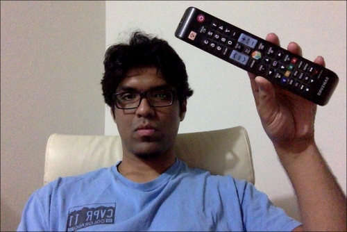
As we can see here, the TV remote control is a 3D object but we are seeing it on a 2D plane. Now if we move it around, it will look like this:

This 3D object is still on a 2D plane. The object has moved to a different location and the distance from the camera has changed as well. How do we compute these coordinates? We need a mechanism to map this 3D object onto the 2D surface. This is where the 3D to 2D projection becomes really important.
We just need to estimate the initial camera pose to start with. Now, let's assume that the intrinsic parameters of the camera are already known. So we can just use the solvePnP function in OpenCV to estimate the camera's pose. This function is used to estimate the object's pose using a set of points. You can read more about it at http://docs.opencv.org/modules/calib3d/doc/camera_calibration_and_3d_reconstruction.html#bool solvePnP(InputArray objectPoints, InputArray imagePoints, InputArray cameraMatrix, InputArray distCoeffs, OutputArray rvec, OutputArray tvec, bool useExtrinsicGuess, int flags). Once we do this, we need to project these points onto 2D. We use the OpenCV function projectPoints to do this. This function calculates the projections of those 3D points onto the 2D plane.
Now that we have all the different blocks, we are ready to build the final system. Let's say we want to overlay a pyramid on top of our cardboard as shown here:

Let's tilt the cardboard to see what happens:

Looks like the pyramid is following the surface. Let's add a second target:

You can keep adding more targets and all those pyramids will be tracked nicely. Let's see how to do this using OpenCV Python. Make sure to save the previous file as pose_estimation.py because we will be importing a couple of classes from there:
import cv2
import numpy as np

from pose_estimation import PoseEstimator, ROISelector

class Tracker(object):
    def __init__(self):
        self.cap = cv2.VideoCapture(0)
        self.frame = None
        self.paused = False
        self.tracker = PoseEstimator()

        cv2.namedWindow('Augmented Reality')
        self.roi_selector = ROISelector('Augmented Reality', self.on_rect)

        self.overlay_vertices = np.float32([[0, 0, 0], [0, 1, 0], [1, 1, 0], [1, 0, 0],
                               [0.5, 0.5, 4]])
        self.overlay_edges = [(0, 1), (1, 2), (2, 3), (3, 0),
                    (0,4), (1,4), (2,4), (3,4)]
        self.color_base = (0, 255, 0)
        self.color_lines = (0, 0, 0)

    def on_rect(self, rect):
        self.tracker.add_target(self.frame, rect)

    def start(self):
        while True:
            is_running = not self.paused and self.roi_selector.selected_rect is None
            if is_running or self.frame is None:
                ret, frame = self.cap.read()
                scaling_factor = 0.5
                frame = cv2.resize(frame, None, fx=scaling_factor, fy=scaling_factor,
                        interpolation=cv2.INTER_AREA)
                if not ret:
                    break

                self.frame = frame.copy()

            img = self.frame.copy()
            if is_running:
                tracked = self.tracker.track_target(self.frame)
                for item in tracked:
                    cv2.polylines(img, [np.int32(item.quad)], True, self.color_lines, 2)
                    for (x, y) in np.int32(item.points_cur):
                        cv2.circle(img, (x, y), 2, self.color_lines)

                    self.overlay_graphics(img, item)

            self.roi_selector.draw_rect(img)
            cv2.imshow('Augmented Reality', img)
            ch = cv2.waitKey(1)
            if ch == ord(' '):
                self.paused = not self.paused
            if ch == ord('c'):
                self.tracker.clear_targets()
            if ch == 27:
                break

    def overlay_graphics(self, img, tracked):
        x_start, y_start, x_end, y_end = tracked.target.rect
        quad_3d = np.float32([[x_start, y_start, 0], [x_end, y_start, 0],
                    [x_end, y_end, 0], [x_start, y_end, 0]])
        h, w = img.shape[:2]
        K = np.float64([[w, 0, 0.5*(w-1)],
                        [0, w, 0.5*(h-1)],
                        [0, 0, 1.0]])
        dist_coef = np.zeros(4)
        ret, rvec, tvec = cv2.solvePnP(quad_3d, tracked.quad, K, dist_coef)
        verts = self.overlay_vertices * [(x_end-x_start), (y_end-y_start),
                    -(x_end-x_start)*0.3] + (x_start, y_start, 0)
        verts = cv2.projectPoints(verts, rvec, tvec, K, dist_coef)[0].reshape(-1, 2)

        verts_floor = np.int32(verts).reshape(-1,2)
        cv2.drawContours(img, [verts_floor[:4]], -1, self.color_base, -3)
        cv2.drawContours(img, [np.vstack((verts_floor[:2], verts_floor[4:5]))],
                    -1, (0,255,0), -3)
        cv2.drawContours(img, [np.vstack((verts_floor[1:3], verts_floor[4:5]))],
                    -1, (255,0,0), -3)
        cv2.drawContours(img, [np.vstack((verts_floor[2:4], verts_floor[4:5]))],
                    -1, (0,0,150), -3)
        cv2.drawContours(img, [np.vstack((verts_floor[3:4], verts_floor[0:1],
                    verts_floor[4:5]))], -1, (255,255,0), -3)

        for i, j in self.overlay_edges:
            (x_start, y_start), (x_end, y_end) = verts[i], verts[j]
            cv2.line(img, (int(x_start), int(y_start)), (int(x_end), int(y_end)), self.color_lines, 2)

if __name__ == '__main__':
Tracker().start()The class Tracker is used to perform all the computations here. We initialize the class with the pyramid structure that is defined using edges and vertices. The logic that we use to track the surface is the same as we discussed earlier because we are using the same class. We just need to use solvePnP and projectPoints to map the 3D pyramid to the 2D surface.