9
Flow Through Nozzles
Contents
9.1 Introduction
9.2 Types of steam nozzles
9.3 Flow of steam through nozzle
9.4 Discharge through nozzle and critical pressure ratio
9.5 Effect of friction and nozzle efficiency
9.6 Supersaturated flow
9.7 Relation between area, velocity and pressure in nozzle flow
9.8 Characteristics of converging–diverging nozzle
9.9 Steam injector
9.10 Questions
9.1 INTRODUCTION
Steam nozzle is an essential device used to generate high kinetic energy. This energy is used for different purposes, namely in injectors to pump feed water into boilers, to maintain vacuum in condensers and also in turbines to run rotors. In steam turbines, the nozzle plays an important role by converting enthalpy of steam into kinetic energy. This chapter deals with steam nozzles and steam injectors. The basic governing equation for nozzles is discussed along with the condition for maximum discharge. The concept of supersaturated flow is also discussed in greater detail.
9.2 TYPES OF STEAM NOZZLES
High-pressure, high-temperature steam from the boiler entering the nozzle expands to low-pressure, low-temperature steam gaining kinetic energy. This high-velocity jet of steam is used to run the turbine. As steam expands in the nozzle its velocity and specific volume both will increase. The dryness fraction will also change due to condensation of steam. As the mass flow rate through the nozzle is constant at any given cross section, the cross section of the nozzle varies according to velocity, specific volume and dryness fraction.
Depending on the cross section of the nozzle, steam nozzles are classified as follows:
1. Convergent nozzle
If the cross section of the nozzle decreases continuously from the entrance to exit, the nozzle is known as convergent nozzle. A convergent nozzle is shown in Figure 9.1(a).

Fig. 9.1 Types of Nozzles
2. Divergent nozzle
If the cross section of the nozzle increases from entrance to exit, such a nozzle is called as divergent nozzle. Figure 9.1(b) shows a divergent nozzle.
3. Convergent divergent nozzle
If the cross section of the nozzle first decreases and then increases, such a nozzle is called as convergent divergent nozzle. The divergent portion of the nozzle increases the pressure ratio beyond the critical value. The area of minimum cross section at which the convergent section ends and divergent section begins is known as throat of the nozzle.
Area of application: It may be noted that in a typical turbine application, converging or subsonic nozzles are generally used. In particular, two available types of nozzles are reamed or foiled type.
Reamed or round nozzles: These nozzles are used in high-pressure impulse stages of steam turbines. These nozzles come with low cost and are characterized by better adaptability to standardization with sharp convergent part and a rounded entrance. However, they possess lower efficiency and underutilize the area of flow annulus. The lengths of the nozzles are often large, the divergence angle being 12°–15°.
Foil nozzles: These nozzles are characterized by aerofoil section with sharp rounded edges and short rounded exit, enabling a better issuing jet. They are costly to manufacture but have higher efficiency. They are used in large steam turbines.
9.3 FLOW OF STEAM THROUGH NOZZLE
Consider the flow of steam through a convergent nozzle between sections 1 and 2 as shown in Figure 9.2.

Fig. 9.2 Flow Through a Nozzle
Let
h1, h2 = Enthalpy/kg of steam at sections 1 and 2, respectively, kJ/kg
V1, V2 = Velocity of steam at sections 1 and 2, respectively, m/s
w = Work done/kg of steam
q = Heat transferred/kg of steam
Applying steady flow energy equation at sections 1 and 2, we have
![]() (1)
(1)
For nozzles, expansion is assumed as isentropic.
Hence, w = 0 and q = 0. This means nozzle is neither a work-absorbing nor a work-generating device.
Equation (1) is now modified to
![]()
∴ ![]()
∴  (2)
(2)
The above equation gives exit velocity of steam through the nozzle.
But usually the velocity of steam entering the nozzle is negligible compared with exit velocity.
Hence, ignoring V1 in the above Equation (2), we have
![]() (3)
(3)
= ![]()
where h1 and h2 are in kJ/kg.
Equation (3) gives the general expression for the exit velocity of steam from the nozzle irrespective of its shape.
Note: Expansion through the nozzle is neither free expansion nor throttling. This is evident from Equation (2). When steam expands through the nozzle, the loss in enthalpy is gained in the form of kinetic energy.
Exit velocity through the nozzle if the expansion is polytropic can be determined as follows:
Let us assume that expansion follows the law pv n = constant, where n = polytropic index
Work done during the flow process, if the expansion is polytropic, is given by
W = ![]() (4)
(4)
For a nozzle, this work is equal to work done during expansion, which in turn is equal to change in kinetic energy.
∴ ![]() =
= ![]() (5)
(5)
Ignoring the velocity of steam at entry, Equation (5) modifies to
![]() =
= ![]() (6)
(6)
According to polytropic law
![]()
or ![]() =
= ![]() (7)
(7)
Substituting (7) in (6)
![]() =
= 
= 
V2 =  (8)
(8)
9.4 DISCHARGE THROUGH NOZZLE AND CRITICAL PRESSURE RATIO
Nozzles should always be designed for maximum discharge. Discharge through the nozzle is determined by applying continuity equation.
Let m = Mass flow rate of steam through the nozzle, kg/s
A2 = Cross-section area at the nozzle exit, m2
V2 = Velocity at the nozzle exit, m/s
v2 = Specific volume of steam at nozzle exit, m3/kg
Mass flow rate or discharge through the nozzle is given by
m = ![]() (1)
(1)
If expansion is polytropic, then exit velocity
V2 = 
Substituting rp = pressure ratio = ![]() , we have
, we have
V2 =  (2)
(2)
Substituting (2) in (1), we have
m =  (3)
(3)
But ![]()
∴ ![]() =
=  =
= (4)
(4)
Substituting (4) in (3)
m = 
m =  (5)
(5)
(i) Optimum pressure ratio or critical pressure ratio
The above equation gives the discharge of steam through a convergent nozzle. It can be observed that discharge through the nozzle mainly depends on the pressure ratio for a given value of n. Thus, for maximum discharge through the nozzle
![]() = 0
= 0

or 
∴ ![]()
or ![]() =
=![]()
![]() =
= ![]()
Or ![]()
![]() =
=  = rpc(6)
This equation gives the optimum pressure ratio for maximum discharge. It is also known as critical pressure ratio.
Note:
For saturated steam
n = 1.135
∴ rp = ![]() = 0.58
= 0.58
For superheated steam
n = 1.3
∴ rp = ![]() = 0.546
= 0.546
(ii) Maximum discharge
The maximum mass flow rate from the nozzle occurs at critical pressure ratio.
Substituting Equation (6) in Equation (5), we have
(m)max = 
= 
= 
= 
(m)max = 
(m)max =  (7)
(7)
(iii) Maximum velocity
Maximum velocity through the nozzle for maximum discharge can be determined as follows:
Maximum velocity
V2 = 
(V2)max = 
= 
(V2)max = ![]() (8)
(8)
Figure 9.3 shows the variation of mass flow, rate, steam velocity and specific volume with back pressure for a convergent–divergent nozzle.

Fig. 9.3 Variation of m, V and v with Respect to Back Pressure
9.5 EFFECT OF FRICTION AND NOZZLE EFFICIENCY
When steam expands in the nozzle, steam pressure drops on account of the following reasons:
- Friction existing between nozzle surface and steam and also internal fluid friction in steam.
- Losses due to shock.
Due to friction the exit velocity of steam reduces, and both dryness fraction and specific volume increase as evident from Figure 9.4.

Fig. 9.4 Effect of Friction During Flow Through a Nozzle
In Figure 9.4, line 1–2–3 shows isentropic expansion process through a nozzle without friction. But due to friction expansion follows as shown in line 1–2–3′. In case of a convergent–divergent nozzle, maximum friction loss occurs between the throat and exit. Thus
Isentropic enthalpy drop = h1 − h3
Actual enthalpy drop due to friction = h1 − h3′
It is evident that (h1 − h3′) < h1 − h3, which means that there is reduction in enthalpy drop under the influence of friction. Hence, there will be subsequent reduction in exit velocity of steam.
Further, due to friction, the final state of steam is corresponding to point 3′ instead of point 3. But, dryness fraction of steam at 3′ is higher than dryness fraction of steam at 3. Thus, under the influence of friction steam becomes more wet.
Similarly, the specific volume of steam at point 3′ is higher compared with specific volume of steam at 3. Hence, specific volume of steam also increases due to friction.
We can summarize the effect of friction as follows:
- The expansion is not isentropic
- Enthalpy drop is reduced, which results in reduced exit velocity
- Final dryness fraction of steam increases, i.e. steam becomes more wet
- Specific volume of steam increases
Due to friction efficiency of the nozzle is reduced. Nozzle efficiency is given by
ηn = ![]()
ηn = ![]()
Exit velocity of steam from the nozzle can be modified to
V2 = ![]()
where (Δh)i = Isentropic enthalpy drop.
9.6 SUPERSATURATED FLOW
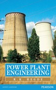
Consider the isentropic expansion of superheated steam in a nozzle from pressure p1 to pressure pb as shown in Figure 9.5 by the line 1–2–3. Under normal condition, condensation of steam must begin at point 2 (vapour phase changes to liquid phase below the saturation curve). But due to the high velocity of steam passing through the nozzle at sonic or supersonic speed, time available for condensation at point 2 is only a fraction of a second (about 0.001 s). Because of this, steam expands further in its vapour phase beyond the saturation curve corresponding to pressure p3 and point 2′ by an amount 2–2′. Thus, steam remains dry even along the line passing through point 2′. This line, which is a limit to the supersaturated state, is known as Wilson line.
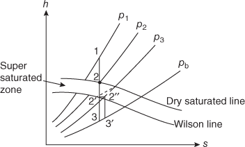
Fig. 9.5 Metastable Flow
The vapour between pressures p2 and p3 is said to be supersaturated or super cooled. This is because between points 2 and 2′ corresponding to pressures p2 and p3, respectively, the temperature of vapour is lesser than the corresponding saturation temperature. The difference between these temperatures is known as degree of undercooling and the flow is known as supersaturated flow or metastable flow.
After reaching the Wilson line corresponding to point 2′, partial condensation begins at constant enthalpy along the line 2′–2″. Due to partial condensation of steam, heat is released which further raises the steam temperature to saturation temperature. Further, steam expands isentropically to back pressure along 2″–3′.
For supersaturated flow, the following relations are used for calculation purpose:
- 1. Exit velocity of steam at the end of expansion
V2 =

- Specific volume
v2 =

- Apparent temperature
T2 =

9.7 RELATION BETWEEN AREA, VELOCITY AND PRESSURE IN NOZZLE FLOW
Consider flow through a nozzle as shown in Figure 9.6. Let us further consider two sections 1–1 and 2–2 over a small distance δx. Assuming steady, isentropic and uniform flow across any cross section, we have
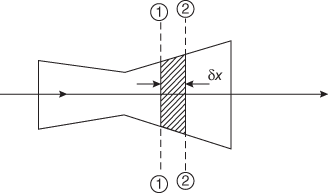
Fig. 9.6 Variation of Area, Velocity and Volume in a Nozzle
At section 1–1, m = ![]()
At section 2–2, m = ![]()
where δA, δV and δv are small increments in area, velocity and specific volume between the two sections, respectively.
Using continuity equation,
m = ![]() =
= ![]()
On simplifying
![]() = 0
= 0
or between the limits
![]() = 0(1)
= 0(1)
For an isentropic flow
pvγ = constant = C
∴ lnp + γ lnv = lnC(2)
Differentiating Equation (2) and dividing throughout by pv
![]() = 0
= 0
or ![]() =
= ![]()
Applying steady flow energy equation between the two sections, we have
δq = ![]()
For a nozzle δq = 0 and δw = 0
∴ ![]() = 0
= 0
But dh = Tds + vdp = vdp (for isentropic flow)
Substituting in the above equation
![]() = −vdp
= −vdp
or VdV = −vdp
or ![]() = −
= −![]()
![]()
From Equation (1)
![]()
![]() =
= ![]()
= 
![]() =
= ![]() (3)
(3)
where C = ![]() = Sonic velocity
= Sonic velocity
M = ![]() = Mach number
= Mach number
1. Accelerated flow
For accelerated flow dp is negative in Equation (3), which means pressure decreases along the flow direction (Figure 9.7).

Fig. 9.7 Accelerated Flow (Nozzle)
- When V < C or M < 1, dA is negative; nozzle is convergent and flow is subsonic.
- When V > C or M > 1, dA is positive; nozzle is divergent and flow is supersonic.
2. Decelerated flow (diffuser)
For decelerated flow dp is positive in Equation (3), which means pressure increases along the flow direction (Figure 9.8).

Fig. 9.8 Decelerated Flow (Diffuser)
- When V < C or M < 1, dA is positive; diffuser is converging and velocity is supersonic.
- When V > C or M > 1, dA is negative; diffuser is diverging and velocity is subsonic.
It may be noted that Equation (3) may also be reduced to the following form:
![]() (4)
(4)
Note:
- At subsonic speeds (M < 1), a decrease in area increases the speed of flow. Hence, a subsonic nozzle assumes a convergent profile and a subsonic diffuser assumes a divergent profile. The flow behaviour therefore qualitatively remains the same as in incompressible flows in the region of M < 1.
- At supersonic speeds (M > 1), the effect of area changes are different. According to Equation (4), a supersonic nozzle must assume a divergent profile with an increasing area in the flow direction, whereas a supersonic diffuser must be a converging channel. Divergent nozzles are used in missiles and launch vehicles to generate supersonic flow.
- 3. Figure 9.9 shows the arrangement of nozzles and diffusers to generate the required flow based on Mach Number, M.

Fig. 9.9 Arrangement of Nozzles and Diffusers
9.8 CHARACTERISTICS OF CONVERGING–DIVERGING NOZZLE
Consider a converging–diverging nozzle (De Laval nozzle) as shown in Figure 9.10.

Fig. 9.10 Converging–Diverging Nozzle
Let subscript 0 represent stagnation condition and let us assume that the stagnation enthalpy and pressure at the inlet are known. The pressure at the nozzle exit is pE, back pressure is pB and critical pressure is p*.
Before making the analysis, let us see how pressure distribution occurs in a converging nozzle as shown in Figure 9.11.

Fig. 9.11 Pressure Distribution in a Convergent Nozzle
When the back pressure is varied by operating the valve, the mass flow rate and the exit plane pressure pB/p0 also varies as shown in Figure 9.12.

Fig. 9.12 Variation of Mass Flow Rate and Exit Pressure versus Back Pressure in a Convergent Nozzle
- When pB/p0 = 1, there is no flow and pE/p0 = 1, as shown by point 1.
- By decreasing the pressure to point 2 such that pB/p0 ⟩ p*/p0, then pE = pB and ME ⟨ 1, flow is subsonic.
- By decreasing the pressure to point 3(critical pressure) such that pE = pB, the Mach number ME = 1, flow is sonic.
- By decreasing the pressure to point 4 (below the critical pressure) such that pE = p* and the Mach number ME = 1, there will be no further increase in mass flow rate. The drop in pressure from pE to pB occurs outside the nozzle exit and this limit is known as choking limit. Choking limit refers to the maximum possible mass flow through the nozzle irrespective of further decrease in exit pressure.
Let us now consider a convergent–divergent nozzle to understand the pressure distribution and the phenomenon of shock as shown in Figure 9.13.

Fig. 9.13 Pressure Distribution in a Convergent– Divergent Nozzle
In case of a convergent–divergent nozzle
- When pB/p0 = 1, there is no flow as shown by curve 1.
- By decreasing the pressure to point 2 such that pB/p0 ⟨ 1, but pB/p0 ⟩ p*/p0, the velocity in the converging section while M ⟨ 1 at the throat. In the diverging section, which acts as a subsonic diffuser, pressure increases and velocity decreases.
- By decreasing the pressure to point 3, flow becomes sonic at the throat (Mach number M = 1), and diverging portion still functions as a diffuser, reducing the flow speed from sonic to subsonic.
- By decreasing the exit pressure below the point as specified by curve 4, such that pE = pB, the diverging section acts as a supersonic nozzle as pressure reduces and velocity increases continuously. The flow is isentropic and the pressure ratio corresponds to designed conditions.
- By decreasing the pressure ratio further to point 5, there will be no further decrease in exit pressure. The drop in pressure from pE to pB occurs outside the nozzle exit.
The flow is not isentropic between pressures corresponding to curves 3 and 4 in the diverging section. This is due to the phenomenon known as shock where the flow that starts accelerating downstream of the throat suddenly decelerates at a certain section through a nearly normal surface of discontinuity. At supersonic speeds, shocks occur and subsequently flow becomes subsonic; after that the rest of the duct acts like a diffuser. By gradually lowering the exit pressure pE, the position of shock moves down the nozzle and finally disappears at the exit end, when pE reaches a value corresponding to point 4.
Note: When M = 1 at the throat, the discharge is maximum and the nozzle is said to be choked. At this point, the nozzle is incapable of allowing more discharge even if the exhaust pressure is reduced further. Hence, the discharge corresponding to this condition is also known as critical discharge.
9.9 STEAM INJECTOR
A steam injector is a device used to supply feed water at high pressure to the boiler. It works similar to a steam nozzle. Figure 9.14 shows the working of a steam injector. High-pressure steam from the boiler passes through a convergent nozzle. The high-velocity steam coming from the convergent nozzle mixes with the feed water coming from the feed tank in the combined nozzle. The kinetic energy of the mixture is converted into pressure energy in the divergent portion of the combined nozzle. High-pressure water then enters the water nozzle from where it is delivered to the boiler at boiler pressure. Water, which overflows during starting, is collected in an overflow chamber and then discharged to the drain.

Fig. 9.14 Steam Injector
Example 9.1
Find the velocity of steam issuing from a nozzle in which the steam has been expanded in an initial condition of 10.3 bar absolute dry to a pressure of 0.686 bar (i) neglecting friction and (ii) considering frictional loss as 10 per cent of the heat drop.
Solution: From Mollier chart
Heat drop = 456 kJ/kg = (h1 − h2)
Velocity V2 = ![]()
V2 = ![]()
= 954.96 m/s
ηnozzle = 90%
∴ V2 = ![]()
= ![]()
= 905.95 m/s.

∴ Diameter of nozzle mouth
d = ![]()
d = 3.34 cm.
Example 9.2
Steam at a pressure of 6.85 bar and 0.9 dry expands through a nozzle having a throat area of 4.65 cm2. The back pressure is 1.03 bar. Determine (i) the mass of steam flowing per minute; (ii) the diameter of the mouth of nozzle for maximum discharge; and (iii) the final velocity of the steam.
Solution: Since the steam is saturated, for the maximum discharge, theoretical pressure at the throat of nozzle will be
p2 = 0.58p1
= 0.58 × 6.85
= 3.97 bar
From Mollier chart, the heat drop from the inlet of nozzle to the nozzle throat is
h1 = h2 = 92.95 kJ
Dryness fraction
x2 = 0.872
∴ Velocity of steam at throat
V2 = ![]()
V2 = 431 m/s
From steam tables, the specific volume of steam at nozzle throat is
V2 = 0.463 m3/kg
- Mass flow rate, m =

= 0.496 kg/s.
- Again from Molliar chart, heat drop from the inlet to the mouth of nozzle is
h1 = h3 = 297 kJ
x3 = 0.83
From steam tables, the specific volume of steam is
v3 = 1.64 m3/kg
Velocity of steam at the nozzle mouth is
V3 =
 = 771 m/s
m =

A3 =

A3 = 8.757 cm2.

Example 9.3
Dry saturated steam enters a convergent nozzle at a pressure of 10 bar with a velocity of 90 m/s. The exit pressure is 5 bar and steam leaves the nozzle at a velocity of 435 m/s. The friction is 8 kJ/kg of steam flow. Determine
- Velocity coefficient
- Final dryness fraction
- Area at the exit if the inlet area is 1260 mm2
Solution: Neglecting losses
![]() (1)
(1)
at 10 bar h1 = 2776.2 kJ/kg v1 = 0.1943 m3/kg
at 5 bar hw2 = 640.1 kJ/kg ![]() = 2107.4 kJ/kg
= 2107.4 kJ/kg
From (1)
![]()
h2 = 2685.64 kJ/kg
isentropic enthalpy drop = h1 − h2
= 2776.2 − 2685.64
= 90.56 kJ/kg
Actual enthalpy drop, h1 − h2 = (90.56 − 8)
= 82.56 kJ/kg

- Velocity coefficient
Velocity coefficient =

=

=

= 0.95.
- Final dryness fraction
h1 − h2′ = 82.56
h2′ = (2776.2 − 82.56)
= 2693.64
But, h2′ =

= 640.1 + 2107.4
640.1 + x2 2107.4 = 2693.64
x2′ = 0.97.
- Area at exit A2


A2 = 487.6 mm2
Example 9.4
Steam at 15 bar and 300°C expands in a nozzle to a pressure of 1 bar. If the efficiency of the nozzle is 80 per cent, calculate the mass of steam discharged when the exit area is 0.18 × 10⁻³ m2.
Solution:
Initial pressure p1 = 15 bar
Final pressure p2 = 1 bar
Exit area A2 = 0.18 × 10⁻³ m2
Nozzle efficiency = 0.80%
Friction factor = 0.80.
From Mollier chart
h1 = 3037 kJ/kg
h2 = 2515 kJ/kg
x2′ = 0.93.
From steam tables vs2 = 1.6937 m3/kg
Exit velocity v2 = ![]()
= ![]()
= 914 m/s.
Mass of steam discharged,
m = ![]()
= ![]()
= 0.105 kg/s.
9.10 Questions
9.10.1 Objective Questions
- A fluid is flowing through a nozzle from 1 to 2 as shown in the figure.

It can be concluded that


- Cannot be concluded

- In a steam nozzle if subscripts 1 and 2 represent inlet and outlet conditions and p1, v1, T and Ts are pressure, specific volume, temperature and saturation temperature of steam, which of the following ratios is less than 1?
- Function of the steam nozzle is to convert
- enthalpy of steam into kinetic energy
- enthalpy of steam into pressure energy
- enthalpy of steam into pressure energy
- none of these
- In a steam nozzle velocity at inlet V1 and velocity at outlet V2 are related as
- V1 = V2
- V1 > V2
- V2 > V1
- None of these
- In a steam nozzle enthalpy at inlet h1 and enthalpy at outlet are related as
- h1 = h2
- h1 > h2
- h2 > h1
- None of these
- For a steam nozzle having varying area passage A, which of the following relations are true?
- Expansion of steam through the nozzle is assumed as
- adiabatic
- polytropic
- isothermal
- isochoric
- In the convergent section of a nozzle, Mach number M is
- M > 1
- M = 1
- M < 1
- M = 0
- At the throat of the nozzle Mach number is
- M > 1
- M = 1
- M < 1
- M = 0
- The critical pressure ratio for maximum discharge through the nozzles is
- For superheated flow through nozzle
- For saturated flow through nozzle
- Critical pressure ratio for superheated steam is
- 0.545
- 0.578
- 0.530
- 0.587
- Critical pressure ratio for dry saturated steam is
- 0.545
- 0.578
- 0.530
- 0.587
- Friction in the nozzle
- reduces exit velocity
- increases specific volume
- increases dryness fraction
- all of the above
- For a well-designed nozzle friction loss is limited to
- 0−5%
- 5−10%
- 10−15%
- 15−20%
- Zeuner's relation, to determine index of expansion η for flow through a nozzle is
- η = 1.035 + 1x
- η = 1.135 + 0.1x
- η = 1.035 + 0.1x
- η = 1.135 − 0.1x
- For supersaturated flow through a nozzle
- The exit velocity (V2) through a nozzle is given by
- The cross section of the nozzle is
- circular
- square
- elliptical
- all of these types
- If the exit pressure is equal to or more than critical pressure
- a convergent nozzle is used
- a divergent nozzle is used
- a convergent–divergent nozzle is used
- none of these
- If the exit pressure is less than the critical pressure
- a convergent nozzle is used
- a divergent nozzle is u sed
- a convergent–divergent nozzle is used
- none of these
- At the throat of the nozzle
- ratio V/v is maximum and A is minimum
- ratio V/v is minimum and A is minimum
- ratio V/v is maximum and A is maximum
- ratio V/v is minimum and A is maximum
- For supersonic and subsonic flow through the nozzle
- pressure decreases and velocity decreases
- pressure increases and velocity decreases
- pressure decreases and velocity increases
- pressure remains constant but velocity increases
- Friction in nozzle
- increases mass flow rate
- does not affect mass flow rate
- decreases mass flow rate
- none of these
- When a nozzle is operated below its designed value, it is known as
- under expanding
- over expanding
- choked
- stalled
- A steam nozzle is said to be choked when
- flow rate through it is completely stopped
- flow rate through it is maximum
- flow rate through it is minimum
- none of these
- Under maximum discharge conditions, the flow velocity in the convergent section of the nozzle is given by Mach number
- M = 1
- M < 1
- M > 1
- None of these
- Wilson's line is a characteristic of
- saturated flow through nozzle
- supersaturated flow through nozzle
- friction horse power
- none of these
- Supersaturated flow through the nozzle means
- expansion of steam beyond the saturation line
- expansion of steam up to the saturation line
- expansion of steam above the saturation line
- none of these
- Supersaturated flow through the nozzle occurs due to
- short time interval available for expansion
- long time interval available for expansion
- insufficient time available for expansion
- none of these
- Shock waves in the nozzle are generally observed
- in the convergent section of the nozzle
- in the divergent section of the nozzle
- at the entry of the nozzle
- none of these
- The effect of supersaturated flow through the nozzle is
- reduction in heat drop
- increase in entropy
- decrease in exit velocity
- all of the above


Answers
- a 2. b 3. a 4. c 5. b 6. a 7. a 8. c 9. b 10. b 11. a 12. a 13. a 14. b 15. d 16. b 17. c 18. b 19. b 20. d 21. b 22. a 23. b 24. c 25. b 26. d 27. b 28. b 29. b 30. a 31. a 32. b 33. d
9.10.2 Review Questions
- What do you understand by the term critical pressure as applied to steam nozzles?
- Why are turbine nozzles made divergent after the throat?
- Explain the term nozzle efficiency.
- A convergent–divergent nozzle is required to discharge 360 kg of steam per hour. The nozzle is supplied with steam at 10 bar and 0.97 per cent dry and discharges against a back pressure of 0.5 bar. Neglecting the effect of friction and using H–s chart, the throat and exit diameters.
- Steam at a pressure of 10 bar and 0.98 per cent dry is passed through a convergent–divergent nozzle to a back pressure of 0.1 bar. The mass flow rate is 0.55 kg/s. Find
- pressure at the throat and
- number of nozzles used if each nozzle has a throat area of 0.5 cm2.
The enthalpy drop used for reheating the steam by friction in the divergent part is 10 per cent of the overall isentropic drop.
Take index of expansion = 1.13.
- A convergent–divergent nozzle is required to discharge 350 kg of steam/hour. The nozzle is supplied with steam at 8.5 bar and 90 per cent dry and discharge against a back pressure of 0.4 bar. Neglecting the effect of friction, find the throat and exit areas. Show the process on H–s diagram.