16
Nuclear Power Plants
Contents
16.1 Introduction to nuclear engineering
16.2 Radioactive decay, half life
16.3 Principles of release of nuclear energy
16.4 Nuclear reactor components
16.5 Classification of nuclear reactors
16.6 Thermal fission reactors and power plant and their location
16.7 Reactor control
16.8 Radiation hazards
16.9 Nuclear power generation in india
16.10 Questions
16.1 INTRODUCTION TO NUCLEAR ENGINEERING
With the acute shortage of other sources of energy, namely fossil-based fuels and hydel source, the use of nuclear energy has become an inevitable option for both developed and developing countries. The amount of heat generated by burning 1 kg of nuclear fuel is equivalent to the energy generated by burning 3000 tonnes of coal or 1600 tonnes of oil.
The most important advantage of nuclear energy is that it has no combustion by-products and under safe working conditions contributes no pollutant to air. Site selection for producing nuclear energy is completely independent of geographical area and it requires no fuel transportation networks and large storage facilities. However, nuclear wastes from a power plant are more hazardous and face severe disposing problems.
In this chapter, a brief study of nuclear energy, nuclear reactions, basic definitions, nuclear reactors and nuclear waste disposal is made.
Advantages of nuclear power plant
- Less space requirement
- Consumes very small quantity of fuel
- Fuel transportation cost is less
- Large fuel storage facility is not required
- Reliable in operation
- Not affected by changes in weather conditions
Disadvantages
- High initial and maintenance costs
- Not suitable for varying load conditions
- Radioactive wastes should be disposed off carefully
- Requires trained operators
16.1.1 Atomic Structure
Atom consists of a relatively heavy, positively charged nucleus and a number of much lighter negatively charged electrons. Electrons exist in various orbits around the nucleus. The nucleus consists of two sub-particles known as nucleons (Figure 16.1).

Fig. 16.1 Atomic Structure
The electric charge on the proton is equal in magnitude but opposite in sign to that of electron. The atom as a whole is electrically neutral. The number of protons is equal to the number of electrons in orbit.
One atom may be transformed into another by losing or gaining some of the sub-particles. This results in mass change Δm and enormous amount of energy is released (or absorbed). According to Einstein's law
ΔE = Δmc2(1)
where c = speed of light in vacuum
Energy from nuclear reactions can be estimated by using the above Equation (1).
ΔE = ![]()
If mass is in kg, gc = 1 kg m/Ns2
ΔE = 9 × 10¹⁶ Δm in J
If mass is in amu and energy is in MeV
ΔE (in J) = 1.49 × 10⁻¹⁰ Δm (in amu)
ΔE (in MeV) = 931 Δm (in amu)
where
1 amu = 1.66 × 10⁻²⁷ kg
1 eV = 1.6021 × 10⁻¹⁹ J
Figure 16.2 shows the atomic structure of Hydrogen and Helium.

Fig. 16.2 Atomic Structure of Hydrogen and Helium
Most of the mass of atom is in the nucleus. The masses of three atomic subparticles are
Neutron mass, mn = 1.008665 amu
Proton mass, mp = 1.007277 amu
Electron mass, me = 0.0005486 amu
1 amu (atomic mass unit) = 1.66 × 10⁻²⁴ g
16.1.2 Some Definitions
1. Atomic number
Number of protons in the nucleus is called atomic number Z. It is unique for each chemical element and represents both the number of positive charges on the central massive nucleus of the atom and the number of electrons in orbits around the nucleus. The maximum allowed numbers of electrons in orbits as Z increases for the first few shells are 2, 8 and 18.
2. Mass number
The total number of nucleons in the nucleus is called the mass number A. Nuclear symbols are written as ![]() , where X is the chemical symbol.
, where X is the chemical symbol.
The masses of atoms are compared on a scale in which an isotope has a mass of exactly 12.
1 amu
= ![]() the mass of
the mass of ![]()
= 1.66 × 10⁻²⁴ g
Thus, A = 1.66 × 10−24 = mass of the atom.
3. Binding energy
The nuclear force acts only when the nucleons are very close to each other and binds them into a compact stable structure. The energy associated with this force (potential energy) is known as binding energy.
To disrupt a nucleus and separate it into its component nucleons, energy must be supplied from outside.
Let
M = mass of an atom (mass of nucleus + electrons)
mn = mass of neutron
mH = mass of proton electron
N = neutron number (A − Z)
Then, binding energy
B = Nmn + ZmH − M
e.g. Binding energy of tritium
B = (3 − 1)1.00866 + 1(1.00782) − 3.01702
= 0.00812 amu
4. Valence electrons
Electrons that orbit in the outermost shell of an atom are known as valence electrons. The outermost shell is called valence shell.
5. Isotopes
Atoms with nuclei having the same number of protons and similar in physical and chemical characteristics but differing in masses are known as isotopes.
e.g. Deuterium is an isotope of hydrogen
6. Atomic number
The number of protons in the nucleus is called atomic number Z.
16.2 RADIOACTIVE DECAY, HALF LIFE
16.2.1 Radioactive Decay
All isotopes of heavier elements starting from atomic number Z = 84 (polonium) posses weak binding energy/nucleon and have the tendency to emit radiation until a more stable nucleus is formed. This new nucleus is called daughter and the original nucleus is called parent. This is a spontaneous disintegration process, known as radioactive decay.
Radioactive isotopes may be either natural or artificial and are known as radioisotopes. Radioactivity is characterized by either decrease in mass or liberation of energy (in the form of kinetic energy) accompanied by electromagnetic radiation.
An example of radioactivity is
![]()
Naturally occurring radioisotopes undergo the following types of decay:
1. Alpha decay
A nucleus undergoes alpha decay if it emits an α-particle that is identical to a helium nucleus.
2. Beta decay
A nucleus undergoes β decay if the energy released in the decay process creates a β-particle that is identical to a high-speed electron.
![]()
In β− decay, a β− particle (high-speed electron) and an antineutrino, ![]() , are produced. β− particles are likely to produce nuclides having high neutron-to-proton ratios. The net effect of this is to ‘convert neutron to proton’ (Figure 16.3).
, are produced. β− particles are likely to produce nuclides having high neutron-to-proton ratios. The net effect of this is to ‘convert neutron to proton’ (Figure 16.3).
![]()

Fig. 16.3 β− Decay
In β+ decay, a high-speed electron and a neutrino, v, are produced. β− particles are likely to produce nuclides having low neutron-to-proton ratios. The net effect of this is to ‘convert proton to neutron’ (Figure 16.4).
![]()

Fig. 16.4 β+ Decay
3. Spontaneous fission
It is a slow process in which a heavy nuclide is split into lighter nuclides with similar mass numbers.
![]()
4. Electron capture
In electron capture, a nucleus captures one of the atom's own electrons changing a proton to a neutron and emits a neutrino, v. This happens when a nucleus possesses an excess proton and does not have sufficient energy (1.024 MeV) to emit a positron and hence captures an orbital electron from the K-shell. As the captured electron usually comes from the atom's K-shell, this process is also known as K-capture. Even though the numbers of protons and neutrons in the nucleus of an atom change during electron capture, the total number of particles (protons + neutrons) remains the same (Figure 16.5).

Fig. 16.5 Electron Capture
5. Gamma decay
In a gamma decay, a nucleus in an excited state emits a high-energy photon known as gamma ray while transition takes place from high-energy to low-energy state.
Table 16.1 shows radioactive decay process of uranium-238 with corresponding half-lives (source: Internet).
Table 16.1 Radioactive Decay Process of Uranium-238

16.2.2 Half-Life
It is the time during which one-half of a number of radioactive species decay or one-half of their activity cease.
Let N = number of radioactive nuclei of one species
θ = time
∴ Rate of decay = ![]() = λN = A
= λN = A
where λ = decay constant (depends on isotopes) in s−1.
Integrating between an arbitrary time θ = 0 and with radio isotopes, No

![]() =
= ![]() (1)
(1)
In the form of activity,
![]() =
= ![]() (2)
(2)
Half-life time is the time period required to bring the number of active particles from No to No/2 (Figure 16.6),
Hence, half-life, ![]() =
= ![]()
= ![]()
N = ![]()
∴ ![]() =
= ![]() (3)
(3)

Fig. 16.6 Half-Life
The original unit for measuring the amount of radioactivity was the curie (Ci). It was defined corresponding to measurement of the activity of 1 g of radium-226.
1 Ci = 3.615 × 10¹⁰ radioactive decays per second (dis/s)
In the International System of Units (SI), the curie has been replaced by the becquerel (Bq) and is defined as 1 radioactive decay per second.
1 Bq = 1 dis/s = 2.703 × 10⁻¹¹ Ci
Table 16.2 gives an idea of how half-lives variy for a few radioisotopes (source: http://astro.berkeley.edu).
Table 16.2 Half-Lives of Selected Radioisotopes

16.3 PRINCIPLES OF RELEASE OF NUCLEAR ENERGY
16.3.1 Fusion and Fission Reactions
16.3.1.1 Nuclear Fission
It is the process in which a heavy nucleus is split into two or more lighter nuclei. This results in decrease in mass and consequent exothermic energy and emission of neutrons. Two to three neutrons are emitted per nucleus, which are known as fission neutrons. These fission neutrons cause fission in additional nuclei, thus liberating more neutrons.
Requirement for self-sustaining reaction
- Heavy nuclei must be such that they can be fissioned by neutrons of an energy. Such substances are called fissile species.
- Due to collisions with various nuclei, initial high kinetic energy of fission neutron decreases. Thus, for a sustained reaction, even neutrons with lower energy should be capable of causing fission.
- All fissile substances or species should have long half-lives so that rate of decay is not fast.
- They should be either available freely in moderate quantities or can be easily produced from available materials.
e.g. 1. U233, U235, Pu239 are fissionable by all energy neutrons
2. U238, Th232 and Pu240, are fissionable high-energy neutrons
Only U235 is available in nature.
Even though fission can be caused by other particles, only neutrons can result in sustained reaction as two to three neutrons are released for each one absorbed by fission.
When a neutron is absorbed by a nucleus of an atom of U235 a U236 isotope is formed. This isotope is highly unstable, which lasts for one millionth of a second and splits into two equal parts releasing an energy of 200 MeV (Figure 16.7).

Fig. 16.7 Nuclear Fission
The fission products formed are fission fragments, neutrons and electromagnetic or gamma radiation. Most of the energy released is in the form of kinetic energy and is absorbed by fission products. As the fragments collide, the kinetic energy is converted into heat energy.
e. g. 1. 92U233 + 0n1 → 54Xe140 + 38Sr94 + 20n1 + γ + 196 MeV(1)
2. 92U235 + 0n1 → 56Ba137 + 36Kr97 + 20n1 + γ(2)
For Equation (2) making mass balance
235.0439 + 1.00867 → 136.906 + 96.9212 + 2 × 1.00867
236.0526 → 235.8446
Δm = 235.8446
= −0.2080 amu
ΔE = 931 × (−0.2080) = −193.6 MeV
Complete fission of 1 g of U235 nuclei yields
= 0.513 × 1024 MeV
= 2.276 × 1044 kWh (1 MeV = 4.45056 × 10⁻²⁰ kWh)
= 0.948 MW-day, which is known as fuel burn up.
16.3.1.2 Nuclear Fusion
It is the process that involves fusion of two light nuclei of low mass to produce a heavy nucleus resulting in decrease of mass and release of enormous amount of energy. Energy produced in the sun and stars is by nuclear fusion.
Four nuclei of hydrogen fuse in a series of reactions involving other particles that continually appear and disappear such as He3, nitrogen, carbon and other nuclei.
41H1 → 2He4 + 2+1e0 (positrons)
Mass decreases to about 0.0276 amu releasing 25.7 MeV. The heat liberated during this reaction results in temperature of the order of million degrees (108–109 K) and sustains the succeeding reactions.
To cause fusion, it is necessary to accelerate positively charged nuclei to high kinetic energies to overcome electrical repulsive forces. This is done by raising their temperatures to hundreds of millions of degrees resulting in plasma. The plasma should be prevented from contacting the walls of the container and confined for a period of time of the order of a second at a minimum density. Fusion reactions are called thermonuclear because of the higher temperature requirement to trigger and sustain the reaction.
Some fusion reactions are
D + D → T + p + 4 MeV(1)
D + D → He3 + n + 3.2 MeV(2)
T + D → He4 + n + 17.6 MeV(3)
He3 + D → He4 + p + 18.3 MeV(4)
The four hydrogen reactions observed in the sun and stars require billions of years for completion, whereas deuterium–deuterium reaction requires a fraction of a second. Of the four reactions listed above, the most readily found fusion reaction is the third (Figure 16.8).

Fig. 16.8 Fusion Process of D and T
In the above process, deuterium used is readily available in ordinary water (2 out of 6500 water molecules) and tritium is made by bombarding lithium available in sea water, with neutrons. The energy is supplied by accelerating the charged particles with electrostatic fields.
16.3.2 Breeding and Fertile Materials
Varieties of fuel materials have been developed for use in power reactors. These include metals and alloys, oxides, carbides, nitrides and hydrides. Different configurations used are cylindrical pellets, long extruded rods (metal fuels only), spherical elements (graphite matrix with coated particle dispersion fuel for the AVR-HTGR), dispersions in a matrix material (cermets), coated particles and fluids (molten salt reactor and aqueous homogeneous reactor). The most widely used fuel material in power reactors is uranium dioxide in the form of cylindrical, cold pressed and sintered pellets.
Plutonium, 92Pu239, and Uranium, 92U238, are the fissionable materials produced artificially from 92U238 and Thorium, 90Th232, respectively. Uranium-238 and Thorium-232 are available in nature. They are known as fertile materials. These fertile materials when placed close to 92U235 in a reactor absorb the emitted neutrons to produce fissionable materials.
16.3.3 Nuclear Fuels Used in the Reactors
Nuclear reactions, namely fission and fusion, result in the generation of enormous amount of energy. In fission reactions, a heavy atom is split by neutrons into two lighter fragments. In fusion reactions, two lighter atomic nuclei are fused together to form a single, heavy nucleus. To carry out nuclear reactions, fissionable materials are used as fuels.
1. Natural fuels
Uranium is the only fissionable nuclear fuel occurring in nature. It consists of 99.3 per cent of 92U238, 0.7% 92U235 and small traces of 92U234. Out of these isotopes, only 92U235 is used in fission reaction.
2. Artificial fuels
Plutonium, 92Pu239, and Uranium, 92U238, are the fissionable materials produced artificially from 92U238 and Thorium, 90Th232, respectively. Uranium-238 and Thorium-232 are available in nature. They are known as fertile materials. These fertile materials when placed close to 92U235 in a reactor absorb the emitted neutrons to produce fissionable materials as follows:
- 92U238 + 0n1 → 92U239 + γ radiation
92U239 → 93Np239(Neptunium) + −1e0 (Electron)
92Np239 → 94Pu239 + −1e0
- 2. 90Th232 + 0n1 → 90Th233 + γ radiation
90Th233 → 91Pa233 (Protactinium) + −1e0 (Electron)
91Pa233 → 92U233 + −1e0
Advantages over solid fuels
- Under favourable conditions, the cost of generation of nuclear power is competitive with coal-based power generation.
- Isotopes produced as by-products can be used in agriculture, medicine, scientific research and industrial processing.
- Used in transportation systems, especially in nuclear-powered submarines.
- Complete fission of 1 kg of fissile uranium produces about 23 × 106 kWh of energy, which is equivalent to the energy generated by burning 3300 tons of bituminous coal.
Disadvantages
- The radiation emitted during the reaction is highly hazardous.
- Nuclear waste disposal is a major problem and if not disposed off properly it is dangerous to all living things on the earth.
Different stages involved in fuel elements development are listed in Table 16.3.
Table 16.3 Stages in Fuel Element Development*

*From Frost, B.R.T. (1982). Nuclear Fuel Elements, Pergamon, New York.
16.3.4 Multiplication and Thermal Utilization Factors
Multiplication factor (k)
It is defined as the net number of neutrons produced per initial neutron accounting for all possible losses.
If k < 1 = system is subcritical
k = 1 > system is critical
k > 1 = system is super critical
Variation of k is made by neutron-absorbing rods or dispersed chemicals to increase or decrease neutron population. When the reactor is operated for a long period, enough fuel is consumed so that k goes below 1 regardless of adjustments of control materials. The reactor is shut down for refuelling.
Let η = number of neutrons/absorption in uranium
ξ = fraction not escaping by leakage
then k = ηξ
For fast neutrons, η = 2.3 and hence ξ = 0.43 for k = 1, that is, at least 43 per cent of neutrons must remain in the sphere for a reactor to go critical.
Thermal utilization factor
A moderator is used to slow down the neutrons in a reactor. These slowed down neutrons on achieving their lowest possible energy level are in thermal equilibrium with the molecules of that medium. The state of neutrons in this condition is said to be thermalized and neutrons are referred to as thermal energy neutrons.
As per the Maxwell–Boltzmann velocity distribution, the probable velocity of a thermal energy neutron is given by

Substituting K = Boltzmann constant = ![]()
mn = mass of neutron = ![]()
T = absolute temperature, K
We get ![]()
The kinetic energy of such a neutron is given by
![]() eV
eV
Once thermalized, the neutrons continue to diffuse throughout the reactor and are subject to absorption by other materials in the reactor as well as the fuel. The thermal utilization factor is a tool that describes how effectively thermal neutrons are absorbed by the fuel. In other words, it gives an idea of how effectively neutrons are utilized within the reactor.
The thermal utilization factor (f) is defined as the ratio of the number of thermal neutrons absorbed in the fuel to the number of thermal neutrons absorbed in any reactor material.
![]()
The thermal utilization factor will always be less than 1 because some of the thermal neutrons absorbed within the reactor will be absorbed by atoms of non-fuel materials.
16.3.5 Life Cycle of a Neutron
Fission reactions occur as an atom absorbs a nearby neutron. The atom becomes unstable and splits into two semi-stable atoms, releasing neutrons and a tremendous amount of heat. Let η be the fast neutrons created by a fission reaction. Fast neutrons contain a large amount of energy and travel at a speed of more than 14,000 km/s (30 million mph).
A fast neutron could cause a fission reaction of its own in a process called fast fission. Let the probability of this be denoted by ε known as the fast fission factor. On the contrary, this fast neutron could leak out of the reactor, never to be available for fission reaction; the probability of this not occurring is denoted by ![]() , known as the fast non-leakage probability. After all, once the neutron escapes, it will not return to the reactor and is worthless to sustain the reaction. The third possibility is that this fast moving neutron is slowed down using a moderator to about 2200 m/s, by a process known as thermalization. As the neutron bounces off moderator atoms, it transfers its energy to the moderator atoms, increasing their speed. This results in a rise in the temperature of the moderator, generating steam, which subsequently is used to drive a turbine. However, although this neutron is slowing down, it has to survive the resonance region as shown in Figure 16.9.
, known as the fast non-leakage probability. After all, once the neutron escapes, it will not return to the reactor and is worthless to sustain the reaction. The third possibility is that this fast moving neutron is slowed down using a moderator to about 2200 m/s, by a process known as thermalization. As the neutron bounces off moderator atoms, it transfers its energy to the moderator atoms, increasing their speed. This results in a rise in the temperature of the moderator, generating steam, which subsequently is used to drive a turbine. However, although this neutron is slowing down, it has to survive the resonance region as shown in Figure 16.9.

Fig. 16.9 Microscopic Cross Section versus Neutron Energy
The resonance region is a very chaotic region where the probability of a neutron being absorbed fluctuates from very large values to very small values. The probability that the neutron slows to thermal energies without being absorbed is known as the resonance escape probability, and is denoted by p. After the resonance region, the neutron has a much lower energy than before. Figure 16.10 shows Life cycle of a neutron.

Fig. 16.10 Life Cycle of a Neutron
16.4 NUCLEAR REACTOR COMPONENTS
Components that are most commonly used in most nuclear reactors for power generation are shown in Figure 16.11.
1. Fuel
In a thermal nuclear reactor, the fission induced by neutrons using a fuel isotope U235 is one of the several isotopes used in nuclear power generation. Fuel isotopes that are capable of being fissioned by thermal neutrons are called fissiles, e.g. U235, Pu239 and Pu241. These are not available in nature but are produced by fission of fertile isotopes, e.g. 90Th232, 92Th238 and 94Th240. A typical nuclear reaction involving fuel isotope is
U235 + 1n0 → 37Rb94 + 55Cs140 + 20n1 + Heat (2 MeV)
Fuel isotope + Neutron → Fission fragments + Neutrons + Energy
2. Moderator
The function of a moderator is to reduce the energy of fast neutrons to thermal neutrons. Due to high energy of fission neutrons (2 MeV) relative to that required to trigger another fission event (0.0025 eV), their probability of interacting with another U235 is small. The probability of an interaction of a neutron and a bombarded nucleus is referred to as neutron cross section. The moderator slows down the neutrons to thermal energies by collision with inert atoms (scattering). Speed of the neutrons is reduced within a small number of collisions as the moderator possesses a high scattering cross section. Materials with low atomic mass number make best moderators.
e. g. Light water, heavy water, carbon, beryllium

Fig. 16.11 Nuclear Power Plant
Desirable properties of a moderator
- It must be as light as possible as slowing down action is more effective in elastic collision with light elements.
- It should not absorb neutrons but slow down the neutrons as early as possible.
- It should have high resistance to corrosion as it has to work under high pressure and temperature.
- It should have good machinability if used in solid form and should have high melting point.
- It should be chemically stable and should not be decomposed due to nuclear radiation.
- It should have high thermal conductivity for better heat transfer.
3. Coolant
The function of the coolant is to remove the heat released by fission. The coolant should have high specific heat, high conductivity, good chemical stability, good pumping characteristics and low neutron-absorption cross section. Coolant can be either liquid or gaseous.
e.g. Light water, heavy water, air, CO2, He, sodium, bismuth, potassium, organic.
4. Control rods
Control rods are normally made of cadmium, boron or hafnium. They have huge neutron-absorption cross sections. The control rods are lowered or raised in the reactor core. Since the reactor power is directly proportional to neutron density, lowering the control rods will remove neutron from the reactor core and will decrease the power and reaction rate. Raising the control rods will increase the power and rate.
5. Shielding
Shielding prevents the passage of radiation to the outside of the reactor. The primary shield prevents the leakage of neutron and gamma radiation present in the cooling circuits due to activation of the coolant as it passes through the core. The kind and the amount of shielding required depend on the type of radiation and intensity. A low atomic weight material for neutrons and a high atomic weight material for gamma rays are used. Shield is frequently constructed in layers or heavy and light material such as concrete and water. Shields for external circuit where only gamma radiation may be present are made up of steel, lead, polyethylene and concrete. Concrete is used mostly due to its low cost.
6. Reflector
Function of the reflector is to minimize the neutron leakage by reflecting them back into the reactor. The material used for reflector is same as that used for moderator.
7. Structure
Structure provides physical support to the reactor, its components and containment of fuel elements. Aluminium, steel, zirconium and stainless steel are used for this purpose.
16.5 CLASSIFICATION OF NUCLEAR REACTORS
Nuclear reactors are classified based on the following factors:
1. Type of fission
- Fast reactor – Fission is caused by fast neutron. The reactor has no moderator. Reactor core size is less.
- Thermal reactor – Fission is caused by slow or thermal neutrons.
- Intermediate reactor.
2. Types of fuel
- Natural fuel – Using natural uranium as fuel and heavy water and graphite as moderator.
- Enriched uranium – Using 5–10 per cent of U235 and ordinary water as moderator.
3. Fuel cycles
- Burner reactor – Produces only heat
- Converter reactor – Fertile material is converted into fissile material
- Breeder reactor – Fertile material is converted into initial fissile material
e.g. Natural uranium is the fuel; thorium is converted into U233
Plutonium is the fuel; U238 in converted into plutonium
4. Position of fissile and fertile material
- One-region reactor – In this reactor, both fissile and fertile materials are mixed.
- Two-region reactor – In this reactor, both fissile and fertile materials are separately placed (Figure 16.12).

Fig. 16.12 Position of Fissile and Fertile Material
5. State of fuel
- Solid state – liquid metal fuelled reactors
- Aqueous homogeneous reactor – liquid state
6. Choice of moderator
- Graphite – higher atomic weight and bulky
- Natural water, enriched Uranium
- Natural Uranium
7. Core composition
- Homogeneous reactor – If the fuel and moderator are mixed, it is called a homogeneous reactor.
- Heterogeneous reactor – If the fuel and moderator are separate, it is called a heterogeneous reactor. This reactor contains large number of fuel rods and the coolant circulating them carries the heat generated.
Figure 16.13 shows the difference between homogeneous and heterogeneous reactors.

Fig. 16.13 Classification Based on Core Position
8. Method of cooling
(i) Direct system of cooling
In this system, heat generated in the reactor is utilized by a liquid fuel, which exchanges heat with water circuit (Figure 16.14).

Fig. 16.14 Direct System Liquid Fuel
(ii) Indirect system of cooling
In this system, heat generated by the solid fuel is transferred to the coolant, which in turn exchanges heat with the water circuit (Figure 16.15).

Fig. 16.15 Indirect System
9. Coolant used
- Gas-cooled reactor – Air, H2, He, CO2
- Uses natural uranium, graphite moderator
- Low pressure coolant, high reactor temperature
- Large size reactor
- Low power density (kW/l of core volume)
- Steam pressure and temperature low
- High pumping power
- Water-cooled reactors
Water is used as coolant and moderator.
- Light water (LW) (ordinary water) reactor
These are the thermal reactor systems in which water serves as both the coolant and the moderator.
- High hydrogen concentration
- Good thermal properties
- Cheapest coolant and moderator
- Cooling system is simple
- Hot water is corrosive
- Must be highly pressurised to operate at moderate temperature
- Costly reactor vessel, leak proof primary cooling circuit
- Enriched Uranium (2–3 per cent) is used
- Heavy water (water) reactor (HWR)
These are the thermal reactor systems in which ordinary water serves as the coolant and the heavy water as moderator or heavy water serves as both the coolant and the moderator
- Low electron cross section
- Good neutron economy
- High fuel burn-up, lower fuel cost
- High initial cost and limited by critical temperature
- Light water (LW) (ordinary water) reactor
16.6 THERMAL FISSION REACTORS AND POWER PLANT AND THEIR LOCATION
The most important nuclear power reactors used at present include the following:
1. Light-water (LW) moderated and cooled reactors
These may be either pressurized water (PWR) or boiling water reactor (BWR). In PWR, operating at about 14 MPa pressure and 300°C, the heat is transferred from the core to steam generators through intermediate heat exchangers. In BWR, operating at about 7 MPa and 300°C, the coolant water boils at the top of the core and supplies steam directly to the turbines. The fuel used is slightly enriched UO2.
2. Heavy-water moderated reactors (CNDU)
In these reactors, the heavy-water moderator is contained in a calandria. Insulated pressure tubes containing the fuel elements circulate the pressurized light-water coolant in the calandria at 15 MPa and 300°C and transfer the heat from the fuel elements to steam generators. The fuel used is natural UO2.
3. Carbon-dioxide gas-cooled graphite-moderated reactors
The first-generation reactors (Magnox) of these types are cooled by circulating CO2 gas. The fuel elements use natural uranium metallic fuel rods clad with a magnesium alloy. In the second-generation advanced gas-cooled (AGR) reactors, stainless steel-clad slightly enriched UO2 fuel rods are used. These reactors are used to generate steam at higher temperatures.
4. High-temperature helium gas-cooled reactors (HTGR)
In these reactors, graphite serves as moderator, reflector and core structure material. Coated-particle oxide or carbide fuel is used. The helium gas coolant (700–1000°C and 5–8 MPa) transfers heat to steam generators.
5. Liquid-metal cooled fast breeder reactors (LMFBR)
These reactors use liquid sodium in the primary system that transfers the heat from the core to an intermediate heat exchanger. From here, sodium transfers heat to the steam generator. The fuel consists of (U, Pu)O2 pellets contained in stainless steel cladding.
Location of nuclear power plant
To locate a nuclear power plant, geological, meteorological, hydrological, topographical special transport and radiological investigations are essential. Some of the major factors to locate a nuclear station considered are
- availability of cooling water
- transportation facilities
- distance from load centre
- safety
- radioactive waste, disposal facility
- foundation requirement
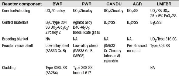
Table 16.4 shows major component materials used in different reactor systems.
Table 16.4 Major Component Materials Used in Different Reactor Systems
16.6.1 Pressurized Water Reactor
A pressurized water reactor (PWR) power plant is composed of two loops in series as shown in Figure 16.16. One is the coolant loop called primary loop and the other is the water steam or working fluid loop.
Referring to Figure 16.17, hot water from the reactor flows to a steam generator where heat is transferred to water and steam in the secondary cooling system, which operates at a lower pressure. The primary coolant then flows from the steam generator to the primary cooling pump, where it is pumped back to the reactor. The pressurizer is a pressure vessel with a heater at the bottom and a water spray at the top. The top of the pressurizer is filled with steam at primary system pressure (15.5 MPa). If the primary loop pressure drops, the heater is energized to increase the steam content in the pressurizer and thus increases the pressure of primary cooling system. If the primary system pressure is too high; cold pressurized water is sprayed into the steam, condensing the steam and hence reducing the primary system pressure.

Fig. 16.16 A PWR Power Plant

Fig. 16.17 Schematic of a PWR Power Plant
Advantages
- Due to high negative temperature coefficient, a PWR is safe and stable in operation and regulation.
- Control rods need not be used for load change except only during start-up and slow-down reactions.
- It has a positive power demand coefficient (due to negative temperature coefficient) and responds greatly to more power demand.
- Uses enriched fuel making the reactor more compact in size.
- It provides complete freedom to inspect and maintain the turbine, feed heaters and condenses during operation.
- Water, which is used as a coolant, moderator and reflector is cheap in first cost and available in plenty.
- It reduces the fuel cost by extracting more energy per unit weight of fuel.
- A PWR is ideally suited to the utilization of fuel designed for higher burn-ups.
Disadvantages
- High primary circuit pressure requires a strong pressure vessel with subsequent high capital cost.
- Due to low pressure in the secondary circuit (60–70 bar), thermodynamic efficiency is lower (20 per cent).
- Reprocessing of fuel is difficult as it suffers radiation damage.
- Presence of high temperature, high-pressure water and corrosion is severe. This means use of stainless steel for vessel and cladding, which further adds to plant cost.
- When γ-radiations pass through the pressure vessel, it results in uneven heating, which induces thermal stresses on the vessel.
16.6.2 Boiling Water Reactor (BWR)
In the BWR, the coolant is in direct contact with the heat-producing nuclear fuel and boils in the same compartment in which the fuel is located. The reactor pressure is maintained at 70 bar. As water and vapour coexist in the core, a BWR produces saturated steam at about 285°C. This operating temperature gives a Carnot efficiency of only 42 per cent with a practical operating efficiency of around 32 per cent lesser than the PWR. The coolant thus serves the triple function of coolant, moderator and working fluid. The disadvantage of this reactor is that any fuel leak might make the water radioactive and the radioactivity would reach the turbine and the rest of the loop in all probability (Figure 16.18).

Fig. 16.18 A BWR Power Plant
A BWR power plant consists of a reactor, a turbine generator, a condenser and air ejector, a cooling system, etc.
Slightly sub-cooled liquid enters the reactor core at the bottom receiving sensible heat to saturation and some latent heat of vapourization. When it reaches the top of the core, it is converted into a very wet mixture of liquid and vapour. The vapour separates from the liquid, flows to turbine, does work, condenses in the condenser and is then pumped back to the reactor by feed pump.
The saturated liquid separating from the vapour at the top of the reactor (steam separator) flows downwards through the down comer either internally (Figure 16.19(a)) within the reactor or externally (Figure 16.19(b)) outside the reactor and mixes with the return condensate. The flow through the down comer may be either natural or by means of a recirculating pump. The ratio of recirculation liquid to the saturated vapour produced is called recirculation ratio. It ranges between 6 and 10.

Fig. 16.19(a) Internal Recirculation of BWR

Fig. 16.19(b) External Circulation of BWR
16.6.2.1 Boiling Water Reactor Cycles
Three different BWR cycles commonly used are as follows:
1. Single-cycle internal circulation
This system shown in Figure 16.20 uses internal recirculation system to generate power ranging from 50 to 100 MW.

Fig. 16.20 Single-Cycle Circulation
2. Single-cycle forced circulation
This type shown in Figure 16.21 uses a forced circulation system using a circulating pump. The heat in the reactor is used to generate steam. It is useful to generate power ranging from 100 to 1000 MW.

Fig. 16.21 Forced Circulation (External)
3. Dual-cycle forced circulation
This arrangement shown in Figure 16.22 has two cycles: steam and gas.
Advantages
- The reactor vessel is much lighter compared to a PWR as pressure inside the reactor vessel is considerably smaller than the PWR. This means cost of pressure vessel is less.
- The reactor does not require steam generator, pressurizer circulating pump and connecting piping. This reduces the plant cost further.
- Since boiling is allowed inside the reactor, the metal surface temperature is lower than PWR.

Fig. 16.22 Dual-Cycle Forced Circulation
- Thermal efficiency of this reactor plant is considerably higher than PWR plant.
- BWR is more stable than PWR and much stable than any other type of reactor. It is also called as self-controlled reactor.
Disadvantages
- Light shielding of turbine and piping is necessary. Steam leaving the reactor is slightly radioactive.
- The size of the vessel will be considerably less compared to PWR.
- The possibility of ‘burn out’ of fuel is more in this reactor than PWR as boiling of water on the surface of fuel is allowed.
- If it is not properly designed, the BWR might have negative power demand coefficient; when more power is demanded from reactor it may produce less.
16.6.3 CANDU Heavy Water Reactor
Heavy water composed of heavy hydrogen isotope 2H is used as a moderator and coolant in some power and research reactors. These reactors use heavy water as moderator and primary coolant and light water as secondary coolant. The Canadians have exported such reactors known as CANDU reactors.
The CANDU reactor (Figure 16.23) consists of a primary loop and a secondary loop. Fuel is burnt in the reactor releasing heat energy so that the primary coolant (heavy water) coming in contact with the reactor core gets heated up. The heated primary coolant is taken to the steam generator boilers where it gives the heat energy to the light water condensate. Steam is generated due to heat transfer and is used for power generation. The pressurizer maintains constant pressure of the primary loop system. Due to condensation, if the primary line pressure falls below the rated pressure, the heater gets activated heating the heavy water and thus increasing the line pressure due to formation of vapour. The primary coolant is pumped back to the reactor core using primary pumps. A separate system of heavy water is used as a moderator to reduce the energy of fast neutrons to thermal neutrons.
Figure 16.24 shows how the steam from the collectors are further fed to the HP and LP turbines to generate power.

Fig. 16.23 CANDU Reactor

Fig. 16.24 Simplified Steam Cycle of CANDU Reactor
Figure 16.25 shows fuel assembly of a pressurized heavy-water reactor (PHWR-CANDU). The main structural materials used are zirconium and aluminum alloys. The use of heavy water as a moderator provides good neutron economy and permits a wide range of possible fuel cycles (including Th, 233U or U, Pu) and fuel management schemes. The UO2 fuel elements are placed in Zircaloy-2 pressure tubes, which pass through an aluminum calandria containing the heavy water moderator another form of CANDU reactor working on the same principle.

Fig. 16.25 Fuel Bundle for CANDU Reactor [1]
Note: (1) Zircaloy structural end plate; (2) Zircaloy end cap; (3) Zircaloy bearing pads; (4) VO2 pellets; (5) Zircaloy fuel sheath; (6) Zircaloy spacers; and (7) graphite coating
Advantages
- The fuel need not be enriched.
- No control rods are required; therefore, control is much easier than other types of reactors.
- Fuel tubes are designed to withstand high pressure, therefore cost of the vessel is less.
- Moderator will be kept at low temperature, which increases its effectiveness to slow down neutrons.
- This type of reactor has low fuel consumption and higher multiplication factor.
- Time required for site construction will be less compared to PWR and BWR.
Disadvantages
- Loss of heavy water is high.
- Leakage is a major problem as there are two mechanically sealed closure per fuel channel.
- Compared to PWR and BWR power density is considerably low; therefore, the reactor size is extremely large.
- Very high standard of design, manufacture, inspection and maintenance are required.
16.6.4 Gas-Cooled Reactor
Gas-cooled reactors, namely Magnox and AGR belong to very earliest reactor designs in that they are graphite moderated and gas cooled. The early gas-cooled reactors popularly known as Magnox reactors (Figure 16.26) were built in the UK during 1956–1971, but have now been superseded. This reactor used the magnesium alloy to encase the fuel (natural uranium) and hence named after this. Fuel elements consisting of fuel rods encased in Magnox cans. These in turn are loaded into vertical channels in a core constructed of graphite blocks. To adjust the rate of the fission process and the heat output, control rods (strong neutron absorbers) in the vertical channels are either inserted or withdrawn from the core. The whole assembly is cooled by blowing carbon dioxide gas past the fuel cans, which are specially designed to enhance heat transfer. The hot gas converts water to steam in a steam generator. Although the early designs used a steel pressure vessel, which was surrounded by a thick concrete radiation shield, the later designs were constructed with a dual-purpose concrete pressure vessel with a radiation shield.

Fig. 16.26 Gas-Cooled Reactor (Magnox)
To improve cost effectiveness, higher thermal efficiencies and higher power densities, these reactors were modified to operate at higher temperatures. This system used higher cooling gas pressure and stainless steel cladding with uranium dioxide fuel. This reactor is known as the Advanced Gas-Cooled Reactor, or AGR, and uses graphite as the moderator. As shown in Figure 16.27, the steam generators and gas circulators are placed within a combined concrete pressure-vessel/radiation-shield.

Fig. 16.27 Gas-Cooled Reactor (AGR)
16.6.5 Fast Breeder Reactors
If the reactor produces more fissionable material than it consumes, it is called a breeder reactor. Breeder fuel consists of both fertile and fissile materials. The number of neutrons released is sufficient to propagate the fission reaction and to produce more fissionable material by conversion of fertile isotopes to fissile isotopes. No moderator is used in the breeder reactor since fast neutrons are more efficient in transmuting U-238 to Pu-239.
The Pu-239 breeder reactor is commonly called a fast breeder reactor, and the cooling and heat transfer are done by a liquid metal. The metals used for this purpose are sodium and lithium. As sodium is most abundantly available it is most commonly used. The construction of the fast breeder requires 15–30 per cent higher enrichment of U-235 than a light-water reactor. The reactor fuel is surrounded by a ‘blanket’ of non-fissionable U-238. At this concentration of U-235, the cross-section for fission with fast neutrons is sufficient to sustain the chain reaction.
The two most commonly used breeding cycles are
- conversion of fertile U238 to fissile Pu239
- conversion of fertile Th232 to fissile U233
Since uranium cycle uses high-energy neutrons, it is called as fast breeder reactor. These reactors use liquid sodium metal or pressurized helium as a coolant and no moderator to slow down the neutrons.
The following three types of fast breeder reactors are in use:
- Liquid metal fast breeder reactor (LMFBR)
- Gas-cooled fast breeder reactor (GCFBR)
- Molten salt breeder reactor (MSBR)
16.6.5.1 Liquid Metal Fast Breeder Reactor (LMFBR)
The fuel consists of 80 per cent by weight of UO2 and 20 per cent by weight of PuO2 in small diameter stainless steel-clad tubes operating at temperatures of 670–700°C. The coolant used is sodium, which is a solid at room temperature but liquefies at 98°C. It has a wide working temperature since it does not boil until 892°C. The range of operating temperatures for the reactor falls within this so that it does not need to be pressurized as in a water–steam coolant system. It has large specific heat and hence efficiently transfers heat. Fuel assemblies and clusters of fuel pins are immersed in liquid sodium coolant flowing at low pressure through the reactor, entering the reactor core at 400°C and leaving at 620°C. Since primary sodium becomes intensely radioactive in the reactor, a secondary nonradioactive sodium coolant loop is used (Figure 16.28).

Fig. 16.28 Liquid Metal-Cooled FBR
The primary loop of the system may be either pool type (Figure 16.29) or loop type (Figure 16.30). In the pool-type system, the entire primary system, namely the reactor, primary heat exchangers, pumps are submerged in a large tank filled with molten sodium. The coolant is directly discharged from the heat exchanger to the tank and pumped from there further. This system is relatively insensitive to sodium leakage in the primary system, and compact also. However, the system is rather complex as the pool enclosure includes shield, inert gas closure, etc.
In the loop-type system, the heat exchangers, liquid metal pumps and other components of the primary system and the interconnecting piping arrangements are separated within a large building filled with an inert gas to prevent fire hazard from sodium leakage.
Advantages of using a liquid metal are
- excellent heat transfer
- low-absorption cross section

Fig. 16.29 Pool Type

Fig. 16.30 Loop Type
- low melting point
- high BP
- highly specific
- high thermal conductivity
- (vii) cheap
Advantages
- High temperature can be achieved in the cycle, therefore thermal efficiency is high.
- Low-cost graphite moderator can be used as it can retain its mechanical strength and purity at high temperatures.
- Sodium as a coolant need not be pressurized.
- The reactor size is comparatively small.
- It is best suited to thermal reactor with slightly enriched fuel.
Disadvantages
- Leak of sodium is very dangerous as it comes out of reactor in a highly radioactive state.
- Care must be taken to see that sodium does not come in contact with water as it becomes highly radioactive forming caustic soda with evolution of heat.
- It is necessary to shield the primary and secondary cooling systems.
- It is always necessary to keep the graphite and sodium separate.
16.6.5.2 Gas-Cooled Fast Breeder Reactor (GCFBR)
The GCFBR (Figure 16.31) is cooled by helium gas at 85 bar. Also, helium does not become radioactive under neutron bombardment and hence secondary coolant is not needed.

Fig. 16.31 Gas-Cooled Reactor
Advantages of using helium are as follows
- Using helium as a coolant poses less severe metallurgical and safety problems.
- Helium is chemically inert, does not become radioactive and does not degrade the neutron spectrum. This leads to high conversion factor and negligible void reactivity coefficient.
- Heat transfer coefficient of helium is much superior than sodium with artificial roughening of fuel rod surfaces.
- Low doubling time (10–12 years) as compared to sodium-cooled reactors (20 years).
Disadvantages
- (i) Reactor vessel needs to be pressurized to 70–80 bar.
Advantages
- Fuel processing is simple, as cladding problem of metallic fuel does not exist.
- As uranium carbide and graphite can withstand high temperatures, limiting the fuel element temperature is not as serious as in other reactors.
- Possibility of explosion in the reactor is avoided due to the use of CO2 as coolant, which is a major problem in water-cooled plants.
- Corrosion problem is eliminated.
- Due to low parasitic absorption, neutron economy is better.
- Graphite remains stable under irradiation at high temperatures.
Disadvantages
- Large vessel is required as power density is very low due to low heat transfer coefficient.
- Leakage of gas is a major problem if helium is used instead of CO2.
- Loading of fuel is very elaborate and costly.
16.6.6 Organic Substance Cooled Reactor
Figure 16.32 shows an organic substance cooled reactor used in Piqua city, Ohio, USA. It uses enriched uranium as fuel and a mixture of orthometaterhenyl and paratherphenyl as coolant and moderator, and boron control rods, generating 11.4 MW capacity with an overall efficiency of 25 per cent.

Fig. 16.32 Organic Cooled and Moderated Reactor
Advantages of using organic substance are
- Core operates at relatively high temperature at moderate pressure.
- Less corrosive, hence low carbon steel can be used for piping. This makes low initial cost.
- Steam does not become radioactive.
- Do not freeze at low temperature.
Disadvantages
- Decompose when exposed to neutron, γ-radiation, leaving slurry deposits on fuel can surfaces reducing heat transfer.
- Poor heat transfer properties as compared to water.
- Highly inflammable.
Advantages
- Compact core design is possible as organic liquid is used as both coolant and moderator.
- Core operating pressure is low due to high temperature at low vapour pressure.
- A wide variety of fuels as uranium, uranium alloy, oxide or uranium carbide can be used with organic coolants due to their excellent moderating properties.
- Low carbon steel can be used for vessel and piping as organic fluid does not corrode the tubes. This reduces initial capital cost.
Table 16.5 shows the summary of different types of thermal reactors.
Table 16.5 Summary of Different Types of Thermal Reactors

As per the data released by the European nuclear society (Table 16.6), mainly PWRs are used in the nuclear power plants worldwide – 62 per cent according to the number, 68 percent according to the output – followed by BWR – 19 per cent according to the number, 21 per cent according to the output.
Table 16.6 Nuclear Power Plants, Worldwide, Reactor Types, 18 January 2013

16.7 REACTOR CONTROL
Reactor power control is accomplished by using control rods and burnable poisons that contain neutron-absorbing materials. In PWRs, boric acid, a soluble chemical, in the primary coolant, also provides power control. By varying the concentration of boric acid is varied to control reactivity changes caused by depletion of fuel and build-up of fission products.
1. Boron carbide
Boron carbide is the most extensively used control material. It is used in thermal and fast reactors. The absorption of neutrons by 10B results in the primary formation of 7Li, helium and tritium as given by the following reactions:
B + n → He + Li + 2.3 MeV
B + n → T + He + He
The fast neutron capture cross section of the 10B isotope is greater than that of any other known isotope.
2. Silver-base alloys
An alloy of silver combined with 15 wt per cent cadmium and 5 wt per cent indium is used for control rod with suitable neutron-absorption properties over a wide range of neutron energies present in pressurized light-water reactors. This alloy clad in stainless steel or Inconel has been used as control rod material in PWRs.
3. Hafnium
Hafnium can be used to control the LWRs without excessive reactivity loss or damage over extended irradiation (approximately 40 year) for the lifetimes of the plants.
4. Europium hexaboride
There has been increasing interest in the use of europium hexaboride as an alternate control material to B4C in fast breeder reactors.
5. Europium oxide
Europium oxide is another material being considered as a neutron absorber material for use in the control rods. Many fast breeder reactors in the United States, Britain, Germany and Russia have tested Europium oxide. The BOR-60 fast breeder reactor (Russia) has operated satisfactorily since 1972 with europium oxide in one of the control rods.
6. Burnable poisons
Neutron-absorbing materials are also used in reactors to prevent power peaking in the early stages of operation of the core. They allow optimum burn-up of the fuel and power shaping in the core. PWRs use boric acid solution in the primary coolant as burnable poison to provide power control. Ceramic pellets containing burnable poisons are included in the fuel rods in most power reactors. Examples of these materials are boron carbide dispersions in alumina, gadolinium oxide dispersed in the uranium dioxide fuel and borosilicate glass.
16.8 RADIATION HAZARDS
Effects of nuclear radiation
Biological damage by interaction of radiation and tissue:
- Ionization – λ, β, γ – radiations ionize tissues into which they penetrate, resulting in complete damage of tissue.
- Displacement – atom in the tissue is displaced by neutron and γ-radiation.
- Absorption – Absorption of neutron by a tissue nucleus leads to radioactive nucleus, which results in change in chemical nature, malfunctioning of cell. Due to this, cell gets damaged leading to genetic modification.
Inhalation of radioactive material through air, food and water results in radiation hazard.
16.8.1 Handling of Nuclear Waste and Safety Measures
Wastes associated with nuclear power are as follows:
1. Gaseous effluents
Under normal operation, these are released slowly from the power plants into the biosphere and become diluted and dispersed harmlessly.
2. Uranium mine and mill tailings
Tailings are residues from uranium mining and milling operations. They contain low concentration of naturally occurring radioactive materials. They are generated in large volumes and are stored at the mines or mill sites.
3. Low-level wastes
Low-level waste (LLW) includes items that have become contaminated with radioactive material or have become radioactive through exposure to neutron radiation. This waste typically consists of contaminated protective shoe covers and clothing, wiping rags, mops, filters, reactor water treatment residues, equipments and tools, luminous dials, medical tubes, swabs, injection needles, syringes, and laboratory animal carcasses and tissues, etc. These contain less than 10 nCi per gram of trans-uranium contaminants containing low but potentially hazardous concentrations of radioactive materials. These are generated in almost all activities (power generation, medical, industrial, etc) involving radioactive materials, require little or no shielding. These are disposed off in liquid form by shallow land burial.
4. High-level wastes
High-level wastes (HLW) are generated in reprocessing of spent fuel. They contain all fission products and contain most of the trans-uranium elements not separated during reprocessing. Such wastes are to be disposed off carefully. Since the only way radioactive waste finally becomes harmless is through decay, which for HLW can take hundreds of thousands of years, the wastes must be stored and finally disposed off in such a way that provides adequate protection to the public.
5. Spent fuel
This is unprocessed spent fuel that is removed from the reactor core after reaching its end- of-life core service. It is removed and then stored for three to four months under water in the plant site to give time for the most intense radioactive isotopes to decay before shipment for reprocessing or disposal.
Note: Units of nuclear radiation – Roentgen – amount of radiation that will on passing through pure air under standard condition produce 1 electrostatic unit of ions/cm3 of air ⇒ 86.9 ergs of energy absorbed/g of air, Rem – dose of absorbed radiation that will have the same effect that exposure to 1 Roentgen of γ-radiation will have ⇒ 100 ergs/g of tissue, total dose driving a person's life time < 200 Rem weekly dose < 0.3 Rem.
Figure 16.33 shows a typical fuel cycle generating these wastes.

Fig. 16.33 A Typical Fuel Cycle
16.8.2 Radioactive Waste Disposal
One of the major problems in the nuclear plants is the disposal of waste products that are highly radioactive. They emit large quantities of γ rays and these high-energy γ rays destroy all living matter through which they pass.
The radioactive products of 400 MW power station would be equivalent to 100 tons of radium daily and the radioactive effect of these plant products if exposed to atmosphere would kill all the living organisms within an area about 100 square miles.
The disposal of nuclear waste is a very difficult problem for the engineers and scientists.
In a nuclear fuel cycle, the solid, liquid and gaseous radioactive wastes are produced at different stages. These radioactive wastes must be disposed off in such a manner that there is no hazard to human and plant life. Moderate active solid wastes are buried in the ground. Moderate liquid wastes after preliminary treatments are discharged in deep pits or dry wells to keep them from seeping out into the surrounding ground. Active liquids are kept in concrete tanks and these tanks are buried in the ground till the radioactivity decays. Many times the radioactivity increases the temperature of the liquid waste or sometimes these liquids boil and the activity decreases with time. Gaseous wastes are discharged to atmosphere through high stacks if the wind permits.
The waste is disposed to air, ground and ocean.
1. Air
There are a lot of issues in the disposal of radioactive gases into the air. Because strong radioactive gases such as strontium and iodine are absorbed by the plants and they enter into the human body through food. Caesium is absorbed in muscle and strontium is absorbed in bones resulting in paralyses of the body. Generally, radioactive gases are collected and stored in a tank buried in the ground and disposed off to the atmosphere when radioactivity level is sufficiently low.
The amount of radioactivity presently disposed off in the air is well below the harmful level, but the problem will become serious when a large number of power reactors come up in operation.
2. Ground
This is one of the easy and cheapest methods of disposal because soil absorbs radioactive material easily. This disposal is suitable mostly in areas of low rainfall that are high above the ground water level.
Most of the radioactivities of waste are removed just by storage. The storage problem is simplified by separating caesium and strontium, which are extremely radioactive. These are generally stored in tanks that are buried in ground and then disposed off into the sea after 13 years of storage.
Defunct coal mines are used for waste disposal. The wastes are disposed off in salt heaps provided in the mines, because salt is a powerful absorber of radioactive emissions. Disposing off liquid waste by freezing is an easy and more economical method.
Disposal of LLW: The final deposition of the wastes is a major concern. Many countries are undertaking activities involving underground disposal in deep geological formations. These countries are investigating suitable sites and suitable methods of storage at these sites. These methods must be efficient enough to protect present and future populations from potential hazards. The suitable sites must be free of flowing ground water, but storage vessels must demonstrate reliability even in flowing water conditions.
The disposal of low and intermediate level wastes is done at relatively shallow depths in many countries, namely packing the waste in solid form in concrete steel drums and burying (Figure 16.34).

Fig. 16.34 Disposal of LLW
If spent fuel is to be disposed, it is buried in the earth, namely deep salt or granite formations below ground or below the sea bed.
Figure 16.35 shows a conceptual depository for the storage of HLW in rock salt formation for thousands of years. The solidified waste is placed in canisters that are stored in holes drilled in rock salt with a spacing of 10 m to allow efficient dissipation of energy without exceeding the temperature limits of either canister or salt. Each canister requires 100 m2 of salt for cooling.

Fig. 16.35 Canister for Vitrified High-Level Waste
3. Ocean
In many places, the liquid waste is disposed off to the sea through the pipes carried from the plant to the point of disposal. While disposing off the waste into the sea, it should be ensured that the radioactivity level should not be very harmful to the fish life and seaweed, which is harvested for human use. In another method, the solid wastes should be cased into concrete blocks and these should be dropped into the sea at suitable places. The cost of disposal by this method is approximately ₹ 300 per cubic metre volume.
The danger of disposal into the sea water is indirect and depends on the absorption of radioactive elements such as caesium and strontium by plankton and then through the biological chain to the edible fishes and then to humans.
It is necessary to keep the radioactive solid waste at a depth of 6 m in water nearly for 100 days. It was found that after 100 days cooling of radioactive waste of 28 MW plant in water still had a radioactivity equal to million grams of radium. About 50 per cent of the radioactive elements disappear during cooling.
16.8.2.1 Different Methods for Nuclear Waste Disposal
In this section, different types of nuclear wastes and the methods used to handle them are discussed. These are as follows:
- Fission fragments → weak, intensity active; isotopes → spent fuel stored under 6 m deep water to cool (100 days) → intensely active
- Radioactive waste – gaseous liquid, solid
Solid → buried at depths of few metres
Gaseous → discharged to atmosphere through high stacks
Liquid → after preliminary treatment discharged in dry wells or deep pits
- Waste solution → stored in a stainless steel tank enclosed in a concrete wall, buried under earth (10 m) and provided with cooling oil to keep temperature at 50°C
- Low-level solid waste → cast in cement in steel drum → drums buried below soil or kept at the bed of ocean
- Medium-level solid waste → incorporated into cement cylinders
- 6. High-level liquid waste → stored in special steel tanks in concrete walls, water cooled → taken to storage area and disposed within 10 cm thick lead wall surrounded by 6 mm titanium.
Some other locations and methods used for nuclear waste disposal are as follows:
(i) Geological formations
- Rock salt
- Powerful absorber of radioactive emission
- Good thermal conductivity
- Cavities and tunnels can be easily made
- Argillaceous sediments – boreholes are provided at 160–260 m depths in a 100-m thick bed of clay
- Hard rocks – igneous, metamorphic, sedimentary rocks
(ii) Ocean
Floors of deep ocean provide safe, potential disposal sites for solidified high-level radioactive waste
(iii) New methods to treat HLW
- HARVEST Process – (highly active residues vitrification engineering study). This process was developed in 1970. In this process, highly active liquid waste is mixed with glass forming chemical in a steel container. The container is heated in a furnace to about 1000°C. It involves the following process. This mixture fuses to glass, which is further cooled, sealed and then discharged to the storage area (Figure 16.36).
Liquid waste + glass-forming material → heated steel vessel
↓
Mixture fuses to glass
↓
Cooled, sealed, discharged to storage

Fig. 16.36 Waste Treatment (HARVEST Process)
- AVM (Atelier de Vitrification Marcoule) Process
Figure 16.37 shows AVM (Altier de –Vitrification Marcoule) process used for liquid waste disposal. The process is self-explanatory. In this process, the liquid waste fed to a container is heated in a furnace and further mixed with glass powder. The mixture that comes out is melted in a melting furnace and collected in a vessel. In the subsequent steps, the container is closed and the exterior body of the vessel is decontaminated before disposing off into the storage area.

Fig. 16.37 AVM Process
(iv) Nuclear waste calcining
Liquid → solid means small volume and easy storage. Calcining the liquid waste results in free flowing non-corrosion granules.
Features
- Spent fuel is reduced to a liquid
- Extraction of usable fuel from liquid
- Calcining the liquid waste
Off-gas clean-up system
Figure 16.38 shows an off-gas clean up system. Hot gas is quenched and passed through scrubbers and dried in condensers, demisters. It is then reheated and passed through silica gel absorber, demisters, filters, atmosphere protection system and then discharged to atmosphere through a stack 80 m high.

Fig. 16.38 Off-Gas Clean-Up System
Gas disposal system – krypton, iodine gases, tritium, CO2
Crypton – cryogenic treatment of dissolved off-gas stream, packed in gas cylinder under pressure
Iodine – caustic scrubbing or HNO3 scrubbing
Tritium – voloxidetion, pyrochemical processing, isotope enrichment
CO2 – Caustic scrubbing
Rupture in the fuel element cladding releases gaseous fission products.
16.9 NUCLEAR POWER GENERATION IN INDIA
As per the information available in the Nuclear Power Corporation of India (NPCIL) (http://www.npcil.nic.in), nuclear power generation (starting from the year 2006–2007 till June 2013) from the operational plants in million units are given in Table 16.5.
Table 16.5 Nuclear Power Generation (2006–2007 to 2013–2014)

Most of the power plants commissioned in India are of pressurized heavy water reactor type except unit-1 and unit-2 of Tarapur Atomic Power Station (TAPS), Maharashtra. These plants use natural uranium fuel and heavy water as coolant and moderator. At the ground level, India's nuclear power programme has 20 reactors with an installed capacity of 4800 MW. Kudankulam 1 will add 1000 MW.
But the NPCIL has ambitious plans. Four indigenous Pressurized Heavy Water Reactors (PHWRs) of 700 MW totalling 2800 MW are being constructed by the NPCIL in other parts of the country; they are expected to be commissioned by 2016–2017.
A further 10 of the same size are planned, which means domestic reactors of nearly 10,000 MW capacity are in the pipeline. Some of them will be in new locations such as Gorakhpur in Haryana, Mahi Banswara in Rajasthan and Chutka and Bhimpur in Madhya Pradesh. All these efforts demand a huge requirement of natural uranium.
Table 16.6 shows the Total Nuclear Power Plant Capacity of India to 4780 MW
Table 16.6 Nuclear Power Plants of India (as on January 2011)

16.10 QUESTIONS
16.10.1 Objective Questions
- The efficiency of a nuclear power plant in comparison to a conventional thermal power plant is
- same
- more
- less
- maybe less or more depending on size
- Isotopes of same elements have
- same atomic number and different masses
- same chemical properties but different atomic numbers
- different masses and different atomic numbers
- different chemical properties and same atomic numbers
- The mass number of a substance represents the sum of total number of
- protons and neutrons in an atom
- protons and electrons in an atom
- neutrons and electrons in an atom
- protons and neutrons in a nucleus
- Amongst the following, the fissionable materials are
- U233 and Pu239
- U231 and Pu233
- U235 and Pu235
- U238 and Pu239
- A nuclear unit becoming critical means
- it is generating power to rated capacity
- it is capable of generating much more than rated capacity
- there is danger of nuclear spread
- chain reaction that causes automatic splitting of the fuel nuclei has been established
- Moderator in nuclear plants is used to
- reduce temperature
- extract heat from nuclear reaction
- control the reaction
- cause collision with the fast moving neutrons to reduce their speed
- The most commonly used moderator in nuclear plants is
- heavy water
- concrete and bricks
- graphite and concrete
- graphite
- Breeder reactor has a conversion ratio of
- unity
- more than unity
- less than unity
- zero
- Fast breeder reactor uses
- boiler
- direct cycle of coolant system
- double circuit system of coolant cycle
- multi-pass system
- One gram of uranium will produce energy equivalent to approximately
- 1 tonne of high-grade coal
- 4.5 tonnes of high-grade coal
- 10 tonnes of high-grade coal
- 100 tonnes of high-grade coal
- Which of the following nuclear reactor does not need a heat exchanger for generation of steam?
- gas cooled
- liquid metal cooled
- pressurized water
- boiling water
- The commonly used material for shielding is
- lead or concrete
- lead and tin
- graphite or cadmium
- thick galvanized sheets
- The main interest of shielding in nuclear reactor is protection against
- X-rays
- infrared rays
- a, P and y rays
- neutrons and gamma rays
- Reflector in nuclear plants is used to
- return the neutrons back into the core
- shield the radioactivity completely
- check pollution
- conserve energy
- The energy required to be applied to a radioactive nucleus for the emission of a neutron is
- 1 MeV
- 2.4 MeV
- 4.3 MeV
- 7.8 MeV
- Ferrite material is
- the most fissionable material
- the basic fuel for nuclear paints
- the basic raw material for nuclear plants
- the material that absorbs neutrons and undergoes spontaneous changes leading to the formation of fissionable material
- Enriched uranium is one in which
- percentage of U235 has been artificially increased
- percentage of U has been artificially increased
- percentage of U234 has been artificially increased
- extra energy is pumped from outside
- 18. In fast breeder reactors
- any type of moderator can be used
- graphite is used as the moderator
- heavy water is used as the moderator
- moderator is dispensed with
- In nuclear fission each neutron that causes fission releases
- no new neutron
- at least one new neutron
- one new neutron
- more than one new neutron
- The breeding gain in case of thermal breeder reactor as compared to fast breeder reactor is
- same
- lower
- higher
- higher/lower depending on the size of reactor
- Gas-cooled reactor uses the following materials as moderator and coolant
- graphite, CO2
- graphite, air
- heavy water, CO2
- lead, H2
- A nuclear fission produces energy of following order in MeV
- 20
- 200
- 2000
- 20,000
- The process by which a heavy nucleus is split into two light nuclei is known as
- splitting
- fission
- fusion
- chain reaction
- The first unclear power plant in India is located at
- Kota
- Kalapakkam
- Tarapur
- Baraeilly
- Boiling water reactor uses the following as moderator, coolant and working fluid
- ordinary fluid
- heavy water
- molten lead
- hydrogen gas
- U235 will undergo fission by
- High energy (fast) neutrons alone
- Low energy (slow) neutrons alone
- Either fast or slow neutrons
- Medium energy neutrons
- U238 will undergo fission by
- High energy (fast) neutrons alone
- Low energy (slow) neutrons alone
- Either fast or slow neutrons
- Medium energy neutrons
- A reactor capable of converting a ferrite material into fissile isotopes is called
- Regenerative reactor
- Fast breeder reactor
- Breeder reactor
- Boiling water reactor
- Hydrogen is preferred as better coolant in comparison to CO2 because former
- Is lighter
- Is inert
- Has high specific heat
- Is a good conductor
- Natural uranium is made up of
- 99.282% U238, 0.712% U235, 0.006% U234
- 99.282% U235, 0.712% U238, 0.06% U234
- 99.282% U234, 0.712% U238, 0.006% U235
- 99.282% U235, 0.712% U234, 0.006% U238
- Pick up the wrong statement Fast breeder reactors
- Operate at extremely high power densities.
- Are liquid-metal cooled
- Produce more fuel than they consume
- Use water as coolant.
- A pressurized water reactor employs pressurizer for the following application
- To maintain constant pressure in primary circuit under varying load
- To Supply high pressure steam
- To increase pressure of water in primary circuit
- To provide subcooled water at high pressure
- The function of control rods in nuclear plants is to
- Control temperature
- Control radioactive pollution
- Control absorption of neutron
- Control fuel consumption
- Breeder reactors employ liquid metal coolant because it
- Acts as good moderator
- Produces maximum steam
- Transfers heat from core at a fast rate
- Breeds neutrons
- In triggering fission, which type of neutrons are more effective
- Fast
- Slow
- In bulk
- Static
- A fission chain reaction in uranium can be developed by
- Slowing down fast neutrons so that Uz fission continues by slow motion neutrons
- Accelerating fast neutrons
- Absorbing all neutrons
- Using moderator
- In triggering fission, the following types of neutrons are desirable
- Fast moving
- Slow moving
- Critical neutrons
- Neutrons at rest
- Each fission of U235 produces following number of fast neutrons per fission
- 1 neutron
- 1 neutrons
- 1 2 neutrons
- 2 neutrons
- A boiling water reactor uses following as fuel
- Enriched uranium
- Plutonium
- Thorium
- U
- A fast breeder reactor
- Uses graphite rods as moderator
- Has powerful moderator
- Has no moderator
- Uses ferrite material as moderator
- A fast breeder reactor uses
- 90% U-235
- U-238
- U-235
- Pu-239
- The coolant used in boiling water reactor is
- CO2
- Pressurized water
- Mixture of water and steam
- Liquid metal
- In boiling water reactor, moderator is
- Coolant itself
- Ferrite rod
- Graphite rod
- Liquid sodium metal
- The efficiency of a nuclear power plant in comparison to conventional and nuclear consideration is
- Higher cost of nuclear fuel
- High initial cost
- High heat rejection in condenser
- Lower temperature and pressure conditions
- The fuel needed, with reflector in nuclear power
- More
- Less
- Same
- Zero
Answers
- c 2. b 3. d 4. a 5. d 6. d 7. d 8. b 9. c 10. b 11. d 12. a 13. d 14. a 15. d 16. d 17. a 18. d 19. d 20. b 21. a 22. b 23. b 24. c 25. a 26. c 27. a 28. a 29. c 30. a 31. d 32. a 33. c 34. c 35. b 36. a 37. b 38. d 39. a 40. c 41. a 42. c 43. a 44. d 45. b
16.10.2 Review Questions
- Give the classification of nuclear reactors.
- Explain the factors that control the site selection of nuclear power plant.
- Sketch and explain liquid metal cooled reactor and also list its merits.
- Write short notes on nuclear waste disposal.
- Explain with a sketch the elements of a nuclear reactor.
- Describe the working of sodium graphite reactor with a neat sketch.
- Write short notes on fusion and fission reactions.
- Make a neat sketch and explain the working of a gas cooled reactor.
- Explain the phenomenon of chain reaction and the difficulties encountered with and the methods adopted for disposal of the different wastes in nuclear power plants.
- What are the various factors to be considered while selecting the site for nuclear reactor?
- What do you understand by terms binding energy and mass defect? How they are related to each other?
- What are the different types of nuclear reactions taking place? Explain the significance of each in nuclear power generation.
- What do you understand by nuclear fission? What are the essential requirements to cause nuclear fission?
- What is chain reaction? How it is maintained?
- What is the difference between controlled and uncontrolled chain reaction? Explain with neat sketches and with examples.
- What different moderators are used in practice? What different properties make them suitable moderators?
- What do you understand by fertile material and breeding. What is the importance of breeding in power engineering?
- Draw a neat diagram of PWR and BWR and explain the advantages and disadvantages. What are the conditions which prefer PWR over BWR?
- Draw a neat diagram of CANDU type reactor and give its advantages and disadvantages of this reactor over other types.
- What are the outstanding features of advanced gas cooled reactors over other types?
- What factors control the selection of a particular type of reactor?
- What do you understand by breeding? What factors control the breeding?
- Draw a neat diagram of breeder reactor and list out its advantages and disadvantages. Why only sodium is used as a coolant in breeder reactors?
- Why the moderator is not required in breeder reactor?
- List out the advantages and disadvantages of nuclear plants over conventional thermal plants.
- What are the desirable properties of a good moderator?
- Why shielding of a reactor is necessary?
- What do you understand by thermal shielding?
- What are the desirable properties of a shielding material?
- Discuss the problems of health hazard from nuclear radiations.
- Explain how radioactive wastes are disposed off.
- Define multiplication factor and criticality.
- Give the advantages and disadvantages of thermal and fast reactors.
- 34. Discuss the merits and demerits of PWR in comparison to a gas cooled reactor.
16.10.3 Reference
- Simnad, M. T. and Howe, J. P., “Material Science in Energy Technology”, Academic Press, New York, 1979.