
12
Gas Turbine Power Plant
Contents
12.1 Introduction
12.2 Classification of gas turbines
12.3 Construction and plant layout with auxiliaries
12.4 Fuel and fuel systems
12.5 Gas turbine material
12.6 Advantages and disadvantages of the gas turbine plant
12.7 Method of improving output and performance
12.8 Free piston engine plant - limitation, application and advantages
12.9 Combined cycle power plants and comparison
12.10 Layout of gas turbine plant
12.11 Questions
12.1 INTRODUCTION
Gas turbine is a rotary machine that uses gas as a working fluid. The basic turbine consists of a compressor, a combustor or heater and a turbine or expander as shown in the Figure 12.1. The compressor is supplied with air at ambient conditions and raises its pressure and temperature to the required limit for combustion. The compressed air enters the combustor or combustion chamber where it gets heated from the fuel burning in the combustion chamber. The combustion products (gas and air) are then expanded in the turbine, thereby doing mechanical work. The gases are then exhausted to the atmosphere, as in an open-cycle gas turbine.

Fig. 12.1 Gas Turbine: Working Principle
12.1.1 Joule or Brayton Cycle
Simple gas turbines can be analysed using Joule or Brayton cycle. Some assumptions are made before making any attempt to analyse an ideal cycle. These assumptions are as follows:
- The effect of friction upon the machine and the fluid is neglected.
- The change in potential energy and kinetic energy of the medium as a result of overall process is neglected. Thus, pressure losses in the heat exchangers and the connecting passages are absent.
- There is no increase in the mass flow rate due to any addition of fuel.
- The working fluid is a perfect gas. The specific heat remains constant at all temperatures for turbines and compressors.
- Losses due to radiation are neglected.
Analysis of the cycle is carried out with the help of the above assumptions. The simple cycle with actual and ideal processes is shown in the p-V and T-s diagrams in Figure 12.2.

Fig. 12.2 Joule Cycle: Ideal and Actual Processes
12.1.1.1 Ideal Cycle Analysis
- 1–2′: Isentropic compression
Temperature increases from T1 to T2′
Pressure increases from p1 to p2.
Volume decreases from V1 to V2′.
Work done during the process,
WC = Cp (T2′ − T1) = h2′ − h1
Heat transfer is zero.
- 2′–3: Constant pressure heat addition
Temperature increases from T2′ to T3.
Pressure remains constant at p2′ = p3.
Volume increases from V2′ to V3.
Work done during the process
W2′ − 3 = p (V3 − V2′)
Heat transfer during the process,
QA = Cp (T3 − T2′) = h3 − h2′
- 3–4′: Isentropic expansion
Temperature decreases from T3 to T4.
Pressure decreases from p3 = p2 to p4′ = p1.
Volume increases from V3 to V4′.
Work done during the process,
WT = Cp (T3 − T4′) = h3 − h4′
Heat transfer is zero.
- 4′–1: Constant pressure heat rejection
Temperature decreases from T4′ to T1.
Pressure remains constant at p1 = p4
Volume decreases from V4′ to V1.
Work done during the process,
W4 − 1 = p(V4′ − V1)
Heat transfer during the process,
QR = Cp (T4′ − T1) = h4′ − h1
1. Net work done/cycle
Net work done by the cycle is the difference of the turbine work and the compressor work.
Net work done = turbine work − compressor work
![]() = heat added − heat rejected
= heat added − heat rejected
= QA − QR
= Cp (T3 − T2′) − Cp (T4′ − T1)
= Cp (T3 − T4′) − Cp (T2′ − T1)(1)
= (h3 − h4′) − (h2′ − h1)(2)
where, h = enthalpy of the working fluid, kJ/kg
2. Work ratio
Work ratio is defined as the ratio of net work done to the turbine work (positive work).
WR = ![]() =
= ![]()
= 
= 
WR =  (3)
(3)
Again, considering the isentropic processes 1–2′ and 3–4′:
WR = 
Let
 =
= ![]() =
= ![]() = R, say(4)
= R, say(4)
then,
WR = 
WR = ![]() (5)
(5)
3. Thermal efficiency
Thermal efficiency of the cycle is given by the ratio of net work done to the heat supplied.
η = ![]()
= ![]()
= 
= 
=  (6)
(6)
From the isentropic processes, 1–2′ and 3–4′,
R = ![]() =
= ![]() =
=  =
=  =
= 
where β = pressure ratio = ![]()
Equation (6) can be modified as follows:
η =  =
=  =
= ![]()
η = ![]() (7)
(7)
=  (8)
(8)
12.1.1.2 Actual Cycle Analysis
In the actual cycle, expansion and compression in the turbine are not isentropic. This means that compressor and turbine efficiencies are to be considered for the analysis of the cycle as shown in Figure 12.3.

Fig. 12.3 Joule Cycle: Actual Cycle Analysis
Considering processes 1 and 2,
Compressor efficiency,
ηC = ![]()
ηC = ![]() (9)
(9)
ηC = ![]() (10)
(10)
∴ ![]() (11)
(11)
Considering processes 3 and 4,
Turbine efficiency,
ηt = ![]()
ηt = ![]() (12)
(12)
ηt = ![]() (13)
(13)
∴ (T3 − T4′) = ![]() (14)
(14)
From Equation (11),
(T2 − T1) = ![]()
T2 = ![]()
![]() =
= 
![]() =
= ![]() (15)
(15)
From Equation (14),
T4 = T3 − ηt (T3 − T4′)
![]() =
= ![]() (16)
(16)
1. Net work done/cycle
![]() = WT − WC
= WT − WC
= Cp (T3 − T4) − Cp (T2 − T1)
= (h3 − h4) − (h2 − h1)(17)
In the absence of pressure losses, the pressure and ideal temperature ratios for the compressor and the turbine are the same.
2. Work ratio
Work ratio is given by the following equation.
 (18)
(18)
3. Thermal efficiency
η = ![]() (19)
(19)
= ![]()
= ![]()
= 
= ![]() (20)
(20)
η = 
= 
=  (21)
(21)
= 
Assuming maximum temperature ratio,
![]() = TR and substituting in the above equation,
= TR and substituting in the above equation,
η = 
Dividing throughout by (R − 1)
η =  (22)
(22)
η =  (23)
(23)
12.1.1.3 Maximum Pressure Ratio
Considering Equation (19):
Work ratio,
WR = 
where R = ![]()
For fixed temperature, T1 and T3, the maximum pressure ratio is given by the following equation:
> (β)max = ![]()
![]() (24)
(24)
12.1.1.4 Optimum Pressure Ratio for Maximum Specific Output
For maximum power output for a given plant size, the pressure ratio that gives maximum available work per kilogram of working fluid is necessary.
Net work done/kg assuming ηt = ηi = 1
![]() = WT − WC
= WT − WC
= Cp (T3 − T4) − Cp (T2 − T1)
= ![]()
where R = ![]()
As the lower and upper temperatures are fixed, for maximum specific output,
![]() = 0
= 0
i.e., ![]()
or ![]() = T1
= T1
∴ Ropt = ![]() =
= ![]()
But, R = ![]()
∴ ![]() (25)
(25)
Considering compressor and turbine efficiency,
![]() (26)
(26)
12.1.1.5 Optimum Pressure Ratio for Maximum Cycle Thermal Efficiency
Actual heat supplied per kilogram of working fluid is given by the following equation:
QA = Cp (T3 − T2) ≈ Cp (T3 − T2′)
Now, thermal efficiency is
η = 
=  =
= 
As  ,
,
η =  (27)
(27)
As T1 and T3 are fixed, the only variable is pressure ratio. Hence, for maximum thermal efficiency, the above equation has to be differentiated with respect to zero.
Substituting TR = ![]() and R =
and R = ![]() we obtain,
we obtain,
![]() = 0 =
= 0 = 
Simplifying the equation,
0 = 
0 = 
0 = 
0 = 
i.e., ![]()
i.e., ![]()
i.e., ![]()
i.e., ![]()
Multiplying the above equation throughout by ![]()
![]()
i.e., ![]()
This is a quadratic equation, and hence it can be solved as follows:
![]() =
= 
R = 
R = 
R =  (28)
(28)
Hence, the optimum pressure ratio is given as follows:
![]() =
= 
The variation of specific output and thermal efficiency with pressure ratio can be plotted on the graph as shown in Figures 12.4 and 12.5. The optimum pressure ratio values for maximum specific output and maximum thermal efficiency are not same.

Fig. 12.4 Variation of Specific Output with Pressure Ratio

Fig. 12.5 Thermal Efficiency v/s Pressure Ratio
For practical applications, optimum pressure ratio for maximum specific output is recommended as this factor decides the plant size.
12.2 CLASSIFICATION OF GAS TURBINES
Gas turbines are classified as (i) constant pressure combustion gas turbine and (ii) constant volume combustion gas turbine.
In the case of constant volume combustion, gas turbine heat addition takes place at constant volume in the combustion chamber. As it entails valves and consequent intermittent operation, it become obsolete and is replaced by constant pressure gas turbine.
12.2.1 Principle of Working of Open- and Closed-Cycle Gas Turbines
The constant pressure gas turbines work based on the following principles:
1. Direct open cycle
The direct open-cycle gas turbine is shown in Figure 12.6. In the direct open-cycle gas turbine, air enters the compressor at point 1, where it is compressed to point 2. The air then enters the combustion chamber or the reactor where it receives heat at constant pressure (ideal cycle) and emerges hot at point 3. The gas that comes out of the combustion chamber expands in the turbine to point 4. The hot exhaust mixes with the atmosphere outside the cycle and a fresh cool supply is taken in at point 1. Part of the turbine power is used to run the compressor and auxiliaries.

Fig. 12.6 Direct Open Cycle Gas Turbine
2. Indirect open cycle
An indirect open-cycle gas turbine is shown in Figure 12.7. The elements of the indirect cycle gas turbine are similar to those in the direct open cycle except that here the air is a secondary fluid that receives heat from a primary coolant in a heat exchanger. This cycle is suitable where environment concerns restrict direct air heating as in nuclear reactors, where radioactivity releases may spread to the atmosphere.

Fig. 12.7 Indirect Open Cycle Gas Turbine
3. Direct closed cycle
A direct closed-cycle turbine is shown in Figure 12.8. In the direct closed cycle, the gas coolant is heated in the reactor, expanded through the turbine, cooled in a heat exchanger and compressed back to the reactor. In this cycle, a gas other than air may be used.

Fig. 12.8 A Direct Closed-Cycle Turbine

Fig. 12.9 Indirect Closed-Gas Turbine Cycle
No effluent of radioactive gases passes into the atmosphere under normal working conditions. This cycle permits pressurization of the working fluid with consequent reduction in plant size. Helium is the most suitable working fluid in this case.
4. Indirect closed cycle
The indirect closed cycle combines the indirect open cycle and direct closed cycle in that the reactor is separated from the working fluid by a heat exchanger. The working gas rejects heat to the atmosphere via a heat exchanger as shown in Figure 12.9. The primary coolant may be water, a liquid metal or a gas such as helium.
12.2.2 Comparison of Open and Closed-Cycle Turbines

12.3 CONSTRUCTION AND PLANT LAYOUT WITH AUXILIARIES
In the gas turbine, a fraction of power developed is utilized to run compressor along with other auxiliaries. In closed-type gas turbines, the working fluid may not be air and the pressure and temperature of the working fluid are raised by means of external heating. Here, the products of combustion do not come in contact with the working fluid.
12.3.1 Components of a Gas Turbine
1. Turbine
Turbine drives the compressor and the generator. Both impulse and reaction-type turbines are used but with a few stages. The turbine used should be light in weight and should have high efficiency, reliability and long life. The most commonly used turbines are axial flow types.
2. Combustion chamber
Combustion of the fuel takes place in the combustion chamber. The main components of a typical gas turbine combustion chamber are shown in Figure 12.10.

Fig. 12.10 Main Components of a Gas Turbine Combustion Chamber
The air–fuel ratio used varies from 60:1 to 120:1. The fuel used may be refined kerosene. Air enters the combustion chamber at a velocity of 75 m/s. About 25 per cent of the air from the compressor is introduced directly to the fuel burner. This is known as primary air. It mixes with the atomized fuel and forms a turbulent mixture for ignition. It prevents the formation of carbon deposits over the burner tips and produces an envelope around the flame, preventing the flame from touching the walls. As the primary air is passed through swirl vanes, it causes reversal of gas flow, and hence stabilizes the flame; that is, it prevents the extinction of flame by high velocity air. The remaining air, known as secondary air, enters the annulus around the flame tube, cooling the upper portion before entering intermediate and dilution holes or openings. Any imperfectly mixed fuel-rich pockets of the gas burns in the intermediate zone which might have formed due to dissociation. The dilution zone further brings down the temperature so as to suit the operating temperature of the turbine. About 20–40 per cent of the total combustor air flow is used for this purpose. A traditional gas turbine combustor showing air and gas passages in all the three zones can be seen in Figure 12.11.

Fig. 12.11 Air and Gas Flow in a Traditional Gas Turbine Chamber
3. Compressor
Generally used pressure ratios of a gas turbine plant of high efficiency and output is 10:1 or more. For a pressure ratio of 4:1, a single-stage centrifugal compressor is generally preferred. This is because a centrifugal compressor can operate over a wide range of mass flow rate than an axial flow compressor. For higher pressure ratios instead of using multi-stage centrifugal compressors, axial flow compressors are found most suitable. For pressures ratios, more than 6:1, more than one compressor can be used. Axial flow compressors are heavier than centrifugal flow compressors but have higher efficiency. Reciprocating compressors are generally not preferred because they are heavy, slow, have more sliding parts and cannot handle large volumes of air.
12.3.2 Centrifugal Compressor
A centrifugal compressor is a power-absorbing turbomachine in which the angular momentum of the fluid flowing through the impeller is increased. Fans, blowers, superchargers, boosters, etc., can be treated as centrifugal type depending on pressures and field of applications. A pressure ratio ranging from 4:1 to 6:1 can be obtained using a single-stage compressor. Even though it has high specific fuel consumption, a centrifugal compressor has the following advantages over an axial flow–type compressor:
- It occupies less space.
- It operates over a wide range of mass flow rate at any rotational speed.
- It is robust in construction and cheaper to produce.
- Its performance is unaffected by build-up of deposits on the surfaces of air channels.
- Its performance is not affected by atmospheric contamination.
12.3.3 Main Parts of a Centrifugal Compressor
Figure 12.12 shows centrifugal compressor stage consisting mainly of four parts:
- Inlet casing – The function of the inlet casing is to accelerate the fluid to the impeller inlet using a convergent nozzle. The outlet of the inlet casing is known as eye.
- Impeller – The function of the impeller is to increase the kinetic energy of the fluid and the static pressure.
- Diffuser – It transforms the high kinetic energy of the fluid at the impeller outlet into static pressure. The diffuser may be with vanes or may be vaneless.
- 4. Outlet casing – It is also known as volute or scroll casing. It collects the fluid from the diffuser.

Fig. 12.12 Section of a Centrifugal Compressor Stage
12.3.4 Impeller and Diffuser
1. Impeller
Figure 12.13 shows different components of an impeller. It consists of impeller vanes, hub, shroud and an inducer.
- Impeller vanes are used to transfer energy from the impeller to flowing fluid.
- The hub corresponds to surface AB. Air is drawn near the hub known as impeller eye.
- The shroud corresponding to surface CD. If the impeller is enclosed by a shroud, it is known as shrouded impeller.
- The inducer corresponding to section EF in impeller increases the angular momentum of the fluid without increasing its radius of rotation.

Fig. 12.13 Impeller Components
The impeller may be either single sided or double sided. In the latter case, the fluid is drawn on both sides and the impeller is subjected to approximately equal forces in an axial direction.
2. Diffuser
The diffuser may be either vaned diffuser or vaneless diffuser. The vaneless diffuser has only the annual space without having any guide vanes. The diffuser increases the static pressure of the fluid by reducing kinetic energy.
Figure 12.14 shows the variation of pressure in a centrifugal compressor.
When air is accelerated in the nozzle next to the inlet casing, its velocity increases, while entering the impeller with corresponding drop in static pressure (a − b). In the impeller, blades impart swirling motion to air resulting in high velocity at impeller tip. Energy transfer takes place resulting in increased static pressure of air (b − c) due to centripetal acceleration. Air further enters the diffuser wherein high velocity air leaving the impeller is converted into pressure (c − d). This high-pressure air is collected in the collector or volute that delivers it.

Fig. 12.14 Variation of Pressure in a Centrifugal Compressor

Fig. 12.15 Compression Process in a Centrifugal Compressor Stage
Figure 12.15 shows the compression process in a centrifugal compressor stage. State point 01 corresponds to ambient air conditions.
As air is accelerated in the inlet casing, it causes a pressure drop from p01 to p1 or p00 to p1 assuming losses in inlet casing. The enthalpy change during this process is equal to a change in kinetic energy of processes 01–03′ shows isentropic compression corresponding to delivery stagnation pressure. Processes 1–2 and 1–2′ represent actual compression and isentropic compression in the impeller, respectively.
Pressure p02 corresponds to delivery pressure if the total kinetic energy leaving the impeller is converted into pressure. Since the diffusion process is not isentropic, the final delivery pressure is corresponding to static pressure p3. Energy corresponds to the kinetic energy in the collector. p03 < p02 as the diffusion process is irreversible.
12.3.5 Diffuser
Diffusers used in centrifugal compressors may be either vaned or vaneless. Since a considerable amount of energy is transformed in the diffuser, its efficient transformation is to be taken care of Design of diffuser is very important as losses due to flow of fluid against the adverse pressure gradient may be high.
12.3.5.1 Vaneless Diffuser
In a vaneless diffuser, the fluid is diffused around the impeller before leaving the stage in a vaneless space. The diffuser gains static pressure rise due to diffusing action of the fluid from a small diameter to a larger diameter (d3). The corresponding area of cross section in the radial direction are as follows:
A2 = πd2b2
and A3 = πd3b3
This type of flow in a vaneless space is a free vortex flow, the angular momentum remaining constant.
Figure 12.16 shows a vaneless diffuser. It consists of an annular passage without vanes surrounding the impeller. The width of the annulus may be constant or may be tapered outwards to provide more rapid diffusion. The taper angle θ varies from 4° to 8°. Some of the disadvantages of vaneless diffuser are as follows.
- Large-sized diffusers with larger diameter are required to reduce the velocity.
- It has lower efficiency owing to long fluid flow path.
- It can be used only for small a pressure rise.
However, it is used for industrial applications where large-sized compressors are needed. It is more economical and gives wider range of operation.

Fig. 12.16 Vaneless Diffuser
12.3.6 Axial Centrifugal Compressor
A schematic diagram of an axial flow compressor is shown in Figure 12.17. It consists of a number of fixed blades attached to the casing, and alternate rows of moving blades are fixed on a central drum, which rotates along with the shaft. Air progresses from one blade row to the next and is guided by the fixed blades. Fixed blades serve the function of a diffuser, and hence the pressure of air increases when it comes out of the duct. As air passes parallel to the axis of rotation of the shaft, the flow is axial, and hence the name axial flow compressor. These compressors usually run at high speed (10,000–30,000 rpm) and are used to supply large quantity of air as in aircraft gas turbines. The pressure ratio of compression may be about 10:1.

Fig. 12.17 Axial Flow Compressor with Drum-Type Rotor
Due to rapid compression, the time available for heat transfer is less and hence compression is nearly adiabatic. However, due to generation of friction and turbulence, internal energy within air generates temperature that is higher than the adiabatic temperature. Thus, the index ‘n’ is greater than adiabatic index ‘γ ’ for a rotary compressor.

Fig. 12.18 An Axial Compressor Stage
As shown in Figure 12.18, the compressor consists of alternate sets of moving and fixed blades. The sets of fixed blades that are spaced around an outer stationary casing are called stator blades, and the sets of moving blades fixed to a spindle are called rotor blades. A very small tip clearance at the end of the stator and rotor blades is provided to ensure smooth and efficient flow. A compressor stage consists of one set of stator blades and one set of rotor blades. Depending on the pressure ratio required, stage may be either single or multiple. In multistage arrangement, the successive sets of blades are reduced in length to compensate for reduction in volume resulting due to pressure increase from stage to stage.
An axial compressor may have either disc-type rotor or drum-type rotor. For the same overall weight, centrifugal stresses are lower in the disc type than in the drum type.
The basic principle of operation of an axial flow-type compressor is similar to that of a centrifugal type. Here, the rotating blades impart kinetic energy to air that is further converted into pressure rise. Stator recovers part of kinetic energy imparted to the working fluid and redirects the fluid to the rotating blades of next stage at a convenient angle. Air is guided to the rotor blades using inlet guide vanes (IGVs) as shown in Figure 12.19. Air enters the combustion chamber through one to three rows of diffuser blades or straightener blades installed after the last stage. This is to ensure that air is straightened and skewed down before it enters the combustion chamber.
12.3.7 Stage Velocity Triangles
Figure 12.19 shows the velocity triangles for an axial compressor stage. Subscripts 1, 2, and 3 correspond to condition of air at entry to rotor, exit from rotor and diffuser blades respectively.
Let α1, α2, α3 and β1, β2 be the air angles in the absolute and relative systems, respectively. Subscripts a and u represent axial and tangential component of absolute velocity, respectively, and ru represents tangential component of relative velocity Vr.

Fig. 12.19 The Velocity Triangles
12.3.8 Work Input to Compressor
In the case of an axial flow compressor, it is assumed that the axial velocity Va is constant throughout. In order to have this condition, it is necessary to maintain a converging area of flow as pressure increases in every stage.
Work input:
W = U (Vu2 − Vu1)
= U (Va tan α2 − Va tan α1)
W = UVa (tan α2 − tan α1)
W = UVa (tan β1 − tan β2)
From Euler's equation,
E = ![]() (V22 − V12) +
(V22 − V12) + ![]() (Vr12 − Vr22)
(Vr12 − Vr22)
as U = constant throughout.
12.3.9 Work Done Factor
It can be noted that due to secondary flows and growth of the boundary layers on the hub and the casing of the compressor annulus, the axial velocity is not uniform. In a multistage compressor, this effect is considerable after the first stage and the degree of distortion depends on the number of stages. Owing to this effect, the axial velocity in the hub and tip regions is much lesser than the mean value; whereas in the central zone, it is much higher than mean value.
The work-absorbing capacity decreases with an increase in axial velocity and vice versa. Hence, the work-absorbing capacity is decreased in the central region as compared to hub and tip regions. However, the increase in work at the hub and tip regions is not expected in the actual practice due to higher losses. The net result is the work-absorbing capacity in a stage is less than that given by Euler's equation. This reduction in the work-absorbing capacity of the stage is taken into account by a factor known as work done factor, denoted by Ω. Its value ranges from 0.98 to 0.85 depending on number of stages.
Considering work done factor, work done on air is given by
W = Ω UVa (tan β1 − tan β2)
Since, W = CP ΔTs = CP (To2 − To1),
ΔTs = ![]() (tan β1 − tan β2)
(tan β1 − tan β2)
Where ΔTs is the stagnation temperature rise in stage.
Therefore, work done factor is a measure of the ratio of the actual work-absorbing capacity of the stage to its ideal value.
12.3.10 Degree of Reaction
The degree of reaction for axial compressors is given by
R = ![]()
R = ![]()
If V1 = V3, then
R = ![]()
= 
In terms of air angles,
R = 
R = ![]()
Substituting ![]() =
= ![]() = flow coefficient
= flow coefficient
tan βm = 1/2 (tan β1 + tan β2)
= mean relative air angle
then,
R = ![]() tan βm
tan βm
∴ R = ![]()
12.4 FUEL AND FUEL SYSTEMS
Fuel supply is one of the most important factors that govern the operation of gas turbines. Fuel that mismatches with the gas turbine combustion requirements may seriously affect the operation and maintenance apart from load shedding and turbine tripping. Fuels used in gas turbines can be broadly classified as gaseous and liquid fuels:
The most commonly used gaseous fuels are the following:
- Natural gas
- Liquefied natural gas (LNG)
- Liquefied petroleum gas (LPG)
- Refinery gas
- Coke oven gas
- Hydrogen
- (vii) Coal gas
The most commonly used liquid fuels are the following:
- No. 2 diesel
- Kerosene
- Jet A
- Naphtha
- Condensates
- Ethanol and methanol
- Heavy residual grade oils and crude oils
12.4.1 Natural Gas
Selection of fuel influences the performance of gas turbines. In case of a simple gas turbine, natural gas yields 2–3 per cent more power when compared to distillate oil, as it has higher specific heat of combustion products due to higher hydrogen to carbon ratio (H/C ratio). Higher H/C ratio results in more water vapour formation.
Natural gas mainly contains methane and sometimes traces of ethane, propane and pentanes, which increase the heating value. Presence of inert gases such as nitrogen and carbon dioxide generally decreases the heating value. Table 12.1 list down the key properties of methane and propane.
12.4.2 Liquefied Natural Gas
Owing to rapid growth in liquefaction trains and worldwide shipment, LNG has become an important fuel for gas turbine operation. This is despite of LNG having traces of inert gases that reduce its heating value.
Table 12.1 Key Properties of Methane and Propane

As can be seen from Table 12.1, methane has higher heat value compared to propane towing to which it produces more water vapour and carbon dioxide, resulting in higher specific heat and hence turbine power. It can be noticed that fuels with higher hydrogen content tend to generate more power. Some gaseous fuels used for gas turbines and their heating values are given in Table 12.2.
12.4.3 Liquid Fuels
For the land-based turbines, natural gas offers convenient delivery and handling and prefers to be continued as the fuel, by offering clean and efficient combustion properties. Due to the ‘location-specific’ availability of this fuel around the globe or due to scarcity, liquid fuels ranging from light distillates to residual grade oils or unrefined crude oils are gaining importance as alternative gas turbine fuels. Liquid distillates such as diesel oil and kerosene are also very widely used as secondary backup for gas turbine fuels in dual fuel applications. The following Table 12.3 gives the information on liquid fuels for gas turbine and their heating values.
Table 12.2 Gaseous Fuels for Gas Turbine and their Heating Values*

* Source: Beareau of Energy Efficienry.
Table 12.3 Liquid Fuels for Gas Turbine and their Heating Values [1]

12.5 GAS TURBINE MATERIAL
Advancements made in the field of materials have contributed in a major way in building gas turbine engines with higher power ratings and efficiency levels. Improvements in design of the gas turbine engines over the years have importantly been due to development of materials with enhanced performance levels. Gas turbines have been widely utilized in power generation, industrial sector, marine and aircraft engines. In gas turbine plant major components, turbine blades in particular are critically exposed to very high temperatures continuously unlike in an IC engine. In this context, gas turbine materials should posses the following properties:
- Higher capability to withstand elevated temperature service and more engine efficiency
- High temperature to weight ratio for weight reduction
- Ability to withstand to fatigue- and/or creep-loading and thermal shocks.
- High level of mechanical properties and excellent resistance to oxidation/hot corrosion resistance
- Easy machinability, good castability and forgeability
- Ability to maintain structural stability at elevated temperature
The following Table 12.4 provides the component characteristics and materials used in gas turbines.
Table 12.4 Component Characteristics and Materials Used in Gas Turbines

The following Table 12.5 provides the component characteristics and materials used in gas turbines.
Table 12.5 Component Characteristics and Materials Used in Aeroengines

12.6 ADVANTAGES AND DISADVANTAGES OF THE GAS TURBINE PLANT
Advantages over diesel plants
- Due to perfect balancing of gas turbine unit, the gas turbine plants are subjected to less vibrations.
- The mechanical efficiency of gas turbine plant is as high as 95 per cent, whereas the mechanical efficiency of diesel plant is less.
- The torque characteristics of turbine plants are far better than diesel plants as it is a continuous power developing system.
- The work developed per kilogram of air is large compared with diesel plant as the expansion of gases to atmospheric pressure is possible.
- The weight of gas turbine plant is hardly 0.15 kg/H.P, whereas the weight of diesel plant is 2.5 kg/H.P. Therefore, the space required and capital cost of the gas turbine plant is considerably less than diesel plant.
- All the parts of gas turbine (compressor, combustion chamber and turbine) can be designed and tested individually, and they can be arranged as per requirements as the compression, combustion and expansion take place in different units.
- The running speed of the turbine (4000–100,000 rpm) is considerably large compared with diesel engine (1000–2000 rpm).
- The lubrication and ignition systems are more simplified compared with diesel plant.
- The specific fuel consumption does not increase with time in gas turbine plant as rapidly as in diesel plants.
- The installation and maintenance costs are less than diesel plants.
- The exhaust of gas turbine is free from smoke as the quantity of air supplied is four times greater than theoretically required for complete combustion.
Smokeless combustion has been achieved by the gas turbine with proper control of primary zone mixture ratios and methods of secondary air introduction, and recirculation could produce reduced pollution conditions. It is claimed that the exhaust gases that come out are smokeless without increasing the production of nitric oxide emissions.
- Any poor-quality fuels can be used in gas turbine plant while special grade fuels are required for diesel engines to avoid knocking. This is a great advantage of gas turbine plant.
The disadvantages of gas turbine plants over diesel plants can be summarized as easier maintenance, improved reliability, lower initial cost, smaller plant dimensions and less space requirements for same output, less vibrations, absence of cyclic variations and greater starting torque.
The disadvantages of gas turbine plants over diesel power plants include poor part load efficiency, requirement of special metals and alloys for different components of the plants, special cooling methods for cooling the turbine blades, low starting torque and less life.
Advantages over steam power plant
- The handling of ash is a major problem in steam plants, which is completely eliminated in open-cycle gas turbine plants using gas or liquid as fuel.
- The cubic capacity of the buildings required for gas turbine plant is about 50 per cent of steam plant. The total weight of the materials required for gas turbine plant is also 50–60 per cent of steam plant. Therefore, considerable saving in capital cost is possibly having the same efficiency as steam plant. The gas turbine plants can be installed at selected load centres as space requirement is considerably less where steam plant could not be accommodated.
- The site of the steam power plant is dictated by the availability of large cooling water, whereas an open-cycle gas turbine plant can be located near load centres as no cooling water is required. The cooling water required for closed-cycle gas turbine plant is hardly 10 per cent of the steam plant.
- The comparison of thermal efficiency is shown in Figure 12.5. It is obvious from the figure that the gas turbine plant should be operated above 550°C to compete with the steam plants. Above 375°C, the gap between the steam cycle and gas turbine cycle efficiency widens. Above 550°C, the efficiency of the gas turbine plant increases three times as fast as the steam cycle efficiency for a given temperature increase.
- The ratio of exhaust to inlet volume for the same pressure and initial temperature conditions would be only 3.95 in case of gas turbine plant as against 250 for steam plant.
- Steam plant developing power at 17 per cent efficiency costs equal to the gas turbine plant developing power at 34 per cent. This being the case, the gas turbine plant as a base load plant has little future. This is economical as base load plant only where the fuel oil is available at a considerably cheaper rate.
- The gas turbine plant uses fewer auxiliaries than the steam turbine plant; therefore, small size of the gas turbine components enables complete work-tested units to be transported to the site.
- The ease and rapidity with which the output of gas turbine plants can be made available from a cold start permit a reduction in the capacity of steam plant held in reserve in a hot condition and needed to cover for short load prediction errors and random load fluctuations. The gas turbine plants peak-up the load hardly within 15 minutes. This loading response can be put to good effect in the event of an unscheduled disconnection of a large generator.
- The gas turbine plants are always desirable as peak load plants irrespective of the cost due to their good response, but its adoption as base load is justified on the economic ground. It can be used as a base load plant only where the gas turbine fuel costs are considerably less.
- In general, gas turbines can be built relatively quicker and require much less space and civil engineering works and water supplies.
- The components and circuits of a gas turbine plant can be arranged to give the most economic results in any given circumstances, which is not possible in the case of steam power plants.
- The gas turbine becomes more economical for operating conditions below a given load factor as saving on the capital charges outweighs the additional cost of fuel.
- The gas turbine plant as peak load plant is more preferable as it can be brought on load quickly and surely. The fuel consumption is of secondary importance, since the time of operation is limited.
12.6.1 Advantages and Disadvantages of Gas Turbine Plant
Advantages
- It is smaller in size and weight compared to an equivalent steam power plant. For large capacities, it is smaller in size than a comparable diesel engine plant. Hence, it is most suitable where size and weight are the main considerations, such as in ships, aircraft engines, and locomotives.
- It has low initial cost and low operating costs compared to steam power plant of same capacity.
- It is available at relatively short delivery times and is quick to install and put to use.
- It is quick starting and smooth running.
- It offers flexibility in supplying process needs such as compressed air in addition to electric power and in using a range of liquid and gaseous fuels and even low-calorific-value fuels.
- Water requirement is less compared to a condensing steam power plant.
- No stand by losses as in a steam power plant in which boilers are operated even when turbine in not loaded.
- Easy to lubricate the compressor, turbine bearings and maintenance cost in less.
- Plant does not require heavy foundations and building and subject to fewer environmental restrictions.
- Due to higher operating temperature, thermal efficiency is more.
Disadvantages
- Overall cycle efficiency is less as a portion of power generated by the turbine is consumed by the compressors.
- The plant is incompatible with solid fuels.
- It is costlier due to the use of high heat-resistant materials and sophisticated manufacturing processes for blade manufacture.
- It runs at comparatively higher speeds, and hence requires a reduction gear for normal industrial applications.
12.7 METHOD OF IMPROVING OUTPUT AND PERFORMANCE
The following methods are used to improve the output and performance of a gas turbine.
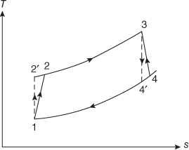
12.7.1 Reheating
Plant efficiency can be improved by reheating of the gas after it expands in the high-pressure turbine as shown in Figure 12.20.

Fig. 12.20 (a) Gas Turbine Plant with Reheater (b) T-s Diagram with Reheater
For the same expansion ratio with reheating in two stages as compared to single-stage expansion, the work output will be increased as seen on the T-s diagram. Usually, the upper limit for reheating is T3 = T5.
Now, turbine work output from LP and HP turbines is
WT = Cpg (T3 − T4) + Cpg (T5 − T6)
= Cpg ηt1 (T3 − T4′) + Cpg ηt2 (T5 − T6′)
WT =  (1)
(1)
where ηt1, ηt2 = HP and LP turbine efficiencies
Cpg = specific heat of the gas
For the isentropic processes 3–4′ and 5–6′,
![]() =
=  and
and ![]() =
= 
Substituting in Equation (1) above with ![]() = x
= x
WT =  (2)
(2)
In the above equation with T3, p1 and p2 fixed, only variable is pi. Hence for maximum work output,
![]() = 0
= 0
i. e., 
![]()
![]()
![]() =
= ![]()
Hence, ![]() =
= ![]()
∴pi = 
i. e., pi = 
Hence intermediate pressure
pi =  (3)
(3)
When, T5 = T3, TR = 1 and if ηt2 = ηt1,
pi = ![]() (4)
(4)
Thermal efficiency of the cycle is given by the following equation:
η = ![]()
=  (5)
(5)
12.7.2 Regeneration
The thermal efficiency and specific output of the gas turbine cycle can be increased by using regeneration method. In this method, the heat in the exhaust gases is used to increase the temperature of air that comes out of the compressor. This increases the temperature of air and reduces the fuel consumption in the combustion chamber. A gas turbine plant fitted with a regenerator or heat exchanger is shown in Figure 12.21.
In perfect regeneration, under ideal conditions, temperature of compressed air that comes out of the compressor at temperature T2 is increased to T5 and temperature of air after expansion in the turbine is reduced from T4 to T6 as shown on the T-s diagram in Figure 12.22.
Thus, T5 = T4 and T6 = T2, and it can be noticed that the turbine and compressor work are unchanged.
Hence, the thermal efficiency of the cycle is modified as follows:
η =  (1)
(1)
η =  as T4 = T5
=  (2)
(2)
= 

Fig. 12.21 (a) Gas Turbine with Regenerator (b) T-s Diagram

Fig. 12.22 T-s Diagram with Regenerator
= 
=  ; as
; as ![]() = TR
= TR
= 
η = ![]() ; as R =
; as R = ![]() (3)
(3)
From Equation (3), it is evident that as temperature ratio increases (TR), thermal efficiency of the cycle increases. Again, decreasing the pressure ratio term (R), thermal efficiency increases.
In an actual cycle, it is not possible to attain the condition T5 = T4. The actual temperature of air that comes out of the regenerator is lesser than T5 and is equal to T5′ as shown on the T-s diagram in Figure 12.22.
Hence, cycle efficiency
η =  (4)
(4)
Heat exchanger efficiency or effectiveness,
η = ![]()
η =  =
=  (5)
(5)
where ma, mg = mass flow rate of air and gas, respectively, with corresponding specific heats Cpa and Cpg.
In case, ma = mg and Cpa = Cpg, then the above equation reduces to
η =  (6)
(6)
Even though regenerator efficiency increases with increased heat-transfer surface area, the space and pressure loss consideration limits its use.
12.7.3 Intercooling
Another method of improving the plant efficiency is to reduce the work absorbed by the compressor stages, by adopting an intercooler in between the stages. Such an arrangement is shown in Figure 12.23.

Fig. 12.23 (a) Gas Turbine with Intercooler and (b) T-s Diagram for Perfect Intercooling
For single-stage compression, compressor work input is given by the following equation:
WC = Cp (T2′ − T1) = Cp [(T2 − T1) + (T2′ − T2)](1)
For two-stage compression, compressor work input is given by the following equation:
WC = Cp [(T2 − T1) + (T4 − T3)](2)
Comparing the above two equations, it can be noted that in the T-s diagram that
(T2′ − T2) > (T4 − T3)
Hence, work input is reduced in two-stage compression. For perfect intercooling, T3 = T1.
But in actual practice, intercooling is not perfect, and hence T3 > T1 as shown in the T-s diagram in Figure 12.24.

Fig. 12.24 Gas Turbine with Imperfect Intercooling
Considering a two stage compression, compressor work is given by
WC = Cp (T2 − T1) + Cp (T4 − T3)
= ![]()
= 
WC =  (3)
(3)
where ηC1, ηC2 = isentropic efficiency of first and second compressors, respectively,
pi = intermediate pressure between two stages,
Substituting ![]() = x and
= x and ![]() = TR, we get
= TR, we get
WC =  (4)
(4)
For minimum compressor work, with pressures p1 and p2 and temperatures T1 and T3 fixed, we have,
![]() = 0
= 0
 = 0
= 0
i.e.,  = 0
= 0
i.e.,  = 0
= 0
 =
= 
i.e., ![]() =
= 
Hence, ![]() =
= ![]()
∴pi = 
i. e., pi = 
In other words, for imperfect intercooling,
pi =  (5)
(5)
For perfect intercooling, TR = 1 and if ηC1 = ηC2, then
pi = ![]() (6)
(6)
Substituting this value in Equation (4) above,
For perfect intercooling,
WC =  =
= 
WC = 
Thermal efficiency of the turbine is given by the following equation:
ηth = 
In the above equation as WC = (T2 − T1) + (T4 − T3) reduces and turbine work WT = (T5 − T6) remains same, thermal efficiency of the cycle decreases as (T5 − T4) = heat addition increases in case of imperfect intercooling, as compared to perfect intercooling.
Example 12.1
Air is drawn in a gas turbine at 18°C and 1 Bar and leaves the compressor at 5 Bar. Data observed are the following:
Temperature of gases entering the turbine = 678°C.
Pressure loss in combustion chamber = 0.1 Bar.
ηcompressor = 85% γ = 1.4 for air
ηcombustion = 85% Cp = 1.024 kJ/kg K for gas
ηturbine = 80%
Find the (i) quantity of air, if plant develops 1065 kW; (ii) heat supplied per kg of air circulated and (iii) thermal efficiency of cycle.
Solution: The cycle is shown on the T-s diagram below.
Consider processes 1 and 2, ![]() =
= ![]() =
=  = 1.584
T2 = T1 × 1.584 = 300 × 1.584 = 475.2 K.
![]() =
= ![]()
T4 = ![]()
= ![]()
![]() = 519.57 K
= 519.57 K

- Efficiency of the turbine without regenerator,
η =

For unit mass of air,
=

=

= 36.87%
- Efficiency of the turbine with regenerator,
Regenerator efficiency
 =
= 
T5′ =
 (T5 − T2) + T2
= 0.60 (519.57 − 475.2) + 475.2
= 26.62 + 475.2
= 501.822 K
η =

=

= 39.93%
Example 12.2
In an open-cycle constant pressure gas turbine unit air enters compressor at 1 bar and 300 K. The pressure of air after compression is 4 bar, the isentropic efficiencies of compressor and turbine are 80 per cent and 85 per cent, respectively. The air fuel ratio is 90:1. Calculate the power developed and thermal efficiency of the cycle if the flow rate of air is 3 kg/s. Take Cp = 1.005 kJ/kgK and γ = 1.4 for air and gases CV = 42,000 kJ/kg
Solution:
- Power developed:
Temperature at the end of isentropic compression is given by
 =
= 
T2′ = (300)

T2′ = 445.8 K

Actual temperature rise during compression is
T2 − T1 =
 =
= 
= 191
T2 = T1 + 178 = 300 + 191
T2 = 491 K
Heat supplied by the fuel = heat taken by the gases:
mf CV = (ma + mf) Cp (T3 − T2)
CV =

42,000 = (90 + 1) × 1(T3 − 491)
T3 =

T3 = 952.54 K
The work required to drive the compressor is
WC = CP (T2 − T1)
WC = 1.005 (491 − 300)
WC = 191.96 kJ/kg of air per sec.
Temperature at the end of isentropic expansion is
T4′ =
 =
=  = 641.01 K
∴ Actual temperature drop = T3 − T4 = ηt (T3 − T4′)
= 0.85 (952.54 − 641.01) = 264.8°C
T4 = T3 − 264.8 = 952.54 − 264.8
T4 = 687.74 K
Total turbine work is
Wt = m Cp (T3 − T4)
=

Wt = 267.74 kJ/kg of air per sec
∴Net work output = WT − WC = 267.74 − 191.96
= 75.78 kW/kg of air
Net power developed by the turbine = 75.78 × 3 = 227.34 kW
- Thermal efficiency
Heat supplied per kilogram of air =
 = 466.67 kJ/kg of air
Thermal efficiency, ηt =
 = 16.24%
Example 12.3
In a regenerative gas turbine cycle, air enters the compressor at 1 bar 15°C. Pressure ratio = 6. The isentropic efficiencies of compressor and turbine are 0.8 and 0.85, respectively. The maximum temperature in the cycle is 800°C. The regenerator efficiency = 0.78, Assume Cp = 1.1 kJ/kgK and γ = 1.32 for the combustion products and find the cycle efficiency.
Solution: The gas turbine cycle is shown as the T-s diagram.
Pressure ratio β = ![]() = 6
= 6
p2 = 6 bar
For the actual cycle, temperature of air at the compressor exit is given by
T2 = 
= 
= 528.66 K

Compressor work is given by
WC = CP (T2 − T1) = 1.005 (528.66 − 288)
= 241.86 kJ/kg
Considering processes 3 and 4, the actual temperature of gases at turbine exit is given by
T4 =  =
= 
= 751.66 K
Turbine work is given by
WT = mgCpg (T3 − T4); (ignoring fuel mass, ma = mg)
= 1 × 1.1 (1073 − 751.66)
= 353.47 kJ/kg
Net work output
= WT − WC = 353.47 − 241.86
= 111.6 kJ/kg
Now, efficiency of the regenerator is given by
ϵ = ![]() ; T5 = T4 for ideal conditions
; T5 = T4 for ideal conditions
0.78 = ![]()
T5′ = 528.66 + 0.78 (751.66 − 528.66)
= 702.8 K
Thermal efficiency of the cycle, assuming ma = mg and Cpa = Cpg,
η = 
= 
= ![]()
= 24.49%
Considering Cpg and Cpa
η = 
= 27.4%
Example 12.4
In an open-cycle gas turbine plant, air enters the compressor at 1 bar and 27°C. The pressure after compression is 4 bar. The isentropic efficiencies of the turbine and the compressor are 85 per cent and 80 per cent, respectively. Air fuel ratio is 80:1. The calorific value of the fuel used is 42,000 kJ/kg and mass flow rate of air is 2.5 kg/s. Determine the power output from the plant and the cycle efficiency. Assume that Cp and γ to are same for both air and products of combustion.
Solution:
Given data: p1 = 1 bar, T1 = 300 K
p2 = p3 = 4 bar, ηT = 0.85, ηc = 0.80
ma = 2.5 kg/s; ma/mf = 80
CV = 42,000 kJ/kg
Cp = 1.005 kJ/kgK (assumed)
γ = 1.4 (assumed)

For processes 1 and 2′,
![]() =
= 
T2′ = T1
= 300
T2′ = 446 K
Compressor efficiency ηc = ![]()
T2 = T1 + 
∴ T2 = 300 + ![]()
T2 = 482.5 K
For processes 3 and 4′,
![]() =
= 

![]() = T3
= T3 (1)
(1)
Heat supplied per unit time:
Q2 − 3 = mf CV
= ![]()
= 1312.5 kJ/s
But Q2 − 3 = (ma + mf)h3 − mah2
h3 = ![]()
T3 = 
= 
T3 = 992.3 K
From Equation (1),
![]() = T3
= T3 = 992.3
= 667.5 K
Turbine efficiency is given by
ηT = ![]()
∴T4 = T3 − ηT(T3 − T4′)
T4 = 992.3 − 0.85 (992.3 − 667.5)
T4 = 716.22 K
Compressor work per unit time = WC = maCp (T2 − T1)
= 2.5 × 1.005 (482.5 − 300) = 458.53 kJ/s
= 458.53 kW
Turbine work per unit time = WT = (ma + mf) Cp (T3 − T4)
WT = (2.5 + 2.5/80) × 1.005 × (992.3 − 716.22)
= 702.32 kW
Net work output ![]() = 702.32 − 458.53
= 702.32 − 458.53
= 243.79 kW
Cycle efficiency ηcycle =  =
= ![]()
= 18.58%
Example 12.5
A gas turbine power plant operates on ideal Brayton cycle. The minimum and maximum cycle temperature are T1 = 300 K and T3 = 800 K, respectively. Find the value of the optimum pressure ratio for maximum specific work output and the cycle efficiency for this condition. Is it possible to improve this cycle efficiency by including regenerator? Substantiate.
Solution: Given data
Tmin = T1 = 300 K
Tmax = T3 = 800 K

Optimum pressure ratio for maximum output is given by
βopt = ![]() =
= 
=  = 5.565
Cycle efficiency, η = 1 −  = 1 −
= 1 − ![]()
η = 1 − ![]() = 38.76%
= 38.76%
Condition for maximum work output is satisfied for
![]() =
= 
But ![]() =
= 
![]() =
= 
T2 = T4 = ![]()
As T2 = T4, regenerator is not required.
Example 12.6
A simple gas turbine plant operating on the Brayton cycle has air entering the compressor at 10 kPa and 27°C. The pressure ratio = 9 and maximum cycle temperature = 727°C. What will be the percentage change in cycle efficiency and net work output if the expansion in the turbine is divided into two stages each of pressure ratio 3, with intermediate reheating to 727°C? Assume compression and expansion are ideal isentropic.
Solution:
- Single-stage expansion
Given that
p2 = 1 bar
T1 = 300 K
= 9
T3 = T5 = 1000 K
For the processes 1 and 2,
=
 =
=  = 1.875
∴ T2 = T1 × 1.875 = 300 × 1.875 = 562.5 K
For the processes 3 and 4,

T4 =
 =
= = 533.3 K
Compression work, WC = CP(T2 − T1)
= 1.005 (562.5 − 300)
WC = 263.8 kJ/kg
Expansion work, WT = CP(T3 − T4)
= 1.005 (1000 − 533.3)
WT = 469.03 kJ/kg
Net work output
 = WT − WC
= 469.03 − 263.81 = 205.22 kJ/kg
Heat supplied QS = CP(T3 − T2)
= 1.005 (1000 − 562.5)
= 439.68 kJ/kg
Cycle efficiency (η)1 =

=
 = 0.4667 = 46.67%
 - Expansion in two stages with pressure ratio in each stage = 3
= (3)0.286 = 1.369
T4a =
 = 730.4 K
As the pressure ratio in the second stage is the same and air is reheated to 1000 K,
T6 = T4a = 730.4 K
Work of expansion in each stage will be the same.
∴ Total work of expansion
WT = 2CP (T3 − T4a)
= 2 × 1.005 (1000 − 730.4)
= 541.89 kJ/kg
Work of compression will remain the same, that is, 263.81 kJ/kg.
Net work output
 = WT − WC
= 541.89 − 263.81
= 278.08 kJ/kg
Heat supplied QS2 = heat supplied in combustion chamber + heat supplied in the reheater
= CP(T3 − T2) + CP(T5 − T4a)
= 1.005 (1000 − 562.5) + 1.005 (1000 − 730.4)
= 439.68 + 270.94
= 710.62 kJ/kg
Cycle efficiency
η2 =
 =
=  = 0.3913 = 39.13%
Percentage change in efficiency
η =
 =
= 
= −16.15%
Percentage change in work output
=

=
 = 0.355 = 35.5%
Example 12.7
A gas turbine power plant operates on the simple Brayton cycle with air as the working fluid and delivers 32 MW of power. The minimum and maximum temperatures in the cycle are 310 K and 900 K, respectively, and the pressure of air at the compressor exit is eight times the value at the compressor inlet. Assuming an isentropic efficiency of 80 per cent for the compressor and 86 per cent for the turbine, determine the mass flow rate of air through the cycle.

Solution: Given data
![]() = T3 = 900 K
= T3 = 900 K
![]() = T1 = 310 K
= T1 = 310 K
rP = 8, = 0.8, = 0.86
For processes 1 and 2, T2′ = T1 ![]()
T2′ = ![]() = 561.55 K
= 561.55 K
Considering compressor efficiency,
= ![]()
∴ = T1 + ![]()
= 561.55 + ![]()
= 624.44 K
For process 3 and 4,
T4′ = ![]()
= ![]()
= 496.84 K
Considering turbine efficiency,
ηT = ![]()
∴ T4 = T3 − ![]()
= 900 − 0.86 (900 − 496.84)
= 553.3 K
Compressor work is given by
WC = CP(T2 − T1) = 1.005 (624.44 − 310)
= 316.01 kJ/kg
Turbine work is given by
WT = CP(T3 − T4)
= 1.005 (900 − 553.3)
= 348.43 kJ/kg
Net work,
![]() = WT − WC = 32.42 kJ/kg
= WT − WC = 32.42 kJ/kg
Power P = ![]()
∴ m = 
m = ![]() = 987.05 kg/s
= 987.05 kg/s
Example 12.8
A gas turbine plant draws in air at 1.013 bar, 10°C and has a pressure ratio of 5.5. The maximum temperature in the cycle is limited to 750°C. Compression is conducted in an uncooled rotary compressor having an isentropic efficiency of 82 per cent and expansion takes place in a turbine with an isentropic efficiency of 85 per cent. A heat exchanger with an efficiency of 70 per cent is fitted between the compressor outlet and combustion chamber. For an air flow of 40 kg/s, find the (i) overall efficiency of cycle, (ii) turbine output, (iii) air–fuel ratio if the calorific value of fuel used is 45.22 MJ/kg.
Solution: All the processes are shown on the T-s diagram below.
Considering processes 1 and 2,
T2′ = T1 ![]()
ηc = ![]()
0.82 = ![]()
= 498.85 K
Considering expansion in turbine,
T4 = 
Considering turbine efficiency,
ηt = ![]()
0.85 = ![]()
T4 = 688.36 K
Considering heat exchanger efficiency,
ηHE = ![]()
0.70 = ![]()
∴ T5 = 640.98 K
- Overall efficiency of cycle
Cycle efficiency is given by
η =

=

= 31%
- Turbine output
Net work done,
 = WT − WC = 4751.6 kJ/kg
Output power = 1 × 4751.6
= 4751.6 kW
- Air–fuel ratio
Making heat balance in the combustion chamber,
mf × CV = (ma + mf) Cpa
mf × 45.22 × 103 = (40 + mf) × 1.005 × (1023 − 640.98)
mf × 117.78 = 40 + mf
mf =

∴
 = 116.78
12.8 FREE-PISTON ENGINE PLANT – LIMITATION, APPLICATION AND ADVANTAGES
Free-piston engines are typically diesel powered, opposed piston engines with mechanical synchronization of the two pistons. The synchronization mechanism did, in addition to evening out possible force differences, also drive the accessories such as fuel injection pump, oil pump and water pump. Free-piston gas generators were considered for use in large-scale power plants, and at a later stage for vehicle propulsion in the late 1940s. General Motors and Ford Motor Company had working prototypes of these engines aimed for vehicle propulsion. Larger free-piston gas generators were installed in a number of stationary power plants and in some marine installations.
In a free-piston engine, the piston is ‘free’ and its motion is not restricted by the position of a rotating crankshaft, unlike in a conventional engine. The motion is determined by the interaction between the gas and load forces acting upon it. Because of this, a free-piston engine offers (i) variable stroke length, (ii) the need for active control of piston motion, (iii) potential reductions in frictional losses and (iv) possibilities to optimize engine operation by varying compression ratio.
R. P. Pescara [2] was the first to invent a free-piston engine with his patent dating from 1928. Free-piston engines may be classified as single, dual, opposed piston and gas generators. A brief account of these engines is discussed further.
1. Single piston
A single piston free-piston engine is shown in Figure 12.25. This engine essentially consists of three parts, namely a combustion cylinder, a load devic, and a rebound device to store the energy required to compress the next cylinder charge. The hydraulic cylinder serves the purpose of both load and rebound device. The rebound device is used to accurately control the amount of energy put into the compression process, and hence to regulate the compression ratio and stroke length. The system is simple in design but offers high controllability compared to the other free-piston engine configurations.

Fig. 12.25 Single-Piston Hydraulic Free-Piston Engine [3]
2. Dual piston
Figure 12.26 shows a hydraulic dual piston free-piston engine [4]. The dual piston engine configuration eliminates the need for a rebound device, as the (at any time) working piston provides the work to drive the compression process in the other cylinder. This allows a simple and more compact device with higher power to weight ratio.
The major drawback of this engine is that it is difficult to control of piston motion, in particular stroke length and compression ratio. This is because the combustion process in one cylinder drives the compression in the other, and small variations in the combustion will have high influence on the next compression. Experimental work with dual piston engines has reported high sensitivity to load nuances and high cycle-to-cycle variations [5, 6].

Fig. 12.26 A Hydraulic Dual Piston Free-Piston Engine [4]
3. Opposed piston
Figure 12.27 shows an opposed piston free-piston engine, with a mechanical piston synchronization mechanism. An opposed piston free-piston engine consists of two single piston units connected with a common combustion chamber. Each piston requires a rebound device, and a load device may be coupled to one or both of the pistons.

Fig. 12.27 A Hydraulic Dual Piston Free-Piston Engine
In the earlier days, these engines were used as air compressors and later as gas generators in large-scale plants, using a number of units feeding a single-power turbine.
The advantages of the opposed piston are the following:
- Perfectly balanced and vibration-free design.
- Reduced heat transfer losses due to the opposed piston cylinder as cylinder head is eliminated
- Allows uniflow scavenging resulting in high scavenging efficiency.
The disadvantages of the opposed piston are the following:
- Piston synchronization mechanism is a must.
- Usage of dual set of the main components makes the engine complicated and bulky.

Fig. 12.28 An Opposed Piston Free-Piston Gas Generator Plant
4. Gas generators
Figure 12.28 illustrates an opposed piston free-piston gas generator plant. Free-piston gas generators use free-piston engines that feed hot gases to a power turbine. The engine is used to supercharge the intake air, and the entire output work is utilized by the power turbine. In the mid-twentieth century, free-piston gas generators were used in some large-scale marine and stationary power plants. Free piston engines are started by rapidly introducing compressed air into the bounce chambers as shown in Figure 12.28. These engines were highly supercharged and operated on higher mean effective pressures than conventional diesel engines [3].
The most important advantages of free-piston gas generators are the following:
- Compared to a conventional gas turbine, the free-piston gas generator offers high compression and pressure ratios.
- As the work needed to compress the intake air is already extracted from the gas when supplied to the power turbine, the gas fed to the turbine is at a lower temperature, which reduces the materials requirements and allows the turbine to be placed further away from the combustor without extensive heat transfer losses.
- Low fuel quality requirements,
- Vibration-free design,
- Good dynamic response and low turbine material requirements due to lower inlet temperatures.
- The fuel economy of the free-piston gas generator power plant was competitive with conventional diesel engines and 80–100 per cent better than conventional gas turbine plants [3]. The specific weight was somewhere between the low specific weight of the gas turbine and the high specific weight of the conventional diesel engine.
- Free-piston gas generator efficiency is higher compared to the conventional gas turbine due to the higher compression pressures. Free-piston engines could achieve an end-of-compression pressure of 100 times the atmospheric pressure as against six in the simple-type gas turbine [7].
Some of the limitations of these engines are the following:
- High development efforts were put into both conventional diesel engines and gas turbine technology, giving rapid performance increases.
- Due to the difficulty in matching of a pulsating-flow compressor with a continuous-flow turbine, part-load efficiency is lower. Due to this, the gas generator is limited to constant power applications [8, 9].
- High failure rates and low lifetime and availability were reported, related to high pressure and temperature operation [9].
- The engines did not provide large advantages in weight or fuel economy compared to conventional engines and could not compete with the power to weight ratio of the gas turbine.
With the maturing of conventional gas turbine technology, development of the free-piston gas generator was largely abandoned in the early 1960s. [8, 9, 10]
12.9 COMBINED CYCLE POWER PLANTS AND COMPARISON
Simple cycle gas turbine (GTs) plants using natural gas and fuel oil operate at around 33 percent and 25 per cent efficiency, respectively, major part of the heat being wasted as thermal energy in the hot exhaust gases.
Combining of multiple thermodynamic cycles to generate power, overall plant efficiency can be increased up to 60 per cent by using a heat recovery steam generator (HRSG). The HSRG captures heat from high-temperature exhaust gases to generate steam, which is then supplied to a steam turbine to generate additional electric power. The cycle working under this principle is known as combined cycle. In most of the instance a combined cycle power plant utilizes gas turbines in conjunction with a steam turbine and is called a combined cycle gas turbine (CCGT) plant. Different configurations of CCGT power plants are in use where each GT has its own associated HRSG, and multiple HRSGs supplying steam to one or more steam turbines. For example, in a plant with a 3 × 1 configuration, three GT/HRSG trains supply to one steam turbine. Similarly, there can be 1 × 1, 2 × 1 or 4 × 1 arrangements also. The steam turbine capacity is decided to match the number and capacity of supplying GTs/HRSGs. These types of power plants are being installed in increasing numbers round the world where there is access to substantial quantities of natural gas.
12.9.1 Combined Cycle Principles of Operation
The HRSG is basically a heat exchanger popularly known as a boiler, or comprises a series of heat exchangers. It generates steam for the steam turbine exchanging heat from the hot exhaust gas flow from a gas turbine through heat exchanger tube banks. The tubes are arranged in sections, or modules also known as economizers, evaporators, superheater/reheater and preheaters. The fluid circulation in HRSG could be either natural or forced circulation using pumps. Saturated steam from the steam drums or once-through system is passed through superheater or reheater tubes to superheat the steam. The superheated steam produced by the HRSG is supplied to the steam turbine where it expands through the turbine blades, imparting rotation to the turbine shaft. The energy delivered to the generator coupled to the drive shaft is converted into electricity. After exiting the steam turbine, the steam condenses in a condenser and fed back to the HRSG. Figure 12.29 shows a schematic diagram of a combined cycle gas turbine plant.
12.9.1.1 CCGT Design Considerations
Depending on the exhaust gas characteristics HSRGs are designed and configurations, steam requirements, etc., are decided later. Due to the high temperature of exhaust gases available at the gas turbine exit (600°C), GTs are designed to produce steam at multiple pressure levels (high-pressure steam in a large CCGT plant can reach up to 110 bar) to optimize energy recovery. Generally, three sets of heat exchanger modules – one each for high pressure (HP) steam, intermediate pressure (IP) steam, and low pressure (LP) steam – are used for this purpose.
The HRSGs present operational constraints on the CCGT power plant owing to their location, directly downstream of the gas turbines. Due to the changes in temperature and pressure of the exhaust gases thermal and mechanical stresses are set up.

Fig. 12.29 Combined Cycle Power Plant
When CCGT power plants are operated under fluctuating load conditions, characterized by frequent starts up and shut downs or when operating under part-load conditions, thermal stresses developed could cause damage to some components of the HRSG. The HP steam drum and superheater headers are subjected to the highest exhaust gas temperatures, and hence are more prone to reduced mechanical life. Some important design and operating considerations are the following:
- Temperatures of the gas and steam that the module materials can withstand
- Mechanical stability for turbulent exhaust flow
- Corrosion of HRSG tubes
- Steam pressures to decide drum thickness
12.9.2 Coupled Cycle – GT–ST Plant Operation
In this system, an open-circuit gas turbine has a compressor, a combustor and a turbine. For this type of cycle, the input temperature to turbine and the output temperature of flue gases are very high. This high-temperature flue gases have heat energy high enough to provide heat for a second cycle that uses steam as the working medium, that is, thermal power plant. Figure 12.30 shows the working principle of combined cycle gas turbine (CCGT) plant. Different components of the plant are discussed further in detail.
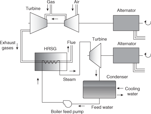
Fig. 12.30 Working Principle of Combined Cycle Gas Turbine Plant
1. Air Inlet system
Air is drawn though the large air inlet section where it is cleaned, cooled and controlled. Majority of all heavy-duty gas turbines are designed to operate under a wide variety of climatic and environmental conditions due to inlet air filtration systems. These filtration systems are specifically designed to suit the plant location. Under normal operating conditions, the inlet system has the capability to process the air by removing contaminants to levels below those that are harmful to the compressor and turbine. In general, the incoming air may have contaminants in solid, liquid and gaseous states in addition to corrosive components. Gaseous contaminants include ammonia, chlorine, hydrocarbon gases, sulfur in the form of H2S, SO2, discharge from oil cooler vents, etc. Some of the liquid contaminants include chloride salts dissolved in water (sodium, potassium), nitrates, sulfates and hydrocarbons, etc. Solid contaminants may include sand, alumina and silica, rust, dust particles, alumina and silica, calcium sulfate, ammonia compounds from fertilizer and animal feed operations, airborne seeds, etc. In addition to these, some corrosive agents such as chlorides, nitrates and sulfates may also deposit on compressor blades inducing stress corrosion attack and/or cause corrosion pitting. Alkali metals such as sodium and potassium may also combine with sulfur to form a highly corrosive agent that may attack portions of the hot gas path. These contaminants are removed by passing through various types of filters. Gas phase contaminants such as ammonia or sulfur that cannot be removed by filtration are removed based on special methods.
2. Turbine system
The purified air is then compressed and mixed with natural gas and ignited in the combustion chamber after injecting the fuel. The high-pressure gas stream generated in the combustion chamber expands in the turbine and spins the turbine rotor and a generator, producing electricity. Heat of the gas turbine's exhaust is further passed through the heat recovery steam generator (HRSG), where live steam at temperature between 420°C and 580°C is generated, which is used as a working fluid in the secondary circuit.
3. Heat recovery steam generator
In heat recovery steam generator (HRSG), heat exchange takes place between the highly purified water flowing in tubes and the hot flue gases surrounding them, generating steam. As explained earlier, steam expands in the turbine to run the turbine rotor and hence a coupled generator, to produce electricity. The hot gases leave the HRSG at around 140°C before being discharged into the atmosphere. The steam condensing and water system in this circuit are similar to that in a typical thermal power plant. The HRSG takes more time to warm up from cold conditions compared to hot conditions.
12.9.2.1 Configuration of CCGT Plants
The combined cycle system may have single-shaft and multi-shaft configurations. A single-shaft system consists of a gas turbine, a steam turbine, a generator and a heat recovery steam generator (HRSG). The gas turbine and steam turbine are coupled to the single generator on a single shaft. In a multi-shaft system, one or more gas turbine-generators and HRSGs are used to supply steam through a common header to a separate single-steam turbine generator. Overall investment on a multi-shaft system is about 5 per cent higher compared to a single-shaft system. The major disadvantage of multi-shaft system is that the number of steam turbines, condensers and condensate systems, cooling towers and circulating water systems also proportionately increases to match the number of gas turbines.
12.9.2.2 Efficiency of CCGT Plant
Roughly, the steam turbine cycle produces one-third of the power and gas turbine cycle produces two-thirds of the power output of the CCGT. By combining both gas and steam cycles, high input temperatures and low output temperatures can be achieved. The efficiency of the cycles adds because they are powered by the same fuel source. To increase the power system efficiency, it is necessary that the HRSG be optimized, which serves as the critical link between the gas turbine cycle and the steam turbine cycle with the objective of increasing the steam turbine output.
Overall efficiency of the combined cycle power plant depends on the performance of HRSG. There are instances of electric efficiency of a new combined cycle power station reaching 58 percent at continuous output. In addition, combined cycle units may be utilized to deliver low temperature heat energy for industrial processes, district heating and other uses. This is called cogeneration, and such power plants are of then referred to as a combined heat and power (CHP) plant.
The efficiency of CCGT is increased by supplementary firing and blade cooling. A gas turbine cooling air (TCA) cooler, with a heat exchanger using feed water, and a fuel gas heater (FGH) were also used to further enhance the efficiency of the plant in Kawasaki Thermal Power Station. This minimized the loss of heat energy allowing the plant to achieve higher thermal efficiency, outperforming conventional combined cycle plants. In this plant, supplementary firing was arranged at HRSG and in gas turbine a part of the compressed air flow bypasses to cool the turbine blades.
12.9.2.3 Fuels
The turbines used in combined cycle plants are commonly fuelled with natural gas, and it is more versatile than coal or oil and can be used in 90 per cent of energy applications. Combined cycle plants are usually powered by natural gas, although fuel oil, synthesis gas or other fuels can be used.
12.9.2.4 Emissions Control
In order to control the emission, different tools and techniques are used, namely, a selective catalytic reduction (SCR) system, aqueous ammonia solution, a low NOx combustor and a dry NOx removal apparatus, as discussed below:
1. Selective catalytic reduction
To control the emissions in the exhaust gas so that it remains within permitted levels as it enters the atmosphere, the exhaust gas passes though two catalysts located in the HRSG. One catalyst controls carbon monoxide (CO) emissions, whereas the other catalyst controls oxides of nitrogen, (NOx) emissions.
- Aqueous ammonia: Apart from the SCR, a mixture of 22 per cent ammonia and 78 per cent water, known as aqueous ammonia is also injected into system to further reduce NOx levels.
- To reduce NOx emissions that increase with the combustor exit gas temperature (1500°C), a low NOx combustor can also be used.
- A dry NOx removal apparatus can be built in the heat recovery steam generator to operate the plant confirming environmental regulation limits.
12.9.2.5 Advantages and Disadvantages of CCGT Plants
Advantages
- Fuel efficiency: As against the conventional power plants turbines fuel-conversion efficiency of 33 per cent, turbines in combined cycle power plant have a fuel-conversion efficiency of 50 per cent or more. This means the CCGT plant use only 50 per cent of fuel compared to a conventional plant to generate same amount of electricity.
- Low capital costs: The capital cost for building a combined cycle unit is two-thirds the capital cost of a comparable coal-based power plant.
- Ability to handle variety of fuel sources: The turbines used in combined cycle plants are fuelled with natural gas, which is more versatile than a conventional coal or oil. To meet the energy demand, the plant can also be designed to run on alternative fuels such as agriculture-based bio gas.
- Lower emission and fuel consumption: The specific fuel consumption of combined cycle plants is less (fuel per kilowatt hour) and produces fewer emissions than conventional thermal power plants. This reduces the environmental damage caused by electricity production. The fuel used in CCPT is much cleaner when compared to coal-fired power plant.
- 5. Commercial availability: Combined cycle units are commercially available from all parts of the world. They can be easily manufactured, shipped, transported and commissioned.
Disadvantages
- The gas turbine can only use natural gas or high-grade oils such as diesel fuel.
- 2. Its operation is location specific because the combined cycle can be operated only in locations where these fuels are available and cost effective.
12.9.3 Thermodynamic Analysis of a Simple Combined Cycle GT–ST Plant
Consider a simple combined cycle plant, the gas turbine drives one electric generator and the steam turbine runs another, as illustrated in Figure 12.31. For the analysis purpose, let us ignore the losses in the heat exchanger.

Fig. 12.31 Thermodynamic Analysis of a Simple Combined Cycle Plant
Let ![]() efficiency of the gas turbine cycle (topping cycle)
efficiency of the gas turbine cycle (topping cycle)
![]() inlet temperature of gas in gas turbine cycle (topping cycle)
inlet temperature of gas in gas turbine cycle (topping cycle)
![]() heat rejected in gas turbine cycle (topping cycle)
heat rejected in gas turbine cycle (topping cycle)
![]() efficiency of the steam turbine cycle (bottoming cycle)
efficiency of the steam turbine cycle (bottoming cycle)
![]() inlet temperature of steam in the steam turbine cycle (bottoming cycle)
inlet temperature of steam in the steam turbine cycle (bottoming cycle)
![]() heat rejected in the steam turbine cycle (bottoming cycle)
heat rejected in the steam turbine cycle (bottoming cycle)
Efficiency of the topping plant is given by
![]()
![]()
![]()
![]()
Efficiency of the topping plant is given by
![]()
![]()
![]()
![]()
Combined cycle efficiency is given by
![]()
 =
= 
![]()
![]()
![]()
![]()
![]()
If there are n number of cycles in series, then combined cycle efficiency is given by
![]()
![]()
![]()
Or ![]()
![]()
Considering the gas turbine cycle (topping cycle)
Work or power delivered by the steam turbine plant is given by
![]()
Considering the exhaust of the turbine, we have
![]()
Work or power delivered by the steam turbine plant is given by
![]()
Total power delivered by the steam and gas turbine is given by
![]()
![]()
Figure 12.32 shows the plot of ![]() v/s
v/s ![]() for various values of combined cycle efficiency,
for various values of combined cycle efficiency, ![]() The shaded rectangle in this graph illustrates that overall efficiencies above 0.50 are possible with
The shaded rectangle in this graph illustrates that overall efficiencies above 0.50 are possible with ![]() as low as 0.20 if the corresponding
as low as 0.20 if the corresponding ![]() is at least 0.38. With a steam turbine efficiency of 0.32 and a gas turbine efficiency of 0.42, the combined cycle efficiency is
is at least 0.38. With a steam turbine efficiency of 0.32 and a gas turbine efficiency of 0.42, the combined cycle efficiency is ![]() = 0.60. If the steam turbine efficiency is 0.40, then
= 0.60. If the steam turbine efficiency is 0.40, then ![]() = 0.64.
= 0.64.

Fig. 12.32 Plot of ![]() v/s
v/s ![]() for Various Values of Combined Cycle Efficiency [11]
for Various Values of Combined Cycle Efficiency [11]
Figure 12.33 shows the variation of efficiency of gas turbine, steam turbine and combined cycle plant with gas turbine exhaust temperature, T2. It is evident from the plot that combined cycle offers best and highest efficiency compared to GT and ST plants as turbine exhaust temperature also increases.

Fig. 12.33 Variation of Efficiency of Various Cycles with Gas Turbine Exhaust Temperature, T2 Source: Kehlhofer, R., R. Bachmann, H. Nielsen, and J. Warner, 1999, Combined Cycle Gas and Steam Turbine Power Plants, 2nd edition. Tulsa, OK: PennWell.
12.10 LAYOUT OF GAS TURBINE PLANT
Figure 12.34 shows typical layout of a gas turbine plant. The air filler is used to clean the air. The air leaving the air filler flows to the LP compressor. The compressed air then flows through the intercooler and then it enters the high-pressure compressor. The air leaving the air compressor flows through the heat exchanger and the hot air flows to the combustion chamber. Products of combustion then enter in to low-pressure turbine, where it expands doing useful work.

Fig. 12.34 Layout of Gas Turbine Plant
12.11 QUESTIONS
12.11.1 Objective Questions
- In a simple Brayton cycle, the pressure ratio is 8 and temperatures at the entrance of compressor and turbine are 300 K and 1400 K, respectively. Both compressor and gas turbine have isentropic efficiencies equal to 0.8. For the gas, assume a constant value of p c (specific heat at constant pressure) equal to 1 kJ/kgK and ratio of specific heats as 1.4. Neglect changes in kinetic and potential energies.
- The power required by the compressor in kW/kg of gas flow rate is
- 194.7
- 243.4
- 304.3
- 378.5
- The thermal efficiency of the cycle in percentage (%) is
- 24.8
- 38.6
- 44.8
- 53.1
- The power required by the compressor in kW/kg of gas flow rate is
- An ideal Brayton cycle, operating between the pressure limits of 1 bar and 6 bar, has minimum and maximum temperatures of 300 K and 1500 K. The ratio of specific heats of the working fluid is 1:4. The approximate final temperatures in Kelvin at the end of the compression and expansion processes are, respectively,
- 500 and 900
- 900 and 500
- 500 and 500
- 900 and 900
- A gas turbine develops 120 kJ of work which the compressor absorbs 60 kJ of work and the heat supplied is 200 kJ. If a generator that would recover 40 per cent of the heat in exhaust were used, then the increase in the overall thermal efficiency would be
- 10.2%
- 8.6%
- 6.9%
- 5.7%
- In a gas turbine cycle, the turbine output is 600 kJ/kg the compressor work is 400 kJ/kg and the heat supplied is 1000 kJ/kg. The thermal efficiency of the cycle is
- 20%
- 40%
- 60%
- 80%
- In a single-stage cycle gas turbine, the mass flow through the turbine is higher than the mass flow through the compressor because
- the specific volume of air increase by use of inter cooler
- the temperature of air increases in the reheater
- the combustion of fuel takes place in the combustion chamber
- the specific heats at constant pressure for incoming air and exhaust gases are different
- Consider the following statement with reference to a gas turbine cycle:
- Regeneration increases thermal efficiency.
- Reheating decrease thermal efficiency.
- Cycle efficiency increases when maximum temperatures of in cycle is increased.
Identify the correct statements using the code given below:
- 1, 2 and 3
- 2 and 3
- 1 and 2
- 1 and 3
- The use of regenerator in a gas turbine cycle increases
- output but has no effect on efficiency
- outpoint but has no effect on efficiency
- both efficiency and out put
- efficiency but decreases output
- Consider the following statements comparing I.C. engines and gas turbines
- Gas turbines are simple, compact and light in weight
- Complete expansion of working substances is possible in gas turbine
- There is flexibility in the design of different components of gas turbines.
- Even low-grade fuels can be burnt in gas turbines.
Select the correct statements using the codes given below:
- 1, 2 and 3
- 1, 3 and 4
- 2, 3 and 4
- 1, 2 and 4
- Mechanical efficiency of a gas turbine as compared to internal combustion reciprocating engine is
- same
- lower
- higher
- none of these
- The pressure ratio for a gas turbine is about
- 15–20
- 10–15
- 5–10
- 3–5
- For a fixed turbine inlet temperature, increasing the pressure ratio thermal efficiency of the cycle
- decreases
- first increases and then decreases
- increases
- first decreases and the increases
- Reheating in a multistage gas turbine results in
- decreased work ratio
- increased work ratio
- same work ratio
- none of these
- Gas turbine used in aircraft is
- open-cycle turbine
- closed-cycle turbine
- constant volume turbine
- none of these
- In a multistage compressor, function of the intercooler is to
- increase the efficiency, work done and fuel consumption
- increase the efficiency, reduce work done, and fuel consumption
- increase work done, reduce efficiency and fuel consumption
- decrease efficiency work done and fuel consumption
Answers
- 1(i). c 1(ii). a 2. a 3. d 4. a 5. d 6. d 7. c 8. b 9. c 10. b 11. b 12. b 13. a 14. b
12.11.2 Review Questions
- Derive an expression for the work output of a gas turbine unit in terms of pressure ratio and maximum and minimum temperatures T3 and T1.
- Discuss the methods used for increasing thermal efficiency and specific output of open cycle gas turbine.
-
- Derive the relation for optimum pressure ratio for maximum work of gas turbine and show that it is a function of limiting temperatures.
- Discuss the merits of gas turbines as compared with I.C. engines and steam turbines.
- Compare open-cycle and closed-cycle gas turbines.
- Show that the net work output per kilogram of air in an ideal Brayton cycle is maximum when the pressure ratio is such that the compressor and turbine exit temperatures are same.
- Sketch the flow diagram and the corresponding temperature-entropy diagram of a gas turbine plant having two-stage compression with intercooling, a regenerator and two-state expansion with reheating in between stages. Mark the state points clearly on both the diagrams.
- Show that the efficiency at air standard Brayton cycle is a function of isentropic pressure ratio.
- Explain briefly the effects of (i) regeneration, (ii) intercooling and (iii) reheating on Brayton cycle efficiency with a T-s diagram.
-
- Derive the expression of optimum pressure ratio for maximum net work output in an ideal Brayton cycle. What is the corresponding cycle efficiency?
- List down the methods of improving the efficiency of Brayton cycle.
- Explain with a neat sketch, the difference between open- and closed-cycle gas turbine.
- Show that the efficiency of air standard Brayton cycle is a function of isentropic pressure ratio.
- Sketch the ideal regenerative Brayton cycle in two-stage compression and expansion with inter- cooling and reheat. Mark the points on the corresponding T-s diagram.
12.11.3 References
- Narula, R.G., ‘Alternate Fuels for Gas Turbine Plants: An Engineering, Procurement and Construction Contractor's Perspective’, Proceedings of ASME Turboexpo, Stockholm, Sweden, ASME Paper No. 98-GT-122, 1998
- Pescara, R.P., 1928, ‘Motor Compressor Apparatus’, US Patent No. 1,657,641.
- London, A.L., A.K. Oppenheim, 1952, ‘The Free-Piston Engine Development – Present Status and Design Aspects’, Transactions of the ASME, 74(2): 1349–1361.
- Tikkanen, S., M. Herranen, R. Savela, and M. Vilenius, 1999, ‘Simulation of a Hydraulic Free Piston Engine: A Dual Piston Case’, Proceedings of Sixth Scandinavian International Conference on Fluid Power, pp. 339–349.
- Tikkanen, S., M. Lammila, M. Herranen, and M. Vilenius, 2000, ‘First Cycles of the Dual Hydraulic Free Piston Engine’, SAE Paper 2000-01-2546.
- Clark, N., S. Nandkumar, C. Atkinson, R. Atkinson, T. McDaniel, S. Petreanu, 1998, ‘Operation of a Small Bore Two-Stroke Linear Engine’, Proceedings of the Fall Technical Conference of the ASME Internal Combustion Engine Division, 31–1: 33–40.
- McMullen, J.J. and R. Ramsey, 1954, ‘The Free-Piston Type of Gas Turbine Plant and Applications’, Transactions of the ASME, 76: 15–29.
- Amann, C.A., 1999, ‘Evaluating Alternative Internal Combustion Engines: 1950-1975’, Journal of Engineering for Gas Turbines and Power, 121: 540–545.
- Flynn, G. Jr., 1957, ‘Observations on 25,000 Hours of Free-Piston Engine Operation’, SAE Transactions, 65: 508–515.
- Aichlmayr, H.T., 2002, Design Considerations, Modeling, and Analysis of Micro-Homogeneous Charge Compression Ignition Combustion Free-Piston Engines (Ph.D. thesis, University of Minnesota).
- Leff, H.S., 2012, ‘Thermodynamics of Combined Cycle Electric Power Plants’, American Journal of Physics, 80(6): 515–518. http://dx.doi.org/10.1119/1.3694034