
13
Diesel Engine Power Plant
Contents
13.1 Introduction to diesel engine plant
13.2 Types of diesel plants and components
13.3 Selection of engine type and engine size
13.4 Plant layout with auxiliaries
13.5 Fuel supply system
13.6 Super charging
13.7 Method of starting diesel engines
13.8 Cooling and lubrication system for the diesel engine
13.9 Intake and exhaust systems
13.10 Application of diesel power plant, advantages and disadvantages
13.11 Layout of diesel plant
13.12 Diesel engine performance and operation
13.13 Questions
13.1 INTRODUCTION TO DIESEL ENGINE PLANT
Since the invention of diesel engines, diesel engine plants are finding increased application as either continuous or peak load source of power generation. Due to the economy of operation, DG plants are used to generate power in the range of 1–50 MW capacities and are extensively used to supplement hydroelectric or thermal power stations, namely, for starting from cold and in emergency conditions.
DG plants are more efficient than any other heat engines of comparable size. It is available at very short delivery times and can be started quickly and brought into service. It can burn fairly in a wide range of fuels. If may be rapidly extended to keep pace with load growth by adding generating units of suitable sizes.
13.1.1 IC Engine Nomenclature
Figure 13.1 shows a typical spark ignition engine. Different components of the engine are discussed below.
1. Cylinder
Cylinder is the most important component of the engine where combustion of fuel takes place. The cylinder is supported in position by the cylinder block at the top end and is covered by cylinder head. To reduce the wear and tear, cylinder is fitted with sleeves. Power is developed in the cylinder.

Fig. 13.1 Cross Section of an IC Engine
2. Piston and piston rings
The piston reciprocates inside the cylinder. It is a hollow cylindrical block that tightly fits inside the cylinder. The energy of the expanding gas is transmitted by the piston through gudgeon pin to the connecting rod. Grooves are made circumferentially on the top portion of the piston in which fit metallic piston rings. These rings form a gas tight joint so that no charge (fuel + air mixture) leaks into the crankcase. They also conduct heat from the piston to the cylinder walls.
3. Connecting rod
It connects the piston and the crank by gudgeon pin and crank pin, respectively. The function of the connecting rod is to transfer the reciprocating motion of the piston to the crankshaft.
4. Crank arm, crankshaft and crankcase
Crank arm connects the connecting rod and the crankshaft. Connecting rod and crank arm translate the reciprocating motion of the piston into rotary motion of the crankshaft. Crank pin connects the connecting rod and crank arm, whereas the other end of the crank arm is secured to the crankshaft.
Crankshaft is supported in the bearings attached to the crankcase. Crankcase is the main body of the engine and houses crankshaft and other parts. It also acts as a sump for the lubricating oil.
5. Inlet and exhaust valves
Inlet and exhaust valves admit the charge inside the engine cylinder and discharge the products of combustion to the atmosphere, respectively. They are operated by valve mechanism. A camshaft is driven by the crankshaft through timing gears. Lobed cams on the camshaft actuate the push rods and rocker arms for opening the valves against the valve spring force. The valves are also called as poppet valves.
6. Fly wheel
A fly wheel is used to smooth out the power pulses and hence to obtain uniform rotation of the crankshaft, as power stroke exists only for a part of the total time. It is mounted on the crankshaft.
13.1.2 Standard Terminology
Consider a piston cylinder arrangement of an IC engine as shown in Figure 13.2.

Fig. 13.2 Piston Cylinder Arrangement of an IC Engine
1. Cylinder bore (D)
It is the inner diameter of the working cylinder.
2. Piston area (A)
It is the cross-sectional area of the cylinder.
3. Stroke (L)
It is the distance through which the piston travels from crank end to the cover end. Stroke is also equal to twice the crank radius.
4. Top dead centre (TDC)
It is the position of the piston farthest from the crankshaft. In horizontal engines, it is also called inner dead centre.
5. Bottom dead centre (BDC)
It is the position of the piston nearest to the crankshaft. In horizontal engines, it is also called outer dead centre.
6. Displacement volume or swept volume (VS)
It is the volume covered by the piston between TDC and BDC. It is also called as stroke volume.
VS = A × L
7. Clearance volume (VC)
It is the volume on the combustion side of the piston at TDC.
8. Cylinder volume (V)
It is the sum of piston stroke volume and clearance volume.
V = VS + VC
9. Compression ratio (rv)
It is the ratio of cylinder volume and the clearance volume.
rv = ![]()
13.1.3 Four-Stroke Diesel Engine
A four-stroke diesel engine is similar to a four-stroke petrol engine except for the mode of combustion. Combustion is initiated by injecting fuel from a fuel injector instead of a spark plug. Air alone is compressed and hence the name compression ignition engine or CI engine. All diesel engines work on diesel combustion cycle, as shown in Figure 13.3.

Fig. 13.3 Diesel Engine Cycle
The cycle of operation is completed in four strokes of the piston or two revolutions of the crankshaft. Heat addition takes place during constant pressure combustion process and hence the name constant pressure cycle. The position of the piston during four different strokes is shown in Figure 13.4.

Fig. 13.4 Four-Stroke Diesel Engine Cycle Operation
1. Suction stroke
During suction, the piston moves from TDC to bottom dead centre (BDC). Due to the downward movement of the piston, suction is created and air alone from air filter enters the cylinder through the inlet valve. Exhaust valve is closed during this stroke. This is shown by the line 1-a-2 on the p-V diagram in Figure 3.10. Suction stroke completes during half revolution of the crankshaft.
Energy for this stroke during starting is provided by cranking and, flywheel supplies energy when the engine is running.
2. Compression stroke
During compression, piston moves from BDC to TDC. Air alone gets compressed in the combustion space. Both temperature and pressure of air increase beyond the self-ignition temperature of diesel. This process is represented by the reversible adiabatic curve 2–3 as shown in Figure 13.3. At the end of compression stroke, fuel in injected through the fuel injector. Rapid combustion takes place due to very high temperature of air. The stroke is completed when crankshaft completes one full rotation. The compression ratio ranges between 16 and 22.
Energy for this stroke during starting is provided by cranking and flywheel supplies energy when the engine is running.
3. Expansion or power stroke
During expansion stroke or power stroke or working stroke, piston moves from TDC to BDC, as pressure inside the cylinder increases due to the rapid combustion of fuel air mixture. Both inlet and exhaust valves are closed during expansion. Both temperature and pressure inside the cylinder decrease as shown by the reversible adiabatic expansion curve 3–5 in Figure 13.3. At the end of the stroke, exhaust valve opens and pressure drops suddenly to atmospheric pressure. But in an actual engine, pressure is slightly above atmospheric pressure.
Power developed during this stroke is used to run the crankshaft and the crankshaft rotates further half revolution.
4. Exhaust stroke
During the exhaust stroke, piston starts moving from BDC to TDC. Exhaust valve is open and inlet valve is closed during the stroke. As the pressure inside the cylinder is slightly above atmospheric pressure, piston sweeps out the burnt gases from the cylinder. This process is shown by the curve 2-b-1 in Figure 13.3. At the end of the exhaust stroke, exhaust valve closes leaving some residual gases in the cylinder. When exhaust stroke is completed, crankshaft completes two revolutions.
13.1.4 Two-Stroke Diesel Engine
A two-stroke diesel engine is similar in construction to a two-stroke petrol engine except in the method of ignition and compression of charge. A fuel injector replaces the spark plug and air alone is compressed in the crankcase.
A typical two-stroke diesel engine is shown in Figure 13.5. It consists of a piston-cylinder arrangement and a fuel injector mounted on the cylinder head. The crankcase in hermetically sealed and the cylinder is provided with inlet and exhaust ports. The transfer port is diametrically opposite to the exhaust port but slightly below its level.

Fig. 13.5 Two-Stroke Diesel Engine
When the piston is at TDC both exhaust and transfer ports are covered by it as shown in Figure 13.5(a). The intake port uncovers and fresh air from air filter enters the crankcase due to the partial vacuum created by the piston moving upwards. During the same period, air in the combustion space gets compressed. This increases both temperature and pressure of air. The temperature of air becomes so high that it exceeds the self-ignition temperature of diesel. At this moment, fuel is injected from the fuel injector and combustion begins instantaneously.
13.2 TYPES OF DIESEL PLANTS AND COMPONENTS
The diesel engines are generally classified as four-stroke engines and two-stroke engines. The four-stroke engine develops power after every two revolutions of crank shaft, whereas two-stroke engine develops power with each revolution of crank shaft. Generally, two-stroke engines are favoured for diesel power plants as they offer advantages over four-stroke engines.
Duel fuel engines
In duel fuel engines, both gas and oil are used as fuels for the engines. The gas is used as main fuel and oil is used as pilot fuel for ignition. The following figure shows a typical duel fuel engine cycle. In the duel fuel engine, the air and gas are taken in during suction stroke and the mixture is compressed during compression stroke. Near the end of the compression stroke, the pilot oil is injected into the cylinder. The compression heat first ignites the pilot oil and then gas mixture. The combustion and expansion take place similar to a diesel engine. The air–gas ratio is comparatively higher in duel fuel engines compared with gas engines.
Duel fuel engines if used in the diesel power plants can offer better economy by utilizing available gaseous fuels in the country. The gas may be a waste product as in the case of sewage treatment installations or oil fields where the economic advantage is self-evident. With the wider availability of natural gas, the duel fuel engines may become an attractive means of utilizing gas as fuel at off-peak tariffs for the generation of electrical energy.
Advantages and disadvantages of two-stroke engines over four-stroke engines
For comparing the merits and demerits of two-stroke engines, over four-stroke engines, the size and speed of the engines are considered same.
Advantages
- Theoretically, a two-stroke engine develops twice the power of four-stroke engine at the same speed. The actual power developed is 1.7–1.8 times of the power developed by four-stroke engines. This is because some of the power is used for compressing the air in crankcase and effective compression stroke is less than four-stroke engine for the same stroke.
- The two-stroke engine is much lighter and more compact, and occupies less floor area for the same power developed.
- The turning moment of two-stroke engine is more uniform than four-stroke engine. This ability of the engine reduces the size of the flywheel required. This further requires lighter foundations and reduces the installation cost to a greater extent.
- It provides mechanical simplicity and, therefore, gives higher mechanical efficiency.
- The starting of two-stroke engine is much easier than four-stroke engine.
- The capital cost of the plant with two-stroke engines is considerably less.
Disadvantages
- The thermodynamic efficiency of two-stroke engine is less than four stroke as the effective compression ratio is less than the four-stroke engine of the same dimensions.
- The cooling of the engine presents difficulty as the quantity of heat removed per minute is large.
Oil cooling of the piston is necessary as there is possibility of overheating the piston due to firing in each revolution.
- The lubricating oil consumption is more as the operating temperatures are higher.
- The scavenging is not complete particularly in high-speed engines (above 1000 rpm) as very short time is available for scavenging and hence the fresh charge is highly polluted. The pollution reduces the thermal efficiency of the engines.
The two-stroke CI engines are used only in diesel electric stations because its use is justified over four-stroke engines if the engines are built for larger output.
13.3 SELECTION OF ENGINE TYPE AND ENGINE SIZE
1. Selection considerations
Several factors need to be considered before selecting the type of engine, which is most suitable for a specific application. Out of these, the two most important factors used for engine selection are engine power and engine speed.
The power requirement is determined by the maximum load on the engine. Typically, the engine power rating should be 10–20 per cent higher than the power demand to ensure that the engine is not overloaded. This cushioning also gives enough room for the engine for absorbing extra load
- during starting/switching off the motors and other types of lighting systems
- higher power consumption due to wear and tear of the equipment.
Engine speed is measured at the output shaft, expressed in revolutions per minute (rpm). Diesel engines operate over a range of speeds typically running at lower speeds (1300–3000 rpm). To avoid poor efficiency and to prevent build up of engine deposits due to incomplete combustion – which will lead to higher maintenance and running costs – all engines should be run as closely as possible to their rated speed. At this optimum speed, fuel efficiency will be greatest. Based on the requirement of the load, engine speed is decided.
If engine speed is matching with the generator speed, then direct coupling of engine and generator is possible; if not, a coupling device is essential, namely, a gearbox or a belt system. This will add to the cost and reduce the system efficiency.
Apart from the above two factors, several other factors that have to be considered while choosing an engine for a given application are cooling system, abnormal environmental conditions (dust, dirt, etc.), fuel quality, speed governing (fixed or variable speed), poor maintenance, control system, starting equipment, drive type, ambient temperature, altitude, humidity, etc.
2. Selection of diesel generator type for captive power plants
Diesel engine power plants are most frequently used in small power (captive non-utility) systems, as they offer higher efficiency compared with gas turbines and small steam turbines over the same output range considered. In applications requiring low captive power, without much requirement of process steam, the ideal method of power generation would be by installing diesel generator plants. The fuels burnt in diesel engines range from light distillates to residual fuel oils. The most frequently used diesel engine sizes are between the range 4–15 MW. For continuous operation, low-speed diesel engine is more cost-effective than high-speed diesel engine.
Diesel power plants have the following benefits:
- low installation cost
- short delivery periods and installation period
- higher efficiency (as high as 43–45 per cent)
- more efficient plant performance under part loads
- suitable for different type of fuels such as low sulphur heavy stock and heavy fuel oil in case of large capacities
- minimum cooling water requirements
- Adopted with air-cooled heat exchanger in areas where water is not available
- Short start up time
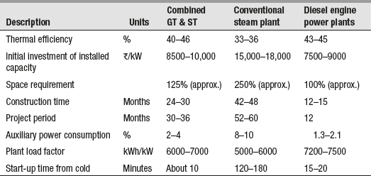
Table 13.1 makes a brief comparison of different types of captive power plants (combined gas turbine and steam turbine, conventional steam plant and diesel engine power plant).
It is evident from the table that captive diesel plant has a distinct edge over the other two types of plants in terms of thermal efficiency, capital cost, space requirements, auxiliary power consumption, plant load factor, etc.
Table 13.1 Comparison of Different Types of Captive Power Plants
13.4 PLANT LAYOUT WITH AUXILIARIES
Figure 13.6 show general layout of a Diesel Engine plant. The essential components of (diesel engine plant) are

Fig. 13.6 General Layout of DG Plant
- Engine: It is the main component that develops required power. The engine is directly coupled to the generator.
- Air filter and supercharger: Air filter removes the dust from the air before it enters the engine. Supercharger increases the pressure of air at engine inlet and hence increases engine power. They are usually driven by the engines.
- Exhaust system: The system includes silencers and connecting ducts. As the exhaust gases have higher temperatures, heat of exhaust gases is utilized for heating the oil or air supplied to the engine.
- Fuel system: It contains the storage tank, fuel pump, fuel transfer pump, oil strainers and heaters. The amount of fuel supplied depends on the load on the plant.
- Cooling system: The system includes water circulating pumps, cooling towers or spray ponds and water filtration or treatment plant. The purpose of cooling system is to ensure the life of the cylinder by extracting the heat developed from the engine cylinder walls and hence keeping the temperature within the safer range.
- Lubrication system: The system includes oil pumps, oil tanks coolers and connecting pipes. The system reduces friction between the moving parts and hence reduces wear and tear.
- Starting system: The system includes starting aides such as compressed air tanks. The tank supplies compressed air to start the engine from cold.
- Governing system: The governing engine maintains constant speed of the engine irrespective of load on the plant. This is done by varying the fuel supplied to the engine.
13.5 FUEL SUPPLY SYSTEM
Diesel engine fuel injection systems can be divided into two basic types:
1. Air injection
In this system, the fuel valve is connected to a high-pressure air line fed by a multistage air compressor driven by the engine. The pressure of air may be about 60–70 bar. The blast air sweeps the fuel along with it when the fuel valve is opened. Thus, a well-atomized fuel spray is sent to the combustion chamber.
2. Solid injection
In this system, fuel is directly injected into the combustion chamber without primary atomization. The method is also known as airless mechanical injection. The system consists of a pressurizing unit (fuel pump) and an atomizing unit (fuel injector). The high-pressure diesel is sprayed into the engine cylinder by the fuel injector.
Figure 13.7 shows the sectional view of Bosch fuel injection pump. It consists of a barrel with reciprocating plunger inside it driven by a camshaft. The plunger has a constant stroke and is single acting. A very small clearance of about two to three thousandths of a millimetre is provided between the pump barrel and the plunger. This arrangement provides a perfect sealing without any leakage even at very high pressures and low speeds. The pump barrel has two radially opposing ports known as inlet port and spill port or bypass port. A vertical channel extending from the top of the plunger to an annual helical groove is provided on the upper part of the plunger. It varies the quantity of fuel delivered per stroke. The top edge of the upper end is milled in the form of a helix. A spring-loaded delivery valve is provided at the top of the barrel. The position of the helical groove with respect to the spill port is changed by rotating the plunger with the rack or control rod. By moving the rack, the quantity of fuel injected can be varied from zero to that demanded at full load.

Fig. 13.7 Bosch Fuel Injection Pump
3. Operation
During the delivery stroke, a cam raises the plunger upwards and a plunger return spring brings it back to BDC position. When the plunger is at the bottom of its stroke, fuel starts flowing into the barrel through the inlet port. Fuel fills the space above the plunger in the vertical groove and in the space between the helix.
When the plunger starts moving upwards, some amount of fuel enters the barrel as the inlet ports are uncovered. Further movement of the plunger upwards covers both the inlet and spill ports and the trapped fuel gets compressed. Due to high pressure, fuel is forced through the delivery valve and enters the injector which injects fuel into the combustion chamber. The injection process continues till the end of the upward stroke and stops when the lower end of the helix uncovers the spill port. As soon as spill port uncovers, the fuel pressure in the barrel drops suddenly due to the flow of fuel back to the suction chamber through the vertical channel. Injection process ends as both spring-loaded injector valve and spring-loaded delivery valve are suddenly closed. Plunger movement controls the quantity of oil delivered.
Figure 13.8 shows a typical fuel system used in diesel plants. The fuel oil may be delivered at the plant site by trucks, railroad tank cars or barge and tankers. From tank truck, the delivery is done using the unloading facility to main storage tanks. This fuel is then transferred by pumps to small service storage tanks known as engine day tanks. The main flow is ensured by arranging the piping equipment with the necessary heaters, by passes, shut offs, drain lines, relief valves, strainers and filters, flow meters and temperature indicators. The actual flow depends on type of fuel, engine equipment, size of the plant, etc. The tanks should contain manholes for internal access and repair, fill lines to receive oil, vent lines to discharge vapours, overflow return lines for controlling oil flow and a suction line to withdraw oil. Coils heated by hot water or steam reduce oil viscosity, which lower pumping power needs.


Fig. 13.8 System of Fuel Storage for a Diesel Power Plant
The minimum storage capacity of at least a month's requirement of oil is generally kept in bulk. However, when the advantages of seasonal fluctuations in cost of oil are to be availed, it may be necessary to provide storage for a few months’ requirements. Day tanks supply the daily fuel needs of engines and are placed at a height so that oil may flow to engines under gravity.
The fuel oil supply system operation would be satisfactory if the following points are taken care of:
- Provisions for cleanliness and for changing over of lines during emergencies.
- Provisions for tight pipe joints in all suction lines.
- Keep all oil lines under air pressure with the joints tested with soap solution. Small air leaks into the line can be the source of operating difficulties and are hard to rectify once the plant is in operation.
- Flush the piping between filter and the engine thoroughly by oil before being first placed in service.
- Due importance should be given for cleanliness in handling bulk fuel oil. Dirt particles will ruin lap of injection pumps or plug the injection nozzle orifices. Thus, high-grade filters are of great importance to the diesel oil supply system.
13.5.1 Fuel Injection System
Fuel injection system is the heart of the diesel engine. In an injection system, very small quantity of fuel must be measured out, injected, atomized and mixed with combustion air. The mixing problem becomes more difficult, the larger the cylinder and faster the rotational speed. However, special combustion arrangements such as pre-combustion chambers, air cells, etc., are necessary to ensure good mixing. Engines driving electrical generators have lower speeds and simple combustion chambers.
Functions of a fuel injection system are as follows:
- Filter the fuel
- Meter or measure the correct quantity of fuel to be injected
- Properly time the fuel injection
- Control the rate of fuel injection
- Atomize or break-up the fuel into fine particles
- Properly distribute the fuel in the combustion chamber
The injection systems especially the parts that are actually manufactured with great accuracy meter and inject the fuel. Some of the tolerances between the moving parts are so small (of the order of 1 μ) that they require special attention during manufacture. Hence, the injection systems are costly.
13.5.2 Types of Fuel Injection Systems
Most commonly used fuel injection systems in diesel power station are as follows:
- Common rail injection system
- Individual pump injection system
- Distributor
Atomization of fuel oil can be done by (i) air blast and (ii) pressure spray. In the olden days, engines used air fuel injection at about 70 bar, which was sufficient not only to inject the oil, but also to atomize it for a rapid and thorough combustion. The expense of providing an air compressor and tank led to the development of ‘solid’ injection, using liquid pressure of between 100 and 200 bar, which is sufficiently high to atomize the oil it forces through spray nozzles.
1. Common rail injection system
Two types of common rail injection systems are shown in Figure 13.9 and 13.10, respectively.

Fig. 13.9 Common Rail Injection System Using a Single Pump

Fig. 13.10 Controlled Pressure System
In this case, a single pump supplies high-pressure fuel to header. A relief valve holds pressure constant. The control wedge adjusts the lift of mechanical operated valve to set the amount and time of injection.
Figure 13.10 shows a controlled pressure system. It has a pump that maintains set head pressure. Pressure relief and timing valves regulate injection time and amount. Spring-loaded spray valve acts merely as a check.
2. Individual pump injection system
An individual pump injection system is shown in Figure 13.11. In this system, an individual pump cylinder connects directly to each fuel nozzle. Pump meters charge and control injection timing. Nozzles contain a delivery valve that is actuated by the fuel oil pressure.

Fig. 13.11 Individual Pump Injection System
3. Distributor system
Most commonly used distributor system is shown in Figure 13.12. In this system, the fuel is metered at a central point. A pump pressurizes, meters the fuel and times the injection. The fuel is then distributed to cylinders in correct firing order by cam-operated poppet valves that open to admit fuel to the nozzles.

Fig. 13.12 Distributor System
13.6 SUPER CHARGING
It is well known that the power output of an engine increases with an increase in amount of air in the cylinder at the beginning of compression stroke. This is because air allows burning more quantity of fuel. Supercharging is a process that helps to increase the suction pressure of the engine above atmospheric pressure and the equipment used for this purpose is known as supercharger.
The advantages of supercharged engines are as follows:
- Power increase: By supercharging the engine, the engine output can be increased by 30–50 per cent at the same speed of the engine.
- Fuel economy: The combustion in supercharged engine is better as it provides better mixing of the air and fuel than un-supercharged engine. Hence, the specific fuel consumption of a supercharged engine is less than a natural aspirated engine. The thermal efficiency of a supercharged engine is also higher.
- Mechanical efficiency: The mechanical efficiency of a supercharged engine is better than a natural aspirated engine at the same speed. This is because the power increase due to supercharging increases faster than the rate of increase in friction losses.
- Scavenging: With the increase in supercharged pressure, the scavenging action is better in two-stroke supercharged engines as compared to naturally aspirated engines, because the quantity of residual gases is reduced.
- Knocking: Supercharging reduces the possibility of knocking in diesel engines because delay period is reduced with an increase in supercharged pressure. Actually, supercharging results in smoother running of the engine. It has been found that four-stroke engines are more easily adaptable to supercharging than two-stroke engines.
Due to the number of advantages of supercharging mentioned above, modern diesel engines used in diesel plant are generally supercharged. By supercharging, the size of the engine is reduced for a given output and consequently the space requirements and civil engineering works also reduced.
The Superchargers that are considered for diesel power plants are positive displacement type, centrifugal type and exhaust turbocharger. The selection depends upon its relative merits for a particular situation. Figure 13.13 shows a typical turbocharged engine.

Fig. 13.13 Working of a Turbo-Charged Engine
A turbocharger is used to force air/fuel mixture into an engine at a pressure greater than the natural atmospheric pressure. The exhaust coming out of the engine is pushed through a turbine, mounted on a shaft, which in turn spins an air compressor. The compressor draws air in and blows it into the inlet manifold, and generates the boost. Forcing the air/fuel mixture into an engine allows it to burn more fuel and generate more power without changing engine capacity. When the air is compressed (with a turbo) it gets hotter. As hotter air contains less oxygen than cooler air, less oxygen is available to burn extra fuel going into the engine.
13.7 METHOD OF STARTING DIESEL ENGINES
The SI engines used for power generation in DG plants are usually small in size, which use compression ratio from 7 to 11. Hand and electric motor (6–12V, DC) cranking are generally used to start the engine.
The CI engines use very high compression ratios from 20 to 22 and hence it is difficult to hand crank the engine. Hence, some mechanical cranking systems are used.
1. Compressed air system
In this system, shown in Figure 13.14, air at a pressure of 20–30 bar is supplied from an air tank at the engine inlet through intake manifold. In the case of multi-cylinder engine, compressed air enters one or more of the engine cylinders and forces down the piston to turn the engine shaft. During the meantime, suction stroke of some other cylinder takes place and the compressed air pushes this cylinder and causes the engine shaft to rotate. Gradually the engine gains momentum and by supplying the fuel engine starts running.

Fig. 13.14 Compressed Air System
2. Electric starting
An electric starting system is shown in Figure 13.15. It consists of an electric motor driving a pinion, which engages a toothed rim on engine flywheel. Electric supply for the motor is made using a small electric generator driven by the engine. A storage battery of 12–36 V is used to supply power to the electric motor. The electric motor disengages automatically after the engine has started.

Fig. 13.15 Electric Starting System
The starting motor for diesel and gasoline engines operates on the same principle as a direct current electric motor. The motor is designed to carry extremely heavy loads but, because it draws a high current (300–665 A), it tends to overheat quickly. To avoid overheating, the motor should not be run for more than the specified amount of time, usually 30 seconds. A time lag of 2 or 3 min is essential before using it again. The starting motor is located near the flywheel. When the starting switch is closed, the drive gear on the starter meshes with the teeth on the flywheel .The drive mechanism (1) transmits the turning power to the engine when the starting motor runs, (2) disconnects the starting motor from the engine immediately after the engine has started and (3) provides a gear reduction ratio between the starting motor and the engine. The drive mechanism disengages the pinion from the flywheel immediately after the engine starts to avoid any damage, since this engaged position may increase the motor shaft speed to 22,500–30,000 rpm as against the engine speed of 1500 rpm.
3. Hydraulic starting systems
Several types of hydraulic starting systems are in use for engines. A typical hydraulic starting system is shown in Figure 13.16. In general most systems consist of a hydraulic starting motor, a piston-type accumulator, a manually operated hydraulic pump, an engine-driven hydraulic pump and a reservoir for the hydraulic fluid. Hydraulic pressure is provided in the accumulator by a manually operated hand pump or from the engine-driven pump when the engine is operating. By operating the starting lever, the control valve allows hydraulic oil (under pressure of nitrogen gas) from the accumulator to pass through the hydraulic starting motor, and cranks the engine. When the starting lever is released, spring action disengages the starting pinion and closes the control valve. This stops the flow of hydraulic oil from the accumulator. To protect the starter from the high speeds of the engine, an overrunning clutch is used. The hydraulic starting system is used on some smaller diesel engines.

Fig. 13.16 Hydraulic Starting System
4. Starting by auxiliary engine
In this method, a small petrol engine is connected to the main engine through clutch and gear arrangement. The clutch is disengaged and the petrol engine is started by hand. Then the clutch is gradually engaged and the main engine is cranked for starting. Clutch is disengaged automatically when the main engine is started.
13.8 COOLING AND LUBRICATION SYSTEM FOR THE DIESEL ENGINE
Cooling and lubrication systems form an essential component of diesel engine plants. An efficient cooling and lubrication system not only improves the plant efficiency, but also ensures longer plant life. Given its importance, both of these systems are discussed hereunder.
13.8.1 Engine Cooling System
During the process of converting the thermal energy to mechanical energy, high temperatures are produced in the cylinders of the engine as a result of combustion. A large portion of heat from the products of combustion is transferred to the cylinder head and walls, piston and valves. This excess heat if not carried away by an efficient cooling system will damage the engine.
Necessity of engine cooling: Engine cooling is necessary for the following reasons:
- The maximum operating temperature of lube oil ranges from 160°C to 200°C. If the temperature exceeds this limit, lube oil deteriorates and even might evaporate or burn. This may result in damaging of piston and cylinder surfaces or piston seizure.
- Due to higher engine temperature, the strength of the materials used for various engine parts decreases. This may result in excessive thermal stresses due to uneven expansion of various engine parts and result in cracking.
- Hot engine parts result in hot exhaust valve, which causes pre-ignition and knocking.
- Due to higher engine temperature, volumetric efficiency and power output of the engine reduces.
Two basic systems used for cooling the engine are
1. Air cooling
In this system, atmospheric air is circulated around the engine cylinder to dissipate the excess heat. Heat transfer area is increased by providing fins on the cylinder and cylinder head and air is passed over them. Air cooling is used for small engines and aircraft engines. Using the fins increases the heat transfer surface by about 5–10 times its initial value. Figure 13.17 shows a sectional view of an engine cylinder using fins. As maximum temperature exists near the exhaust valve and cylinder head, more fins are required here to dissipate heat.

Fig. 13.17 Air Cooling System
The fins may be cast integral with the cylinder and cylinder head or may be fixed separately to the cylinder block. The number of cast fins may be 2–4 in number per centimetre or 4–6 fins per centimetre in case of machined fins. The spacing between the fins is limited to 2–5 mm and height of the fin varies from 20 to 50 mm.
2. Water cooling
In this system, the cylinder and cylinder head are enclosed in a water jacket. The water jacket is connected to a radiator or heat exchanger normally at the front end of the vehicle. Water is made to circulate through the water jacket, which cools the engine. The hot water returns to the radiator where it exchanges heat with atmospheric air. The cold water is again re-circulated.
Water cooling is used for bigger engines such as cars, buses, trucks, etc.
High operating temperature existing in the engine may disintegrate the lube oil film on the cylinder liners resulting in warping of valves and piston seizer, if the engine is not cooled properly. Thus, proper cooling of the engine is necessary to increase engine life. This is done by controlling the exit temperature of cooling water. If the exit temperature is too low, lube oil will not spread over the piston and the cylinders resulting in wear and tear. If it is too high, the lube oil burns and disintegrates. The exit temperature of cooling water is thus limited to 70°C. As constant flow rate of cooling water increases the exit temperature of cooling water with increased load, flow regulation of water is desirable to control the same.
The hot jacket water from the engine is passed through the coolers (hot well) where it is cooled with the help of raw water. The raw water is cooled in the cooling towers using either natural draft or forced draft air circulation. The sensible heat of water is transferred to air. In addition, the latent heat of evaporation of water vaporized is the main source of heat transfer. The degree of cooling action is limited by the vapour that can be absorbed before the air reaches saturation humidity at its leaving temperature. As the circulation of water is concerned, the cooling systems are generally divided into two types.
(i) Open- or single-circuit system
In this system shown in Figure 13.18, pump draws water from cooling pond and forces it into the main engine jackets. Water, after circulating through the engine, returns to the cooling pond. The engine jacket is subjected to corrosion because of the dissolved gases in the cooling water.

Fig. 13.18 Open- or Single-Circuit System
Figure 13.19 shows a closed or double circuit system.
(ii) Closed- or double-circuit system
In this system, raw water is made to flow through a heat exchanger when it takes up the heat of jacket water and returns back to the cooling pond or tower.

Fig. 13.19 Closed- or Double-Circuit System
About 25–35 per cent heat is lost by cooling water, which is known as jacket water loss. The rate of flow of water should be adjusted to maintain outlet cooling water temperature to 60°C and rise in temperature of cooling water is limited to 11°C. Water used for cooling should be free from impurities. Even though cooling by water is uniform, it poses a problem in cold weather. Cooling efficiency is reduced due to scaling in pipes, jackets and radiator. Engine efficiency is affected as some power is utilized to drive the water pump and radiator fan. This type of cooling system eliminates internal jacket corrosion, but the corrosion may exist in the raw water circuit.
13.8.2 Lubrication System
Due to the presence of friction, wear and tear of the engine parts takes place reducing the engine life. The lubricant introduced forms a thin film between the rubbing surfaces and prevents metal to metal contact. The various parts that require lubrication are cylinder walls and pistons, crank pins, gudgeon pins, big end and small end bearings, etc. The maintenance of proper lubrication system for all moving parts is an important problem in the operation of an IC engine.
The purpose of lubrication are (i) to reduce the power required to overcome friction, (ii) to increase the power output and (iii) to increase the engine life. Improper lubrication results in the breakdown of the lubricating films, causing piston seizure and serious damage to the engine.
Two basic systems used for engine lubrication are as follows:
1. Wet sump
In the wet sump system, the bottom of the crankcase contains an oil pan or sump which serves the purpose of an oil supplying tank or reservoir tank, or oil cooler. Oil dripping from the cylinders and bearings flows by gravity back into the wet sump where it is picked up by a pump and re-circulated through the engine lubrication system (Figure 13.20).

Fig. 13.20 Wet Sump Lubrication System
The types of wet sump systems generally used are (i) splash and circulating pump (force feed) system, (ii) force-feed system and (iii) full force-feed system.
2. Dry sump
In this dry sump system, oil is supplied from an external tank. Oil drips from the cylinders and bearings into the sump. Oil is removed from the sump and passed back to the external tank through a filter. As the sump pump capacity is greater than oil pump capacity, oil is prevented from accumulating in the engine base (Figure 13.21).

Fig. 13.21 Dry Pump Lubrication System
Lubrication may be achieved in different forms: Full pressure lubrication, mechanical, force feed lubrication or gravity circulation from an overhead tank. Some of the lubrication systems are explained below.
(i) Splash and force-feed lubrication system
In a splash and force-feed lubrication system (Figure 13.22), oil is delivered to some parts by means of splashing and other parts through oil passages under pressure from the oil pump. In this system, the oil from the pump entering the oil galleries flows to the main bearings and camshaft bearings. The main bearings have oil-feed holes or grooves that feed oil into drilled passages of the crankshaft. The oil flows through these passages further to the connecting rod bearings and from there through holes drilled in the connecting rods to the piston-pin bearings.

Fig. 13.22 Splash and Force-Feed Lubrication System
Cylinder walls are lubricated by splashing oil thrown off from the connecting-rod bearings. In some engines, small troughs are provided under each connecting rod that are kept full by small nozzles, which deliver oil under pressure from the oil pump. As engine speed increases, these oil nozzles deliver an increasingly heavy stream, powerful enough to strike the dippers directly. This generates a much heavier splash so that adequate lubrication of the pistons and the connecting-rod bearings is provided. In an overhead valve engine, the upper valve train is lubricated by pressure from the pump.
(ii) Force-feed lubrication system
In a force-feed lubrication system (Figure 13.23), oil is forced by the oil pump from the crankcase to the main bearings and the camshaft bearings. Unlike the splash and force-feed lubrication system, the connecting-rod bearings are also fed oil under pressure from the pump.

Fig. 13.23 Force-Feed Lubrication System
Oil passages drilled in the crankshaft lead oil to the connecting-rod bearings. The passages deliver oil from the main-bearing journals to the rod-bearing journals either through holes or through annular grooves. The holes line up once for every crankshaft revolution. In the case of annular grooves in the main bearings, oil can be fed constantly into the hole in the crankshaft.
The pressurized oil that lubricates the connecting-rod bearings also lubricates the pistons and walls by squirting out through strategically drilled holes. This lubrication system is used in all engines that are equipped with semi-floating piston pins.
(iii) Full force-feed (pressure) lubrication system
In a full force-feed lubrication system, an oil pump supplies lubricating oil to many parts of the engine through duct system and to the crank shaft through drilled holes. The cylinder walls are lubricated by oil mist that is slung outward from the connecting rod bearings or by splash of rod ends into oil pools. This system lubricates the main bearings, rod bearings, camshaft bearings and the complete valve mechanism. In addition, lubrication of the pistons and the piston pins is also enabled under pressure by holes drilled throughout the length of the connecting rod, creating an oil passage from the connecting rod bearing to the piston pin bearing. This passage not only feeds the piston pin bearings but also provides lubrication for the pistons and cylinder walls. This system is used in all engines that are equipped with full-floating piston pins (Figure 13.24).

Fig. 13.24 Full Force-Feed (Pressure) Lubrication System
13.8.3 Filters, Centrifuges and Oil Heaters
1. Filters
The air cleaner or filter filters the incoming air. It also muffles the resonation (i.e. dampens the noise) of the swirling incoming air. The location of the air cleaner depends on the available space and the hood design.
An air filter performs the following functions:
- It filters incoming air and removes impurities present in it.
- During back firing of the engine, it acts as a flame arrester.
- It acts as a silencer for the carburetion system by reducing the engine induction noise.
The filters used may be classified depending on the dust type and dust concentrations in the air.
(i) Oil impingement type
It consists of a frame filled with crimped (pressed into small folds or corrugated) wire or metal shavings (thin particles). These are coated with a special oil so that air passing through the frame breaks up into smaller filaments when it comes into intimate contact with the oil. The oil can seize and hold any dust particles being carried by air. The efficiency of this filter drops progressively when in service. Hence, it should be refreshed periodically by removing, washing and re-oiling.
(ii) Oil-bath type
In this type of cleaner, the air is swept over or through a pool of oil. The dust particles become coated to the oil. The air is then passed through the filter, which retains the oil-coated dust particles. Figure 13.25 shows an oil bath-type oil filter containing a filter element saturated with oil. Oil is contained in a separate oil pan. Air from the atmosphere enters through the circumferential gap 1 and takes a turn at corner 2. This movement leaves large particle impurities present in air. Air then passes over the filter element through the oil surface. The clean air then passes through the passage 3.

Fig. 13.25 Oil Bath-Type Air Cleaner
(iii) Dry type
It is made up of cloth, felt, glass, wool, etc. The filters catch dirt by causing it to cling to the surface of the filter material. The capacity of such filters drops progressively when they are in use. The cleaning is done based on the amount of air used by the engines and dust concentrations in it.
Figure 13.26 shows a light duty air cleaner. It consists of a bonded cylindrical cleaning element made of cellulose fibre material placed over a fine mesh screen that provides strength. The sides of the element are sealed against dust. Air passes through the element leaving any impurities present outside it.

Fig. 13.26 Light Duty Air Cleaner (Dry)
2. Centrifuges and oil heaters
The complete lubrication system usually includes the following auxiliaries: Pump, oil cleaners, oil coolers, storage and sump tanks, gauges and safety devices. As oil passes through the lubrication cycle, it accumulates impurities in the form of carbon particles, water and metal scrap. For continuous reliable operation, attention should be given to oil cleaning.
For this purpose, filters with centrifuges or chemical action have been employed. Mechanical filters include cloth bags, wool, felt pads, paper discs and cartridge of porous material.
Rough cleaning of oil can be done by passing high-speed centrifuges for final cleaning. Centrifuging can be done by periodic centrifuging of the entire lubricating oil or by continuous cleaning of a small fraction of it by splitting the oil from main flow and returning back to the main stream. Oil should be heated before passing it through the centrifuge.
Oil should be cooled before supplying it to the engine. As heat is developed due to friction between the moving parts, the cooling is done by using water from the cooling tower (Figure 13.27).

Fig. 13.27 Continuous Centrifuging System
13.9 INTAKE AND EXHAUST SYSTEMS
Intake and exhaust systems used in diesel engines ensure smooth functioning of the engine. As diesel engines draw in air only, speed and power are controlled by the amount of fuel injected at the end of the compression stroke. For two-stroke diesel engines, a blower is used for induction of air and to improve scavenging. An exhaust system must reduce engine noise and discharge exhaust gases safely away from the engine. An efficient exhaust system can improve engine performance. Both these systems and their essential components are discussed in this section.
13.9.1 Intake System
The primary components of the automotive intake system are Intake manifold, throttle body and air induction components such as air cleaner and ducting.
The intake manifold is normally made of an aluminium alloy and is attached to the cylinder head. Its construction and design depends on its application. The intake manifold can accommodate a throttle body Injection unit and the mixing of the air/fuel mixture is done at the manifold base. The butterfly shaft connected to the throttle cable controls the airflow through the unit.
The air induction components consist of an air cleaner and housing, solid and flexible-duct tubing, and connectors. The air induction system draws in ambient air from the atmosphere. The inlet opening may be located in various positions under the hood.
1. Air cleaner
The air cleaner filters the incoming air. The air cleaner element may be manufactured from pleated paper, oil impregnated cloth or felt, or in an oil bath configuration. Another function of the air cleaner is to muffle the resonation (i.e. dampen the noise) of the swirling incoming air. The location of the air cleaner depends on the available space and the hood design.
2. Ducting
The ducting can be made of hardened plastic with flexible rubber couplings to absorb engine movement. These are usually secured in place by metal worm drive clamps.
Figure 13.28 shows a typical intake system of a diesel engine plant. A large diesel engine plant requires about 0.076 m3/min to 0.11 m3/min of air per kW of power developed. Air contains a lot of dust, hence if it is necessary to remove the dust content in the atmospheric air. The air system contains an intake manifold located outside the building with a filter to catch dirt that would otherwise cause excessive wear in the engine. If the atmospheric temperature is too low, engine misfires at low loads and hence it is necessary to install a heating element using exhaust gas. Occasionally, engine noise may be transmitted back through the air intake system to the outside air. In such cases, a silencer is provided between the engine the intake. It is a light weight steel pipe.

Fig. 13.28 Engine Intake System
13.9.2 Exhaust System
The primary components Figure 13.29 shows an engine exhaust system. The primary components of the exhaust system are exhaust manifold, engine pipe, catalytic converter, exhaust brackets, muffler and components such as the resonator and tail pipe.

Fig. 13.29 Engine Exhaust System
The exhaust system generally handles approximately 0.23 m3/min to 0.30 m3/min of gases per kW developed at the average exhaust temperature. Muffling of the exhaust noise is done by using silencers located outside the building. They may be of CI, steel, etc. A pipe or stack will extend vertically from the silencer outlet to carry the exhaust gases.
The following provisions should be made for the exhaust system:
- Silencing of the exhaust noise to the required degree.
- Discharge of the exhaust sufficiently high above the ground level.
- Water-cooled exhaust lines or special high-temperature materials for exhaust pipes.
- Modification to utilize the by-product heat.
- Isolation of engine vibration from building and muffler system by using flexible section of the exhaust pipe.
- Arrangement of the exhaust system to minimize the back pressure created by the exhaust system itself.
13.10 APPLICATION OF DIESEL POWER PLANT, ADVANTAGES AND DISADVANTAGES
The diesel electric power plants mainly find application in the following fields:
1. Peak load plant
The diesel plants are used in combination with thermal or hydro-electric plants as peak load plants. This plant is used only during peak load plant operation, as it can be started quickly and it has no standby losses.
2. Mobile plants or outdoor units
Mobile diesel plants mounted on skids or trailers can be used for temporary or emergency purposes such as for supplying power to large civil engineering works for supplementing electricity supply systems that are temporarily short of power. Mobile plants also find application in various other industries such as film, etc.
3. Standby units
Diesel plants are also used as a standby unit to supply part load when required. For example, this can be used with hydro-plant as a standby unit. If the water available is not sufficient due to reduced rainfall, a diesel station supplies power in parallel with hydroelectric station. The use is made temporarily till the water is available to take the full load.
4. Emergency plant
The plants can be used for emergency purposes where they act as standby units, normally idle. Whenever there is power interruption, these units are used. For example, they are used in situations when power failure may lead to financial loss or danger in key industrial processes, tunnel lighting and operating rooms of hospitals. They are also used for telecommunication and water supply under emergency conditions.
5. Nursery station
A ‘Nursery Station’ is used to supply power to a small town in the absence of main grid and which can be moved to another area once power from the main grid is available. This happens especially when the area is remote, not approachable or the extension of grid is not possible due to constructional difficulties.
6. Starting stations
The diesel units are used to run the auxiliaries for starting the large steam plants.
7. Central stations
Small supply central stations are used for commercial purposes and public utilities, for example cinema hall, hospital and municipalities, etc. The station capacity is generally small (5–10 MW). Before installation of such units, a thorough study is made on the cost of the plant and local conditions regarding the availability of fuel and water, space requirements and non-availability of the grid.
Advantages and disadvantages of diesel plants are as follows:
- It has no standby losses and can burn a fairly wide range of fuels.
- Manufacturing periods are short; therefore, plant expansion can be done just by adding the generating units of required size.
- Diesel plants can be fully automated with reasonably low capital costs, namely, for starting, synchronizing and shutting down diesel sets, to overcome scarcity of skilled labour.
- Maintenance can be simplified by the provision of easily replaceable assemblies of parts, thus enabling reconditioning to be undertaken away from generating plants.
- Can be installed in remote, cramped or difficult-to-access areas as the unit is compact, light weight and available in smaller capacity.
- The diesel plants can be located very near to the load centres, many times in the heart of the town.
- They can be employed in all climatic zones and they are very adaptable and can be easily extended to the given power requirements.
Machine sets are readily available as standard sets in the range of 500 kW to 40 MW.
- Due to its relatively low cost, it is possible to install a spare unit that can be kept as permanent standby.
- Operational reliability with high availability is ensured.
Disadvantages
- The diesel plants are not economical where fuel has to be imported.
- The noise is a serious problem in diesel plant.
- Selected types of fuels are required in diesel engines whereas there is more mobility in case of thermal plant.
- The lubrication cost is high.
13.10.1 Comparison with Stream Power Plants
- The diesel power plants are more efficient than steam power plants in the range of 150 MW capacity. The operating efficiency is high in the load range of 50–100 per cent of full load.
- The first cost diesel plants are lesser than steam plants for plant capacity up to about 7 kW. Above this capacity, the diesel cost rises rapidly while that of steam plants continues to fall.
- It can be quickly started up and brought into service (within 1 min).
- The cooling water required for the same capacity is considerably less in diesel plants than the thermal plant. The site of the thermal plant is dictated by the availability of cooling water in many cases, whereas diesel plant can be located without giving much importance to the availability of cooling water. The water ratio for thermal to diesel is approximately 50:1.
- The storage required for the fuel is considerably less than the thermal and it can be handled more easily.
- There is no problem of ash handling as there is practically no refuse.
- The space required for diesel plant is considerably less than thermal plant and, therefore, cost of foundation and buildings is less.
- A diesel engine lubrication system is more economical compared to a steam plant and permits the use of specially compounded cylinder lubricants that provide dramatic improvement in wear rates.
- A diesel engine plant layout is very simple compared with a thermal plant. They are easy to operate and control also.
- The unit capacity of diesel engine is considerably smaller than the thermal unit. The cost of unit increases with an increase in unit capacity for diesel plant. However, the cost of the unit goes on decreasing in case of thermal plant with an increase in unit capacity.
- The repair and maintenance costs of diesel plants are generally much higher than for steam plants. These costs are more or less fixed in the case of steam plants and more or less are proportional to output in the case of diesel plants.
- Life of 25–30 years is normal for thermal plant, whereas the life of diesel plant is hardly two to five years or less.
- The diesel plants are not suitable for continuous operation under overloads, whereas steam plants can work under 25 per cent overload continuously.
13.11 LAYOUT OF DIESEL PLANT
The layouts of diesel power plants for high-capacity (50 MW and above), medium-capacity (25–50 MW) and low-capacity plants are shown in Figure 13.30–13.32. Generally, in all three cases, the generating units are installed parallel with parallel centre lines. Sufficient space must be provided around various units for dismantling and repairing purposes. Fuel storage tanks may be located outside the building to avoid fire hazards. Some space should be left for future expansion. The engine room should be provided with sufficient ventilation. The plant must include many instruments for the guidance of operators to ensure reliability, economy and safety.

Fig. 13.30 Layout of Diesel Power Plant for High Capacity (50 MW and above)

Fig. 13.31 Layout of Diesel Power Plant for Medium Capacity (25–50 MW and above)

Fig. 13.32 Layout of Diesel Power Plant for Small Capacity
13.12 DIESEL ENGINE PERFORMANCE AND OPERATION
1. Power and mechanical efficiency
Power is the work done by the engine in unit time, which is the product of force and linear velocity. This can also be expressed in terms of product of engine torque and angular velocity. Torque measurement is done by a dynamometer and speed is measured using a tachometer as discussed earlier.
Power developed by the engine at the shaft output is called brake power, denoted by BP.
If T = torque developed, kN m
W = load applied, kN
R = radius of brake drum, m
N = engine speed, rps
then, brake power is given by
BP = 2π NT kW
The total power actually developed on the pistons of the engine is called indicated power, denoted by IP. This indicated power is always greater than brake power, because a part of the indicated power is spent in overcoming friction of the bearings, pistons and other mechanical parts of the engine. Some of this power is also spent in induction of fuel air charge and exhaust gases delivery. Hence, the difference between the indicated power and brake power is known as friction power, denoted by FP.
Thus, IP = BP + FP
The ratio of power delivered by the engine (BP) to the total power developed within the engine (IP) is known as mechanical efficiency, denoted by ηm.
ηm = ![]() =
= ![]() =
= ![]()
For a variable speed engine, both IP and BP increase as speed increases. As BP is lower than IP, both graphs generally curve slightly towards the top as shown in Figure 13.33.

Fig. 13.33(a) Variation of BP and IP vs. Speed

Fig. 13.33(b) Variation of IP vs. BP
For a constant speed engine, if the IP is plotted against BP a nearly straight line of increasing value will occur. The graph passes through the IP axis with a positive value, BP being 0.
The mechanical efficiency graph appears similar to both variable and constant speed engines as shown in Figure 13.34. Efficiency reaches a maximum at one point and then starts decreasing due to increased friction and engine overloading. For a variable speed engine, mechanical efficiency is plotted against speed and for a constant speed engine mechanical efficiency is plotted against BP.
Fig. 13.34 Variation of BP vs. Mechanical Efficiency

2. Mean effective pressure
Mean effective pressure (MEP) is a hypothetical pressure acting on the piston throughout the power stroke. It is denoted by pm.
Figure 13.35 shows a p–V diagram of a four-stroke IC engine. Positive area refers to the work output whereas negative area refers to the work input. In general, the negative area is very small compared to positive area and can be neglected. In case of a two-stroke engine, only positive area is present.

Fig. 13.35 p–V Diagram of a Four-Stroke IC Engine
MEP
pm = ![]()
pm = ![]()
Indicated MEP can be defined as the theoretical constant pressure that can be imagined to be exerted during each power stroke of the engine to produce power equal to indicated power, IP. It is denoted by pim.
If pim = indicated MEP, kN/m2
L = stroke length, m
A = area of the piston, m2
N = rotational speed, rps
n = number of revolutions required for each power stroke delivered per cylinder
= 2 for four-stroke engine; = 1 for two-stroke engine
x = number of cylinders in the engine
then IP = ![]() kW
kW
Brake MEP can be defined as the theoretical constant pressure that is exerted during each power stroke of the engine to produce power equal to indicated power. It is denoted by pbm.
The difference between indicated MEP and brake MEP is known as friction MEP. It is denoted by pfm.
Thus,
pim = pbm + pfm
and ηm = ![]()
3. Torque and MEP
We have BP = 2π NT = ![]()
Hence, torque is given by
T = ![]()
The above equation shows that torque and MEP are related by engine size. For larger engine size at constant MEP, torque increases. The parameter MEP shows how well the engine is using its size (displacement) to produce work. Hence, engines can be compared based on MEP because they cannot be compared on their relative brake powers, as brake power depends on both engine size and speed. Thus, while designing the engine, high MEP is always preferred.
Figure 13.36 shows the variation of torque versus speed and BP for a variable speed and a constant speed engine. For a constant speed engine, torque increases proportionately with BP and the graph is a straight line.

Fig. 13.36 Torque vs. Speed and BP
4. Specific fuel consumption
Specific fuel consumption (sfc) is defined as the amount of fuel consumed per hour per unit power developed. It is denoted by sfc. It is a comparative parameter that shows how efficiency of an engine is converting fuel into work.
Thus, sfc = ![]()
If the specific fuel consumption is based on brake power (BP) developed, then it is known as brake-specific fuel consumption, bsfc.
If the specific fuel consumption is based on indicated power (IP), then it is known as indicated specific fuel consumption, isfc.
Figure 13.37 shows the variation of specific fuel consumption with engine speed at full throttle of an SI engine.

Fig. 13.37 Variation of sfc vs. Speed
5. Air–fuel (AF) and fuel–air ratio (FA)
AF ratio is defined as the ratio of mass flow rate of air to the mass flow rate of fuel.
AF = ![]()
AF = ![]()
FA ratio is the reciprocal of AF ratio. It affects the phenomenon of combustion and determines the flame propagation velocity, heat released, maximum combustion temperature and completion of combustion.
Chemically correct FA ratio is also known as stoichiometric FA ratio. The ratio of actual FA ratio to stoichiometric FA ratio is known as relative FA ratio. Thus,
Relative FA ratio = ![]()
6. Volumetric efficiency
The volumetric efficiency of an engine is defined as the ratio of actual mass of air inducted by the engine during the intake (suction) stroke to the theoretical mass of air that should have been inducted by filling the piston displacement volume with air at atmospheric pressure and temperature. It is denoted by ηv Thus,
Volumetric efficiency = ηv = ![]()
In supercharged engines, the volumetric efficiency can be lesser than or greater than unity.
7. Specific output
Specific output is defined as the brake power developed per unit volume of piston displacement.
Specific output = ![]()
= ![]()
= constant × pbm × N
Thus, specific output can be increased by either increasing engine speed or increasing brake MEP. The former method leads to increased mechanical stresses in engine parts whereas the latter leads to more load on the engine cylinder.
8. Thermal efficiency
Thermal efficiency of the engine is defined as the ratio of output to the energy supplied by the combustion of fuel. If the output is based on the indicated power, it is known as indicated thermal efficiency, and if the output is based on brake power, it is known as brake thermal efficiency. Thus,
Indicated thermal efficiency,
ηi = ![]()
ηi = ![]()
Brake thermal efficiency,
ηb = ![]()
ηb = ![]()
where mf = mass or volume of fuel, kg/s or m3/s and CVf = calorific value of fuel, kJ/kg or kJ/m3
9. Relative efficiency
The relative efficiency or efficiency ratio is the ratio of the actual efficiency of the engine to the theoretical efficiency of the engine.
Relative efficiency,
ηr = ![]()
The variation of thermal efficiency versus engine speed is shown in Figure 13.38.

Fig. 13.38 Variation of Thermal Efficiency versus Speed
10. Heat balance
Heat balance gives an idea about the amount of heat supplied and the amount of heat utilized in the system. It gives useful information about the performance of the engine. The heat balance calculations are done generally either on minute basis or hour basis.
Heat supplied by the engine
Heat supplied by the engine by burning mf kg of fuel is given by
QA = mf × CVf
where CVf is the lower calorific value of the fuel.
Heat utilized by the system
- Heat equivalent of BP = BP × 60 kJ/min
- Heat lost to cooling water
Let, mw = Mass flow rate of water, kg/min
Cpw = Specific heat of water, kJ/kg K
Two = Outlet temperature of water, °C
Twi = Inlet temperature of water, °C
then heat lost to cooling water is
Qw = mw Cpw (Two − Twi)
- Heat lost to exhaust
Let
mg = mass flow rate of exhaust gas, kg/min
Cpg = specific heat of gas
Tge = exhaust gas coming out of the engine, °C
Ta = ambient temperature, °C
then heat carried away by exhaust gases.
Qg = mg Cpg (Tge − Ta) kJ/min
- Heat lost due to radiation, convection and leakage of gases is known as unaccounted heat.
Unaccounted heat loss = QA − [(a) + (b) + (c)]
The results are tabulated and compared on percentage basis as shown below.

Notes: As the frictional heat will be dissipated in cooling water, exhaust gases, radiation and convection, it is not necessary to include heat lost due to frictional power FP. Measurement of heat lost due to cooling water and the heat lost to exhaust gases are carried out as explained earlier.
Figure 13.39 shows the performance of SI engines at constant speed and variable loads. The load can be varied by altering the throttle, and the speed is kept constant by resetting the dynamometer. Closing the throttle does not affect the temperature very much as the AF ratio is more or less constant and the gas temperatures in the cycle are too high. But this action reduces the cylinder pressure resulting in high loss to the coolant at low engine load. This is the reason why CI engines are better at part loads than SI engines.

Fig. 13.39 Performance of SI Engines at Constant Speed and Variable Loads
At low loads, efficiency is about 9–10 per cent and rises to about 25 per cent at full load. The loss to coolant is nearly double (60 per cent) at low loads as against full load (30 per cent). The exhaust temperature varies steadily but slowly with load. As mass flow rate of fuel into the engine is reduced, mass flow rate of exhaust gas is also reduced and percentage of loss of exhaust gas remains nearly constant. However, percentage loss to radiation has almost a threefold increase at low loads as compared with full load.
Figure 13.40 shows the performance of CI engine at constant speed but at variable load. Due to the higher compression ratio and more thermal efficiency of CI engine, the losses are less. The coolant losses are more at low loads and unaccounted losses due to radiation, etc., are more at high loads. The heat to exhaust is comparatively higher compared to SI engines. However, the useful work is comparatively higher at low loads, reaches maximum and slowly decreases when load is further increased.

Fig. 13.40 Performance of CI Engines at Constant Speed and Variable Loads
11. Performance of diesel power plant
Like other plants, diesel plants are also run at part load conditions. The part load performance of a diesel engine power plant such as specific fuel consumption, brake thermal efficiency and mechanical efficiency is shown in Figure 13.41. As the part load increases, engine characteristics, namely, the specific fuel consumption increases, whereas both the thermal and mechanical efficiencies decrease. However, these effects are not as predominant as in steam power plants.

Fig. 13.41 Performance of Diesel Power Plant
Example 13.1
From the data given below, draw a heat balance sheet for a single-cylinder, four-stroke oil engine.
Cylinder bore = 200 mm
Stroke = 350 mm
Gross mean effective pressure = 7 bar
Pumping mean effective pressure = 0.4 bar
Engine speed = 5 rev/s
Net brake load = 370 N
Brake drum radius = 1.2 m
Fuel used = 3 kg/h
Gross calorific value of oil = 44,000 kJ/kg
Mass of cooling water = 4 kg/min
Rise in temperature of cooling water = 36°C
Mass of air supplied = 1.4 kg/min
Temperature of exhaust gasses = 320°C
Room temperature = 17°C
Mean specific heat of dry gases = 0.75 kJ/kg K
Mass of exhaust gasses = 2 kg/min
Solution: Net mean effective pressure = Gross MEP − Pumping MEP
= 7 − 0.4
= 6.6 bar
Area of cylinder, A = ![]()
= 0.0314 m2
Indicated power, IP = ![]() ; x = 1; n = 2
; x = 1; n = 2
= ![]()
= 18.13 kW
Brake power BP = ![]()
= 2π × 5 × 370 × 10−3 × 1.2
= 13.95 kW
Heat in fuel supplied/minute QA = mf × CVf
= ![]() = 2200 kJ
= 2200 kJ
Heat equivalent to brake power/minute
= BP × 60 = 13.95 × 60
= 837 kJ
Heat equivalent to indicated power/minute
= IP × 60 = 18.13 × 60
= 1087.8 kJ
Heat in friction/minute
= IP − BP = 1087.8 − 837
= 250.8 kJ
Heat lost to jacket cooling water/minute
Qw = mw Cpw ΔT
= 4 × 4.186 × 36
= 602.78 kJ
Heat lost to dry exhaust gases/minute
Qg = mg × Cpg × (Tge − Ta)
= 2 × 0.75 (320 − 17)
= 454.5 kJ
Unaccounted heat due to radiation, etc.
= QA − (heat equivalent of BP + Qw + Qg)
= 2200 − (837 + 602.78 + 454.5)
= 305.72 kJ/min
The heat balance sheet is drawn by knowing the amount of heat supplied and the amount of heat utilized by the system.

Example 13.2
During a test on a four-stroke cycle oil engine the following data and results were obtained.
Speed of the engine = 360 rpm
Swept volume of cylinder = 12 liters
Effective brake load = 70 kg
Effective brake radius = 0.6 m
Mean height of indicator diagram = 20 mm
Indicator calibration = 28 kN/m2/mm
Fuel consumption = 0.0016 kg/s
Calorific value of fuel = 44,000 kJ/kg
Cooling water circulation = 0.10 kg/s
Cooling water outlet temperature = 68°C
Cooling water inlet temperature = 35°C
Specific heat capacity of water = 4.18 kJ/kg K
Energy to exhaust gases = 34 kJ/s
Determine the indicated and brake outputs and the mechanical efficiency. Draw up an overall energy balance in kJ/s and as a percentage.
Solution: Indicated mean effective pressure is given by
pim = 20 × 28 = 560 kN/m2
Hence, indicated power
IP = pim LAN × ![]() ; x = 1, n = 2
; x = 1, n = 2
Now,
swept volume of the cylinder = VS = LA
= 12 l
= 12 × 10−3 m3
Indicated power = 560 × 12 × 10−3 × ![]()
= 20.16 kW
Brake power = 2π NT
= (2π × 6 × 9.81 × 70 × 0.6) × 10−3
= 15.53 kW
Mechanical efficiency = ![]() = 77.03%
= 77.03%
Energy from fuel = Fuel consumption × Calorific value of fuel
= 0.0016 × 44,000
= 70.4 kJ/s
Energy to brake power = 15.53 kW = 15.53 kJ/s
Energy to coolant = mw × Cpw (Two − Twi)
= 0.10 × 4.186 (68 − 35)
= 13.81 kJ/s
Energy to exhaust (given) = 34 kJ/s
Energy to surroundings, etc. = Energy from fuel − [Energy to BP + Energy to coolant + Energy to exhaust]
= 70.4 − (15.53 + 13.81 + 34)
= 7.061 kJ/s
Energy balance can be tabulated

Example 13.3
In a trial of a four-cylinder, four-stroke petrol engine of 90 mm bore and 100 mm stroke, the net dynamometer load was 1400 N at a radius of 460 mm, when the speed was 2200 rpm. At the same speed and throttle opening, the engine required 4 kW to motor it with the ignition switched off.
- Calculate the mechanical efficiency and indicated mean effective pressure.
- During a 3 min run at this speed and power, the engine used 2.4 kg of petrol of calorific value 42,980 kJ/kg and 100 kg of cooling water with a temperature rise of 40°C.
Draw up a heat balance for the test in kJ/min.
Solution:
- Brake Power
Brake power, BP = 2π NT =

BP = 148.37 kW
Frictional power, FP = 4 kW
Indicated power = Brake power + Frictional power
= 148.37 + 4 = 152.37 kW
Mechanical efficiency =

=
 = 97.37%
Indicated mean effective pressure
pim =
 =
= 
= 32.66 bar
- Heat Input = Fuel consumption × Calorific value of fuel
=

= 34,384 kJ/min
Heat to jacket cooling water
= mwCpw ΔT =

= 5581.33 kJ/min
Heat equivalent to BP = 148.37 × 60 = 8902.2 kJ/min
Heat equivalent to IP = 152.37 × 60 = 9142.2 kJ/min
Heat equivalent to FP = 4 × 60 = 240 kJ/min
Heat to exhaust and radiation, etc. = 10,518.27 kJ/min
Heat balance for 1 min

Example 13.4
A six-cylinder four-stroke diesel engine of 34 cm bore and 38 cm stroke gave the following results during testing.
BP = 142 kW; N = 350 rpm; pm = 3.7 bar
mf = 44 kg/h; (CV)f = 44,800 kJ/kg; ma = 38 kg/min
mw = 60 kg/min; and cooling water temperature rise = 41°C
Piston cooling oil = 35 kg/min, Cp of oil = 2.1 kJ/kg K
Rise in cooling oil temperature = 28°C
Exhaust gas temperature = 190°C, ambient temperature = 20°C
Fuel contains 14 per cent H2 by mass and Cpg = 1.05 kJ/kg K
Partial pressure of water vapour carried in exhaust gases = 0.06 bar
Draw the heat balance sheet on minute basis and percentage basis. Find the specific fuel consumption at full load assuming mechanical efficiency as 0.6.
Solution: Indicated power of the engine,
IP = pim × L × A × N × ![]()
= 3.7 × 100 × 0.38 × ![]() × 0.342 ×
× 0.342 × ![]() ×
× ![]()
= 223.4 kW
Heat supplied = mf × CVf = ![]() × 44,800 = 32,853.33 kJ/min
× 44,800 = 32,853.33 kJ/min
Heat equivalent of BP = 142 × 60
BP = 8520 kJ/min
Heat lost to cooling water,
Qw = mw × Cpw × ΔT
= 60 × 4.186 × 41
Qw = 10,297.56 kJ/min
Heat lost to cooling oil,
Qo = (m × Cp × ΔT) oil
= 35 × 2.1 × 28
Qo = 2058 kJ/min
Heat lost to dry exhaust gases
Mass of exhaust gases,
m = ma + mf
= 38 + ![]() = 38.73 kg/min
= 38.73 kg/min
Mass of water vapour formed
![]()
= ![]() × 9 × 0.14 (1 kg of H2 forms 9 kg of H2O
× 9 × 0.14 (1 kg of H2 forms 9 kg of H2O
= 0.924 kg/min
Mass of dry exhaust gases
mg = m − ![]()
= 38.73 − 0.924
= 37.806 kg/min
Hence, heat lost to exhaust gases
Qg = mg × Cpg × (Tge − Ta)
= 37.806 × 1.005 × (190 − 20)
Qg = 6459.16 kJ/min
Heat carried away by water vapour
From steam tables at 0.06 bar, 190°C
h = 2860 kJ/kg
Heat carried away by water vapour
Qwv = 0.924 × 2860
Qwv = 2642.64 kJ/min
The heat balance sheet is prepared now on minute and percentage basis

Now, indicated thermal efficiency
= ![]()
= ![]()
= 0.396
= 39.6%
Mechanical efficiency and brake thermal efficiency are same at full load also.
BP at full load = 2 × 142 = 284 kW
At half-load condition
FP = IP − BP
= 223.4 − 142
= 81.4 kW
At full-load condition
FP = IP − BP
IP = BP + FP
= 284 + 81.4 = 365.4 kW
Hence, heat supplied
= ![]() =
= ![]()
= 55,363.64 kJ/min
Hence, specific fuel consumption at full load
bsfc = ![]()
= 0.261 kg/kWh
Example 13.5
The following observations were made during one hour test on a single-cylinder, four-stroke oil engine. Bore = 300 mm; stroke = 450 mm; mass of fuel used = 8.8 kg; calorific value = 41,800 kJ/kg; average speed = 200 rpm; mean effective pressure = 5.8 bar; brake load = 1860 N; mass of cooling water circulated = 650 kg; temperature rise = 22°C; diameter of brake drum = 1.22 m. Calculate (i) mechanical efficiency and (ii) brake thermal efficiency and (iii) draw the heat balance sheet.
Solution:
- Mechanical efficiency
Indicated power,
IP = pm × L × A × N × x = 1;
 n = 2
n = 2= 5.8 × 100 × 0.45 × (π/4) × 0.32 ×
 ×
× 
= 30.748 kW
Brake power,
BP = 2πNT
= 2πNW × R
= 2 × π ×
 × 1860 ×
  × 10-3
= 23.763 kW
Mechanical efficiency,
ηm =
 × 100 =
= 77.283%
- Brake thermal efficiency
ηBth =
 =
= 
= 0.2326 or 23.26%
- Heat balance sheet
Heat input from fuel
= mf × CVf
= 8.8 × 41,800
= 3,67,840 kJ/h
Heat equivalent of BP
= BP × 3600 = 23.763 × 3600
= 85,546.8 kJ/h
Heat lost to cooling water
Qw = mw × Cpw × ΔT
= 650 × 4.186 × 22
= 59,859.8 kJ/h
Heat lost to exhaust, radiation, etc.
= 3,67,840 − (85,546.8 + 59,859.8)
= 2,22,433.4 kJ/h
Heat balance sheet on hour basis

Example 13.6
During a test on a single-cylinder, four-stroke oil engine, the following observations are made: Bore = 30 cm; stroke = 45 cm; duration of trial = 1 h, total fuel consumption = 7.6 kg; calorific value of fuel = 45,000 kJ/kg, total revolutions made = 12,000; mean effective pressure = 6 bar, net brake load = 1.47 kN; brake drum diameter = 1.8 m, rope diameter = 3 cm; mass of jacket cooling water circulated = 550 kg; water enters at 15°C and leaves at 60°C; total air consumption = 360 kg; room temperature = 20°C; exhaust gas temperature = 300°C. Calculate (i) indicated and brake power and (ii) mechanical efficiency and (iii) draw the heat balance sheet on minute basis.
Solution:
- Indicated and brake power
Indicated power, IP = pm × L × A × N ×
 ; x = 1; n = 2
= 6 × 100 × 0.45 × (π/4) × 0.32 ×

IP = 31.81 kW
Brake power,
BP =

= 2 × π ×

BP = 28.17 kW
- Mechanical efficiency
ηm =

ηm = 88.56%
- Heat balance sheet on minute basis
Heat supplied = mf × CVf
=

= 5700 kJ/min
Heat to BP = BP × 60
= 28.17 × 60
= 1690.2 kJ/min
Heat to cooling water
Qw = mw × Cpw × ΔT =

= 1726.73 kJ/min
Heat carried away by exhaust gases
Qg = mg × CPg × (Tg − Ta) (mg = mf + ma)
=

= 2144.33 kJ/min
Unaccounted heat loss,
= 5700 − (1690.2 + 1726.73 + 2144 − 33)
= 138.74 kJ/min
Heat balance sheet on minute basis

Example 13.7
A full-load test on a two-stroke engine gave the following data: speed = 450 rpm; brake load = 460 N; indicated MEP = 3 bar; fuel consumption = 5.4 kg/h; jacket water flow rate = 440 kg/h; temperature rise of cooling water = 36°C; A:F = 13; temperature of exhaust gases = 355°C; room temperature = 20°C, CV of fuel = 42,000 kJ/kg; cylinder bore = 200 mm; stroke = 270 mm; brake drum diameter = 1500 mm; mean specific heat of exhaust gases = 1.02 kJ/kg K. Determine the indicated thermal efficiency and draw heat balance sheet (VTU, August 2001).
Solution:
- Indicated thermal efficiency
Indicated power, IP = pm × L × A × N ×
 ; x = 1; n = 1
= 3 × 100 × 0.270 × (π/4) 0.22 ×
 ×
× 
= 19.085 kW
Brake power,
BP = 2π NT
= 2π ×
 × 460 × 0.750 × 10−3
= 16.26 kW
Indicated thermal efficiency
ηith =
 =
= 
ηith = 0.3029 or 30.29%
- Heat balance sheet
Heat input = mf × CVf
= 5.4 × 42,000
= 2,26,800 kJ/h
Heat to BP = BP × 3600
= 16.26 × 3600
= 58,536 kJ/h
Heat to cooling water
Qw = mw × CPW × ΔT
= 440 × 4.186 × 36
= 66,306.24 kJ/h
Heat to exhaust gases
Qg = mg × CPg × ΔT = mf

= 5.4

= 25,832.52 kJ/h
Unaccounted heat loss
= 2,26,800 − (58,536 + 66,306.24 + 25,832.32)
= 76,125.44 kJ/h
Heat balance sheet on hourly basis

Example 13.8
A two-stroke diesel engine was motored when meter reading was 1.5 kW. Test on the engine was carried out for one hour and data observed were brake torque = 120 Nm; rpm = 600; fuel used 2.5 kg; cooling water = 818 kg; CV of fuel = 40.3 MJ/kg; rise in temperature of cooling water = 10°C; room temperature = 27°C; A:F used = 32:1; exhaust gas temperature = 347°C; Cp for exhaust gases = 1.05 kJ/kg K. Determine brake power, indicated power, mechanical efficiency and thermal efficiency. Draw the heat balance sheet on minute and percentage basis.
Solution: Brake power, BP = 2π NT
= 2π × ![]() × 120 × 10−3
× 120 × 10−3
= 7.54 kW
Indicated power, IP = BP + FP
= 7.54 + 1.5
= 9.04 kW
Mechanical efficiency,
ηm = ![]() × 100
× 100
= ![]() × 100
× 100
= 83.41%
Thermal efficiency,
ηBth = ![]() =
= ![]()
= 26.94%
Heat balance sheet
Heat input = mf × CVf
= ![]()
= 1679.17 kJ/min
Heat to BP = BP × 60
= 7.54 × 60
= 452.4 kJ/min
Heat lost to cooling water
Qw = mw × CPW × ΔT
= ![]()
= 570.69 kJ/min
Heat to exhaust gases,
Qg = mg × Cpg (Ty − Ta)
= mf  × 1.05 (347 − 27)
= ![]() × (32 + 1) × 1.05 × 320
× (32 + 1) × 1.05 × 320
= 462 kJ/min
Unaccounted heat loss
= 1679.17 − (452.4 + 570.69 + 462)
= 194.08 kJ/min

Example 13.9
After a test on a single-cylinder, four stroke oil engine, the following data were recorded:
Cylinder bore = 150 Nm
Stroke = 250 mm
Area of indicator diagram = 450 sq.mm
Length of indicator diagram = 50 mm
Indicator spring rating = 1.2 mm for a pressure of 9.806 N/cm2
Engine speed = 400 rpm
Brake torque = 22.5 Nm
Fuel consumption = 3 kg/h
Calorific value of fuel = 44,200 kJ/kg
Cooling water flow rate = 4 kg/min
Rise of temperature for cooling water = 42°C
Compute
- Mechanical efficiency
- Brake thermal efficiency
- Specific fuel consumption
- Heat balance in kW
Solution:
- Mechanical efficiency
Brake power, BP = 2π NT = 2π ×
 × 22.5 × 10−3
= 9.425 kW
Mean effective pressure
pm =
 × S =
× S = 
= 7.354 bar
Indicated power, IP = pm × L × A × N ×
 ; x = 1; n = 2
= 7.354 × 100 × 0.25 × (π/4) × 0.152 ×
 ×
× 
= 10.83 kW
- Mechanical efficiency
ηm =
 × 100 =
  × 100
× 100= 87.03%
- Brake thermal efficiency
ηBth =
 =
= 
= 0.2559 or 25.59%
- Specific fuel consumption
bsfc =
 =
= 
= 0.3183 kg/kW h
- Heat balance sheet in kW
Heat input = mf × CVf =
 × 44,200 = 36.83 kW
Heat to BP = 9.425 kW
Heat to cooling water
Qw = mw × CPW × ΔT =
 × 4.186 × 42
= 11.721 kW
Unaccounted heat loss
= 36.83 − (9.425 + 11.721)
= 15.684 kW
Heat balance sheet

13.13 QUESTIONS
13.13.1 Review Questions
- What are the merits and demerits of diesel power plants?
- Draw a neat line diagram of a diesel power plant showing all the systems.
- Briefly explain with a neat sketch.
- Cooling system in diesel power plant.
- Describe the auxiliary equipment of a diesel engine power plant with neat sketches.
- State the applications of a diesel power plant.
- Draw a neat diagram of a cooling system used for diesel power plant showing all the essential components.
- Why the cooling and cleaning of lubricating oil is necessary? Draw a neat diagram of lubrication system used for medium capacity diesel power plant.
- What are the various factors to be considered while selecting the site for diesel engine power plant?
- Why the starting of diesel plant is more difficult? What different methods are used for starting diesel engine? Which method is common and why?
- What are the outstanding features of diesel plants over thermal plants?
- Why diesel plants are not used for high capacity. What are its drawbacks when used for high capacity compared to steam plants?
- Why super charging is necessary in diesel plants? What are the methods used for super charging the diesel engines? What are advantages of super charging as fuel consumption and overall efficiency of the plant are concerned?
- 13. Explain briefly various types of fuel injection systems.
- Wet pump lubrication system
- Dry pump lubrication system