6
Working with Materials and Smart Materials in Adobe Substance 3D Painter
This is the last chapter covering Adobe Substance 3D Painter; previously you have learned the usage, purpose, and importance of Bitmap and 3D-based textures, projection and stencils, text, fonts, the Clone tool, and the Smudge tool, while working on practical parts in Adobe Substance 3D Painter.
In this chapter, we will learn about Smart Materials, which are vital because they make the texturing process faster and more procedural. After going through this chapter, you will be able to create your own Smart Materials, reuse them in many projects, or even share them with other designers.
Moreover, sometimes you need to apply an overall effect on a whole 3D model. To do this, you need a special map called a position map; therefore, we will also cover this in this chapter as well.
In the end, you will learn how to render inside Painter, which is quite crucial, as it produces a rendered version of photo-realistic output that can be shown to clients and companies.
In this chapter, we will cover the following topics:
- Creating a material or Smart Material from scratch in Adobe Substance 3D Painter
- Creating a material or Smart Material from existing material in Adobe Substance 3D Painter
- Applying stickers and decals in Adobe Substance 3D Painter
- Adding an overall layer effect with the position map in Adobe Substance 3D Painter
- Exporting textures from Adobe Substance 3D Painter
- Rendering in Adobe Substance 3D Painter using iRay
Creating a material or Smart Material from scratch in Adobe Substance 3D Painter
The difference between Materials and Smart Materials is that the Materials are tiling texture maps that are standard and consistent. They don’t require baking and don’t contain any mesh-specific information. A fill layer in Painter can be used to create Materials. Painter, on the other hand, is the only program that has Smart Materials.
They feature mesh-specific details, which are automatically fitted to your mesh, in addition to tiling and uniform detail.

Figure 6.1 – The difference between Materials and Smart Materials
Let’s create some Smart Material inside Adobe Substance 3D Painter and apply it to the screen frame of the TV_Front_Casing:
- Select TV_Front_Casing from TEXTURE SET LIST, click on Add group to create a new folder, and rename it TV Frame.
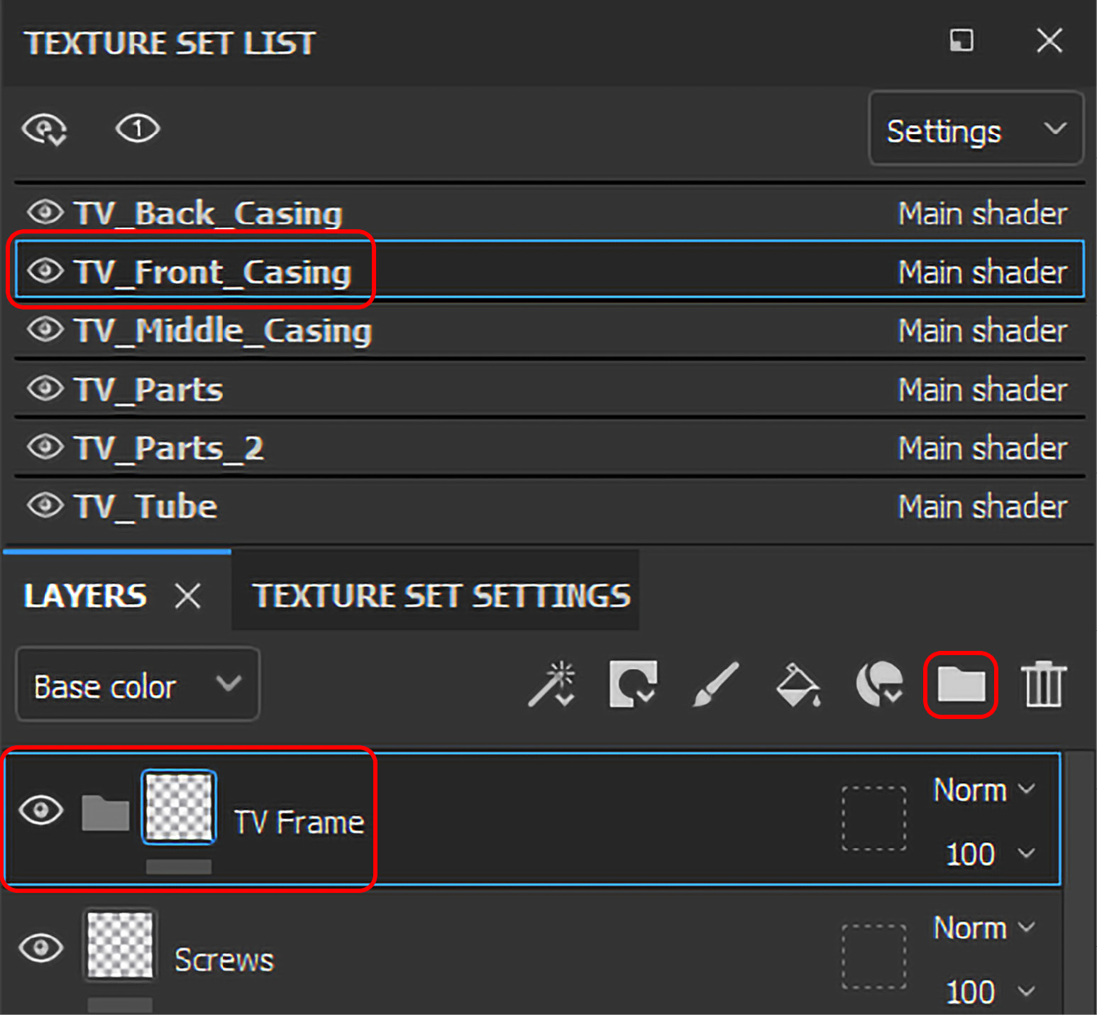
Figure 6.2 – Creating a new folder in the TV_Front_Casing Texture Set
- Now, we have to create a TV Frame base material. Firstly, click on Add fill layer to create a new fill layer inside the TV Frame folder. Secondly, rename the fill layer Frame Base Material, and lastly, change Base color to 979268 and Roughness to 0.27.

Figure 6.3 – Creating a frame base material
- Now, create another fill layer, rename it Frame Dirt Material, and change Base color to 382F0E and Roughness to 0.18.
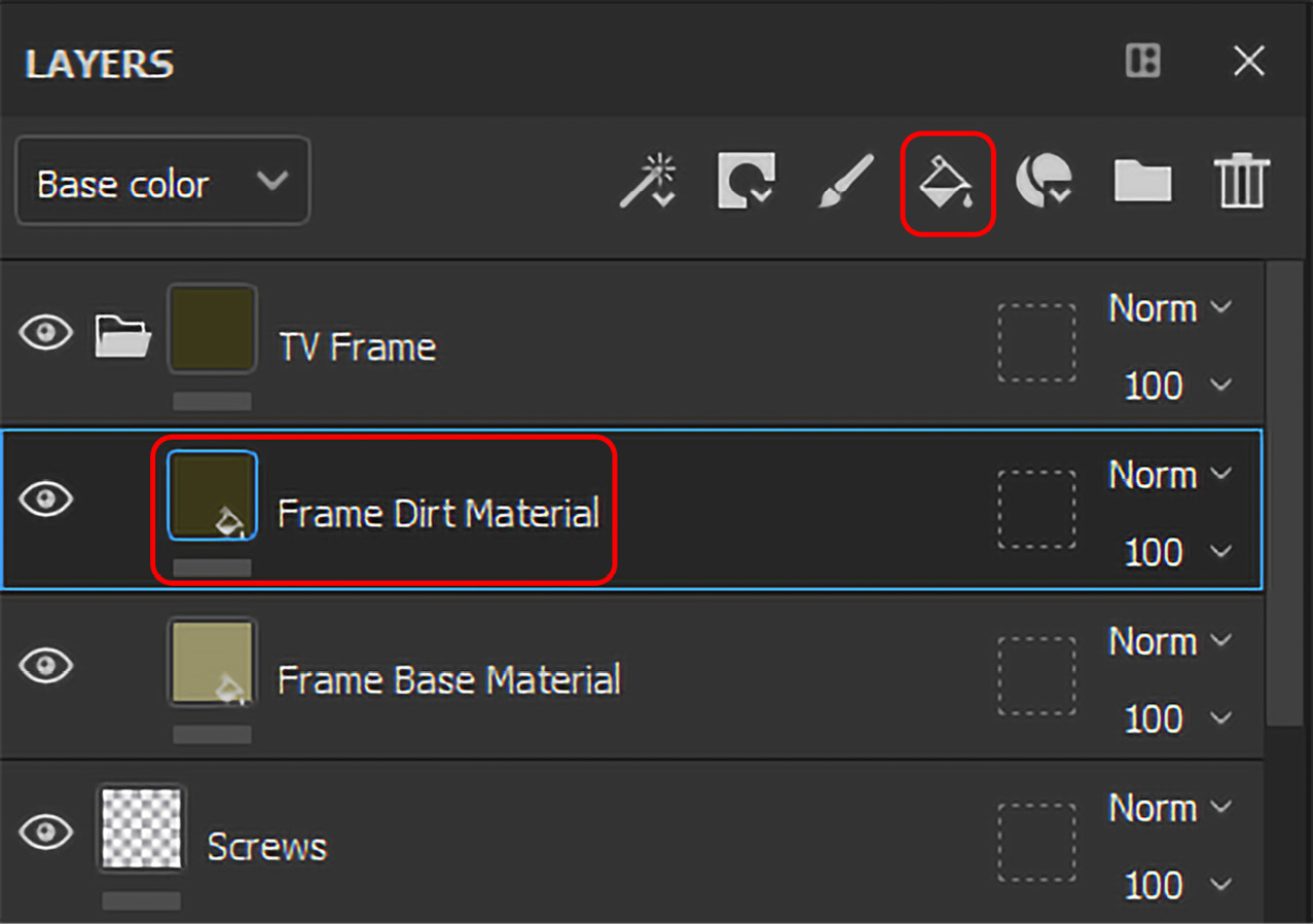
Figure 6.4 – Creating the Frame Dirt Material fill layer
- It’s time to add a black mask to Frame Dirt Material so that when we add the masking effect, the effect appears in the white area only. Therefore, go to Add mask, click on it, and choose to Add black mask.

Figure 6.5 – Adding a black mask to Frame Dirt Material
- Let’s add some edge wear effect to the frame to make it look like old material with wear and tear. So, go to Add effect, click on it, and then select Add generator. Once the generator is added, go to PROPERTIES - GENERATOR, click on the Generator option, and then select the Metal Edge Wear generator.
Figure 6.6 – Adding the Metal Edge Wear generator
- Once the Metal Edge Wear generator is added, you need to change its parameters to make it look more realistic. Change the following settings:
- Wear Level: 0.9
- Wear Contrast: 0.33
- Grunge Amount: 0.42
- Curvature Weight: 0.35
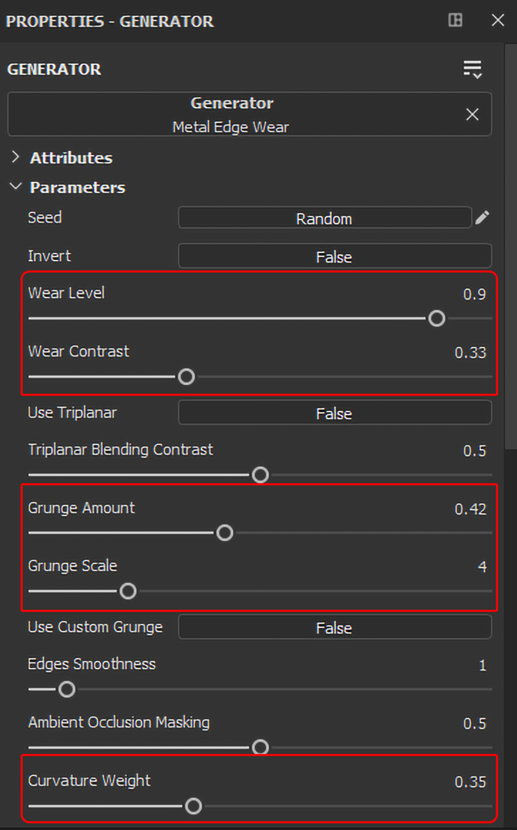
Figure 6.7 – Changing the generator’s parameters
- Now, collapse the TV Frame folder so that everything inside the LAYERS panel looks neat and organized.

Figure 6.8 – Collapse all folders
- Now, we will convert this TV Frame material to a Smart Material. Right-click on the TV Frame layer and select Create Smart Material.

Figure 6.9 – Creating a Smart Material
- Once you click on Create Smart Material, the TV Frame material will become a Smart Material and will be shown in the Smart Material asset type. This material can be applied at any time in any project to any 3D model by adjusting its settings and parameters.

Figure 6.10 – TV Frame Becomes a Smart Material
- However, the TV Frame material is all over TV_Front_Casing, and we need it only on TV Frame. Therefore, keep the TV Frame folder selected, choose Add mask, and select Add mask with color selection. Then, select Pick color under COLOR – SELECTION and click on TV Frame, as shown in Figure 6.11.

Figure 6.11 – Apply the TV Frame Smart Material to the frame only
- Now, as the TV Frame Smart Material is masked to frame itself, the result will look more realistic, as shown in Figure 6.12.
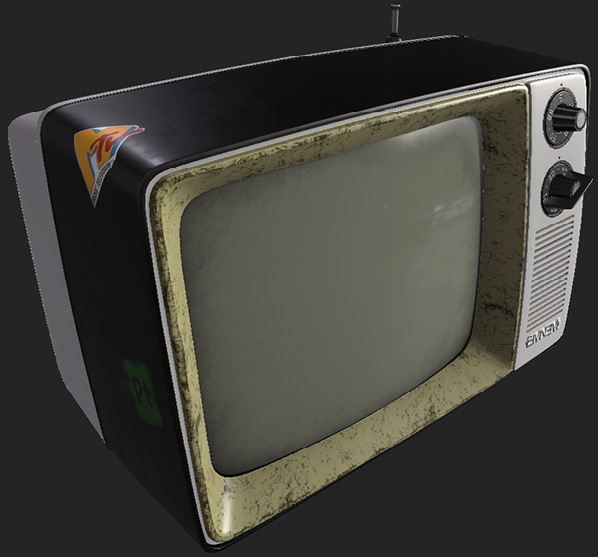
Figure 6.12 – Final output of the TV Frame Smart Material
Now that you know how to create your own Smart Material from scratch, in the next section, we will learn how to create our own Material or Smart Material from existing materials.
Creating a material or Smart Material from an existing material in Adobe Substance 3D Painter
Sometimes, it is easier and faster to create a Material or Smart Material from an existing Smart Material or material. In this section, we will create a dark plastic material and apply it to everything with a maroon ID map.
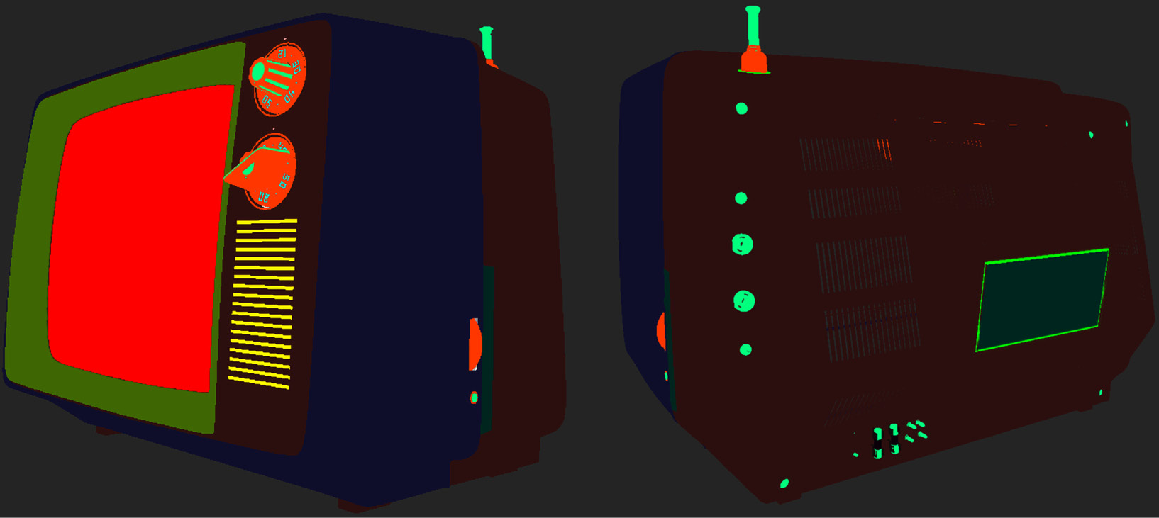
Figure 6.13 – A maroon ID map
- Select TV_Front_Casing from TEXTURE SET LIST, click on Add group, and rename it Dark Plastic Parts. Then, inside the folder, create a new fill layer by clicking Add fill layer, and rename it Plastic Material. Make sure the new folder is under the TV Logo layer so that it doesn’t hide the logo layer and the layers above it.
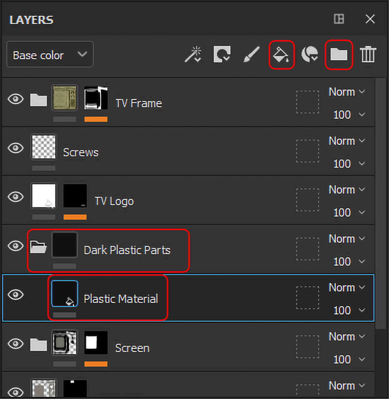
Figure 6.14 – Creating a new fill layer
- Make sure that the Plastic Material layer is selected, go to the ASSETS panel, choose the Material asset type, and select Plastic Matte Pure.

Figure 6.15 – Selecting the Plastic Matte Pure material
- Now, go to the PROPERTIES - FILL window of the Plastic Material fill layer and change the following settings under the MATERIAL settings.
- Base color: 111111
- Roughness: 0.17
- Metallic: 0

Figure 6.16 – Adjusting the Dark Plastic Parts layer material

Figure 6.17 – Creating the Dark Plastic Parts Smart Material
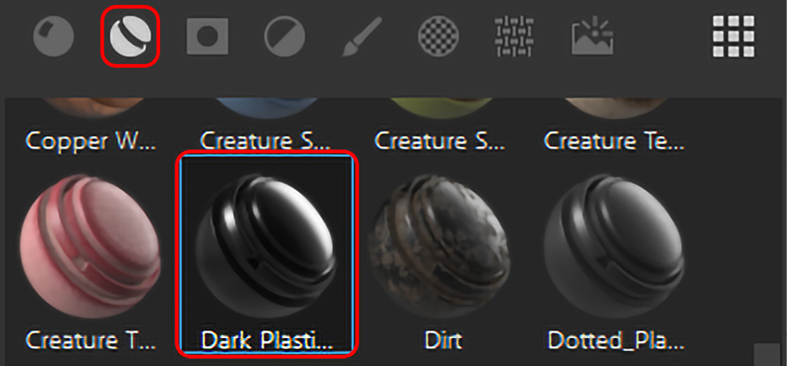
Figure 6.18 – The Dark Plastic Parts Smart Material
- Now, we want the Dark Plastic Parts Smart Material only on the front part of the TV and not on the screen. Therefore, select the Dark Plastic Parts folder, click on Add mask, and choose Add mask with color selection.

Figure 6.19 – Creating a mask with color selection on the Dark Plastic Parts layer
- Now, go to the PROPERTIES - COLOR SELECTION, select Pick color under the COLOR SELECTION settings, and click on the front part of the TV, as shown in Figure 6.20.
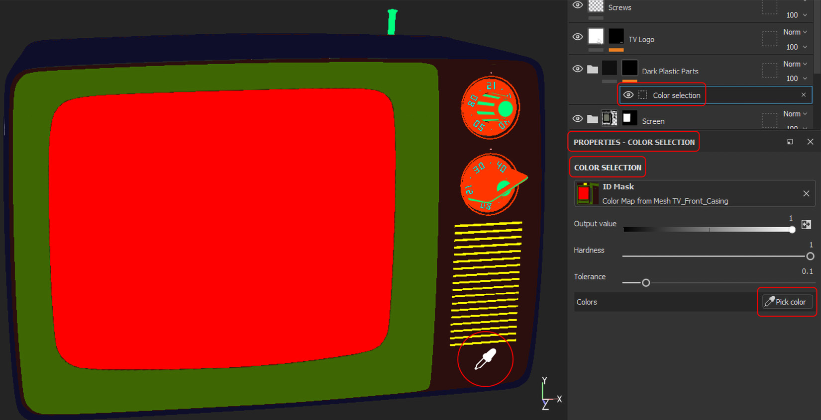
Figure 6.20 – Applying the Dark Plastic Parts material on the front part
- Now, go to the TV_Back_Casing, TV_Parts, and TV_Parts_2 Texture Sets and apply the Dark Plastic Parts Smart Material to all the parts with the maroon ID maps in each Texture Set, as shown in Figure 6.13, with ID map material applying the technique. To make it clearer, this is done by dragging and dropping in the material and adding a mask with color selection. The final output will look the same as Figure 6.21.

Figure 6.21 – The Dark Plastic Parts final output
Hopefully, it has been clear to all of you how we can create Materials or Smart Materials from scratch or any existing Materials or Smart Materials. In the next section, we will add Materials to the rest of the parts, and we will have some fun while applying stickers and decals to the TV.
Applying stickers and decals in Adobe Substance 3D Painter
We have added a lot of Materials and Smart Materials in our previous lessons, and we have added some stickers too. In this section, we will apply Materials to the rest of the TV parts and also apply stickers and decals using different techniques:
- First, let’s complete applying materials to the TV_Back_Casing Texture Set. Go to the ASSETS panel and search Plastic Grainy, and then apply this material to the frame of the TV_Back_Casing servlet area while pressing Ctrl (Windows) or Cmd (Mac) on your keyboard. Once the servlet’s frame shows a light green ID map, drop the material onto it, as shown in Figure 6.22.

Figure 6.22 – Applying Plastic Grainy to TV_Back_Casing’s servlet frame
- Now, we will apply materials to the TV_Parts Texture Set. Go to ASSETS and use the same Plastic Grainy material used in step 1, and then apply this material to the knob numbers while pressing Ctrl (Windows) or Cmd (Mac) on your keyboard. Once the knob numbers will show a light blue ID map, drop the material onto it, as shown in Figure 6.23.
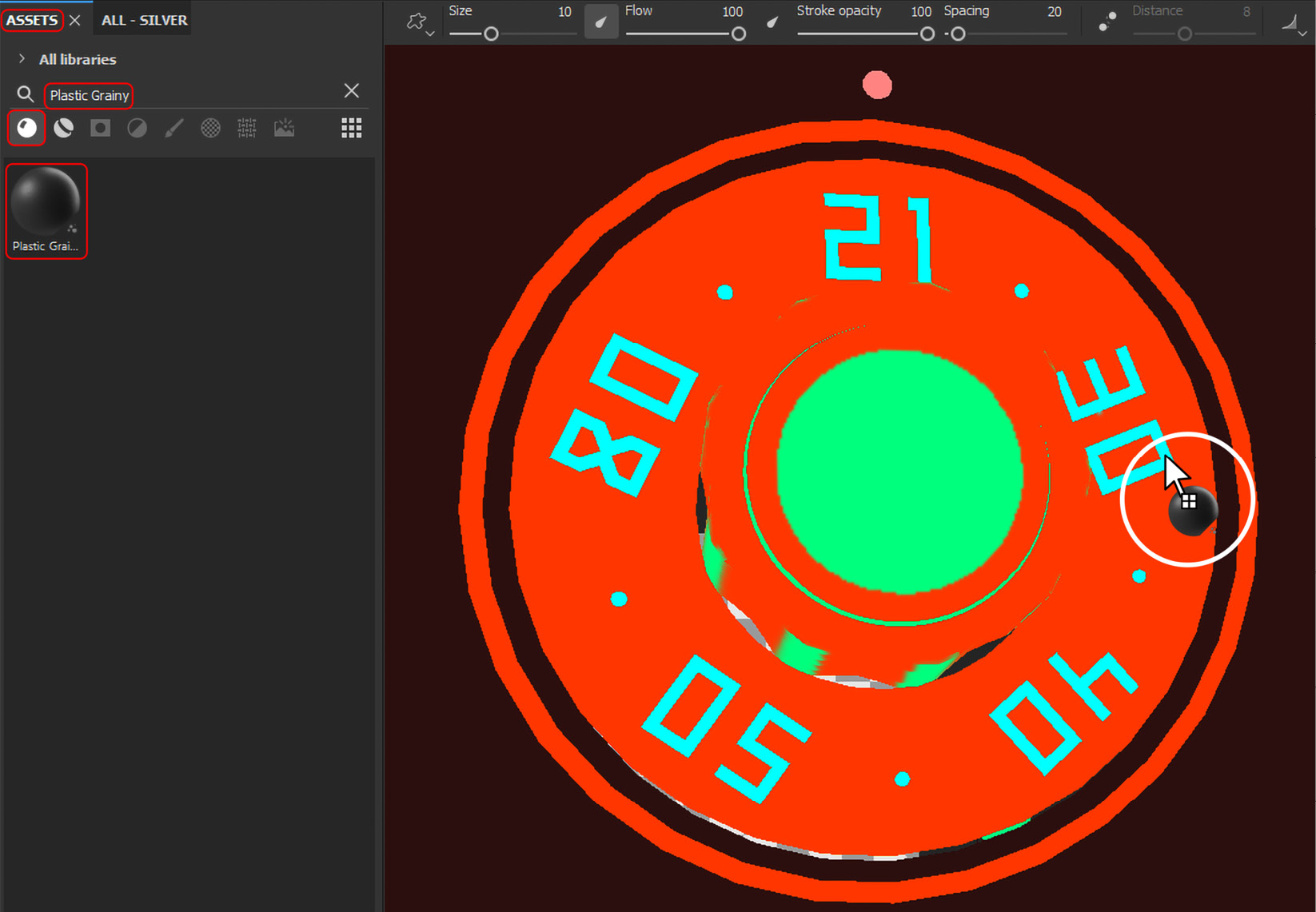
Figure 6.23 – Applying material to knob numbers in the TV_Parts Texture Set
- Now, let’s go to the back side of the TV_Parts Texture Set and search for the TV fuse, which is located at the bottom of the back side of the TV. This is the place we will be applying materials. Go to ASSETS and search for the Plastic Dirty Scratched material, and then apply this material to the TV fuse while pressing Ctrl (Windows) or Cmd (Mac) on your keyboard. Once the TV fuse shows a dark green ID Map, drop the material onto it, as shown in Figure 6.24.
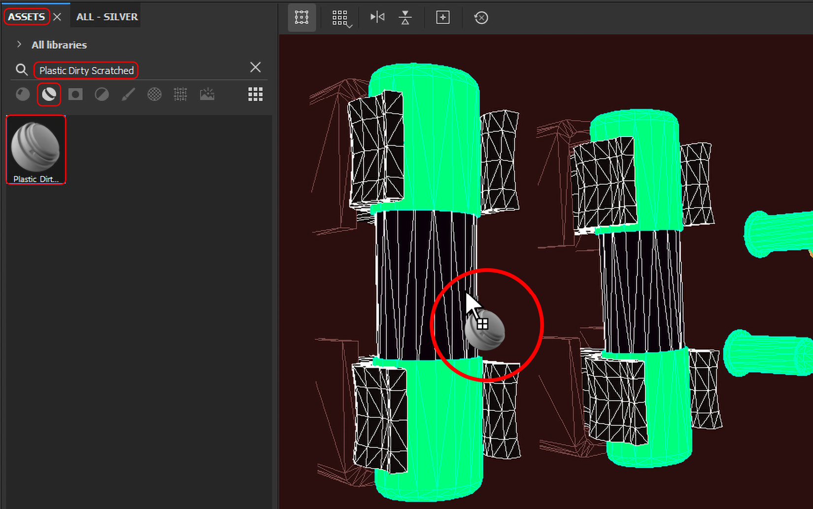
Figure 6.24 – Applying Plastic Dirty Scratched to the TV fuse in the TV_Parts Texture Set
Now that we are done with applying materials to all latent 3D parts, let’s now start applying stickers.
- First, go to the ASSETS panel, select the Brushes asset type, and choose the Basic Hard brush. Then, go to All libraries under the ASSETS panel and choose the Project library. Then, click on the small arrow next to the Project library and select Retro. You will see all the stickers that you need to apply.
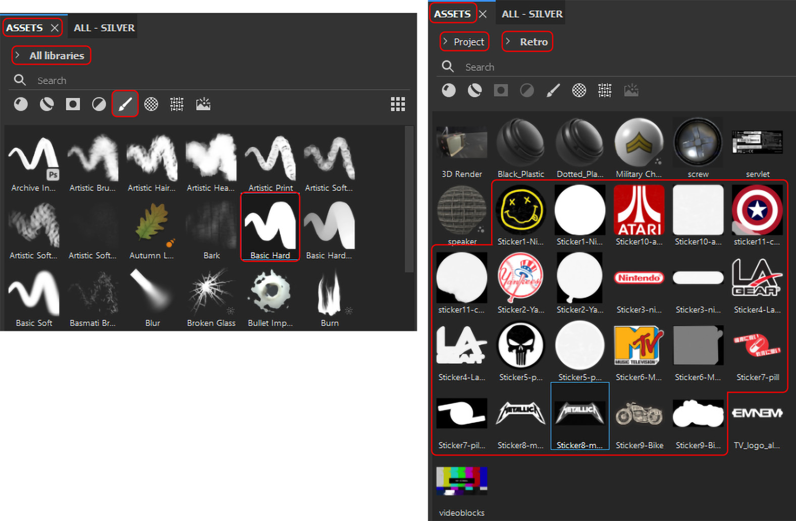
Figure 6.25 – Selecting stickers
- Let’s create a new paintable layer so that we can apply stickers to it. Click on Add layer in the LAYERS panel to create a new paintable layer, rename it Stickers, and keep it selected.
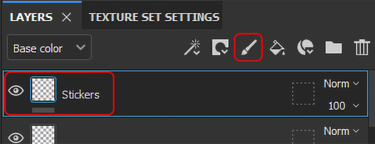
Figure 6.26 – Creating a new paintable Stickers layer
- Now, let’s create a sticker brush so that we can apply stickers to the TV_Middle_Casing Texture Set. Go to PROPERTIES - PAINT and choose the sticker you want to apply. Drag the base color of that sticker to Base color in PROPERTIES - PAINT, and the alpha of the sticker to Alpha in PROPERTIES - PAINT, as shown in Figure 6.27. If you do not want to drag images, you can also click on the Base color and Alpha, and then choose your desired images from the list.
- For stickers, we need to activate only color, height, rough, and metal. Keep Height at 0.02; this will give depth to the sticker so that it will have a realistic thickness. Change Roughness and Metallic to your desired settings; Roughness will give you a shine and Metallic will give you reflection. I have chosen Roughness as 0.1497 and Metallic as 0.1463.

Figure 6.27 – Creating a sticker brush
- Now, decide on a location in the TV_Middle_Casing Texture Set to apply your sticker to. You can rescale the sticker brush size by pressing the Ctrl (Windows) key or the Cmd (Mac) key on your keyboard and dragging the mouse left or right with the right mouse button pressed.
To change the direction/rotation of your sticker brush, keep the Ctrl (Windows) key or Cmd (Mac) key on your keyboard pressed and drag the mouse up or down with the mouse left button pressed.
To change the flow of your sticker brush, keep the Ctrl (Windows) key or Cmd (Mac) key on your keyboard pressed and drag the mouse left or right with the mouse left button pressed. You can change these settings using the contextual toolbar, as shown in Figure 6.28.

Figure 6.28 – Settings to adjust the brush
- To apply new stickers, you need to remove the existing Base color and Alpha settings by pressing the cross next to them and repeating step 6. We can also repeat step 6 without deleting the existing Base color and Alpha settings. Keep applying the stickers of your choice. However, do not apply a lot of stickers; otherwise, the design will look unprofessional. The final output should look something like Figure 6.29.
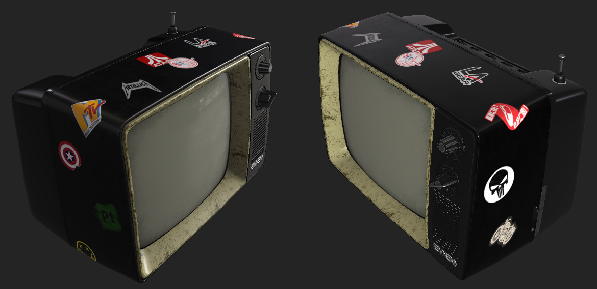
Figure 6.29 – The final output of the sticker application
Now that we have applied the stickers on the TV, in the next section, we will learn to apply an overall effect that will make the 3D model more look like a one-piece model.
Adding an overall layer effect with the position map in Adobe Substance 3D Painter
Whenever you want to strengthen or double any effect or apply an effect to a whole 3D model as a one-piece model, we have effects such as Position and Add anchor point. So, let’s learn these effects in detail in two separate sections.
Adding an anchor point
Anchor points are used to expose any resource or element and reference it in various parts of the Layer Stack, for various reasons and with various changes.
They bring up a whole new world of possibilities by letting you link layers or masks together. Having a single anchor point influences several areas of your project, thereby turning Substance 3D Painter into a non-linear experience.
Let’s double the effect of the TV Logo layer inside the TV_Front_Casing Texture Set:
- Go to the TV_Front_Casing Texture Set, and then select the TV Logo layer mask in the LAYERS panel. Then, go to Add effect and select Add filter to add a filter over the Fill layer. Keep the Filter (empty) layer selected, go to PROPERTIES - FILTER, click on the Filter area under FILTER settings, and choose the Blur filter, as shown in Figure 6.30.

Figure 6.30 – Adding the Blur filter to the TV Logo layer mask
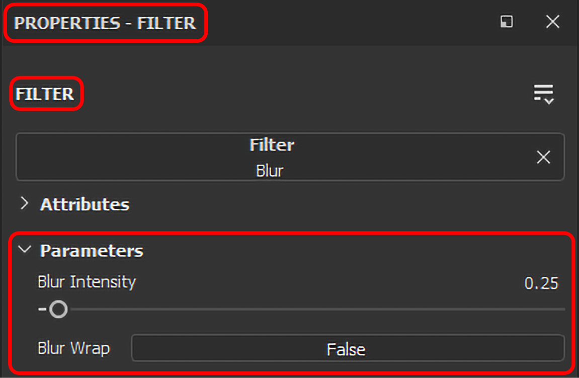
Figure 6.31 – Changing the blur settings
- Now, select the newly added Levels layer, which is added by clicking on the add effect button. Then, go to its PROPERTIES - LEVELS, and change Input gamma to 3 and Input maximum to 0.8 under the LEVELS settings by double-clicking on the number above the arrows, as shown in Figure 6.32.

Figure 6.32 – Adjusting the TV Logo levels
- Now, it’s time to add an anchor; therefore, keep the Levels layer selected, then click on Add effect, and select Add anchor point. Once the anchor is created, rename it TV Logo mask.
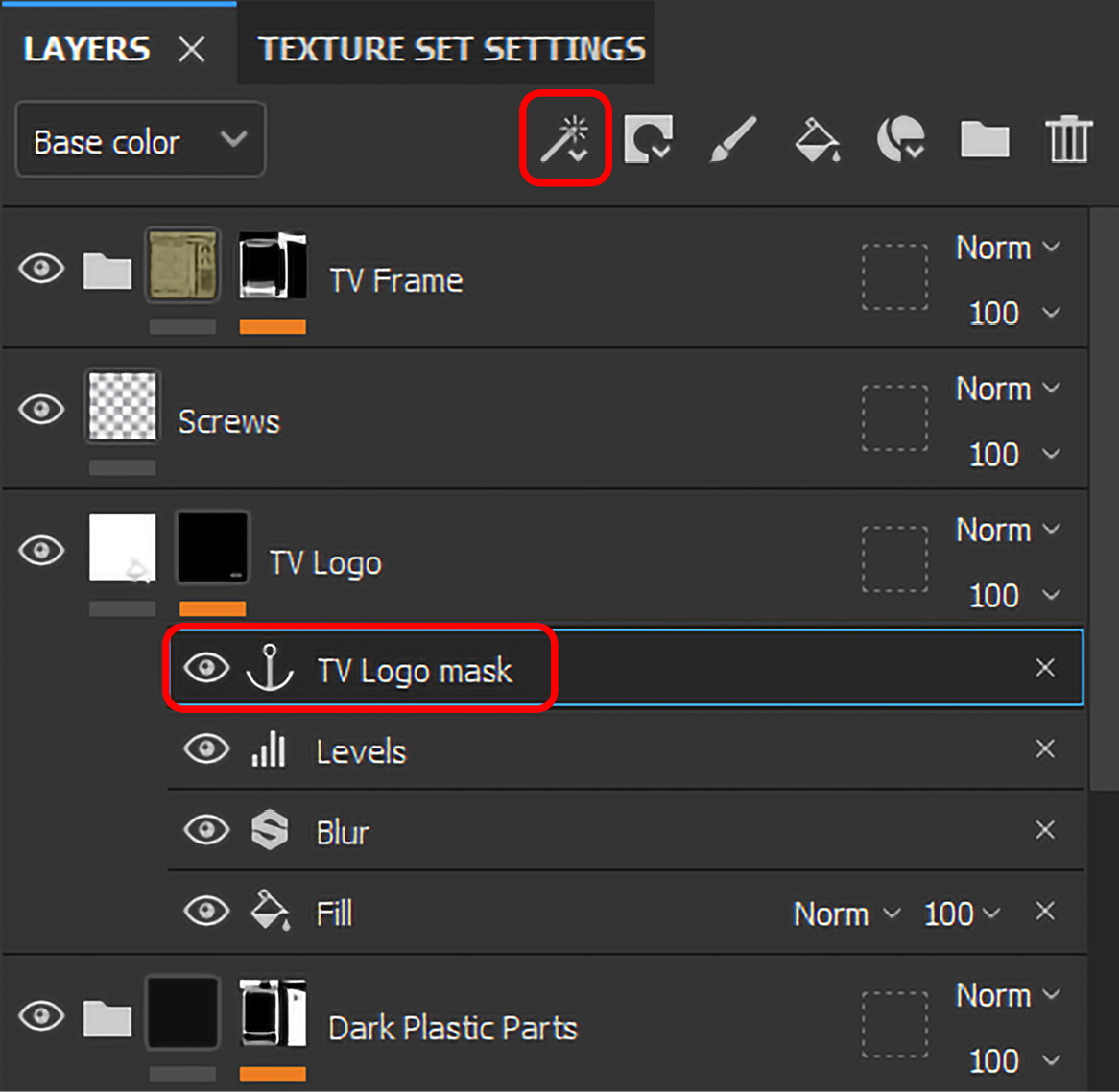
Figure 6.33 – Adding an anchor point
- We are done with all the effects we need. Now, to double these effects, we have to create another Fill layer over TV Logo and rename it TV Logo Double Effects. Then, inside PROPERTIES - FILL, uncheck all the MATERIAL settings except height, and change the Height value to 1, as shown in Figure 6.34.
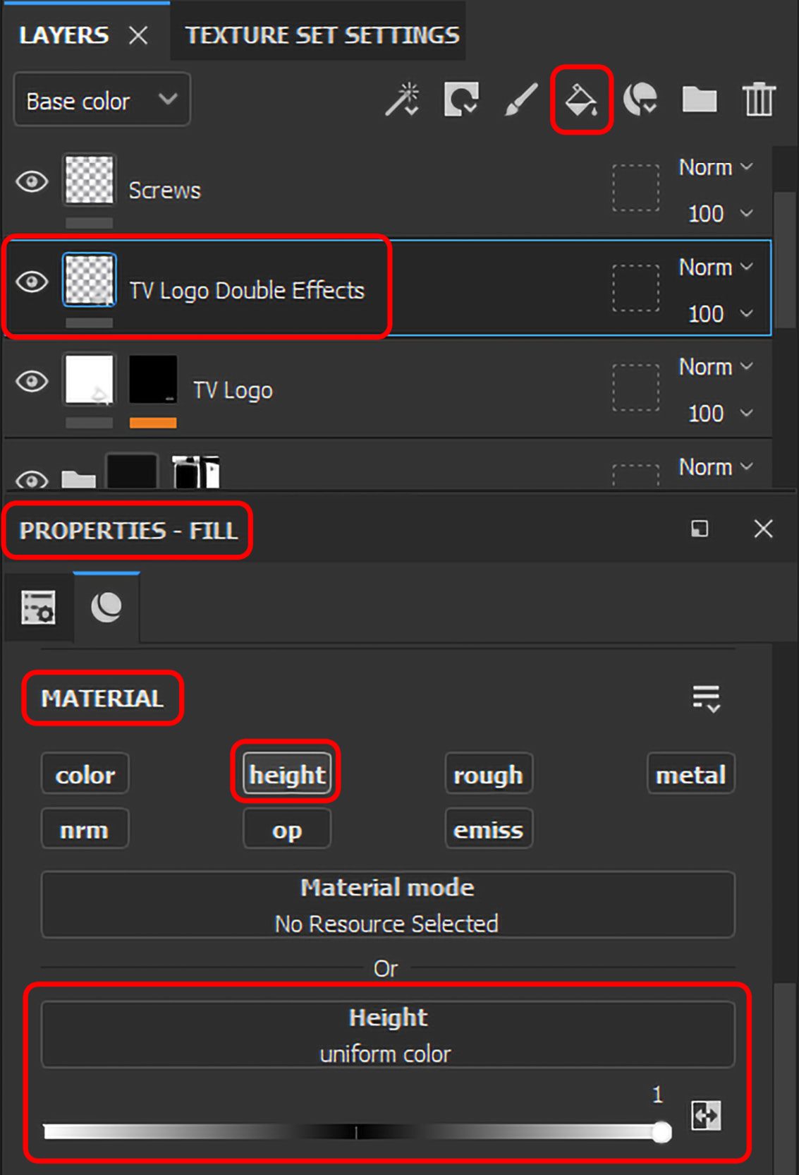
Figure 6.34 – Adding a new TV Logo Double Effects fill Layer
- Now, add a black mask from the Add mask option, then add a new fill layer to that mask from the Add effect option, and rename it TV Logo Double Effect Fill, as shown in Figure 6.35.
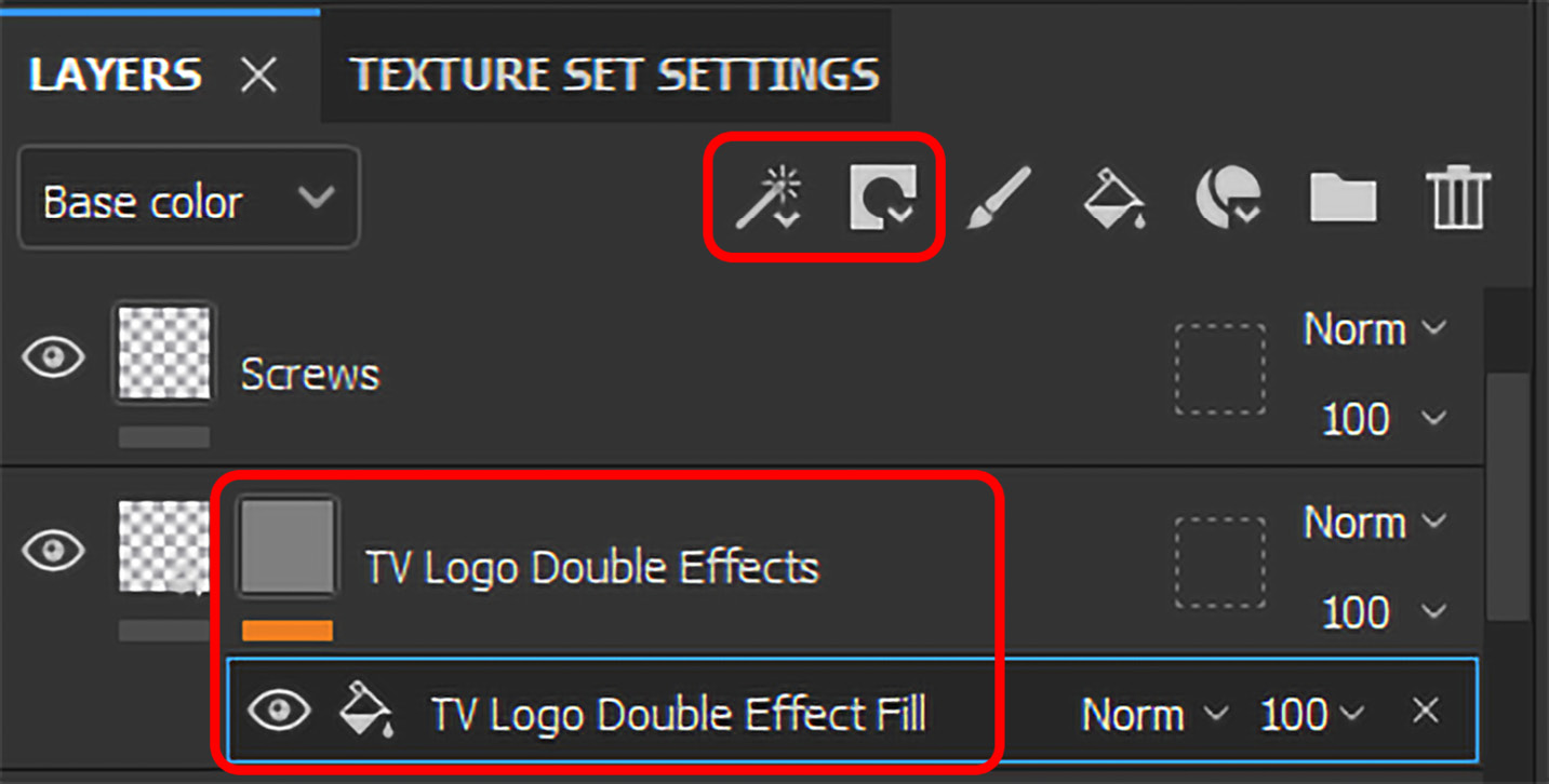
Figure 6.35 – Adding a black mask and Fill layer to the TV Logo Double Effects layer
- Keep the TV Logo Double Effect Fill mask fill layer selected and go to its PROPERTIES - FILL window. Under the GRAYSCALE settings, click on the grayscale option. As soon you will click on it, you will see the RESOURCES and ANCHOR POINTS tabs; select the ANCHOR POINTS tab. Under that tab, you will find the anchor you previously created; click that TV Logo mask anchor.

Figure 6.36 – Choosing ANCHOR POINTS
- Once you will do that, you will notice that the height, blur, and level effects have been doubled. This is how ANCHOR POINTS helps you to repeat the effect. Because it is an instance, you can change the original effect settings. Also, wherever these effects are anchored, they will change automatically, as shown in Figure 6.37.

Figure 6.37 – The TV Logo Repeated Effects final output
Now that you know the technique to double or repeat any effect, we will move to apply an effect called Position using the Add generator and Add effect options in the next part of this section.
Using Position maps to add an overall dust effect on multi-Texture Set 3D models and 3D meshes
The Position map creates a texture with the coordinates of each point on the 3D mesh. To put it another way, this tells Painter where the mesh’s top, bottom, front, rear, and left and right sides are. It helps a user to count a 3D model with multiple Texture Sets as a one-piece model.
To work on the Position map, you need to make sure you activate it with Normalization Scale set to Full Scene while baking the textures, as shown in Figure 6.38, which we did in Chapter 1, Getting Started with Adobe Substance 3D Painter.
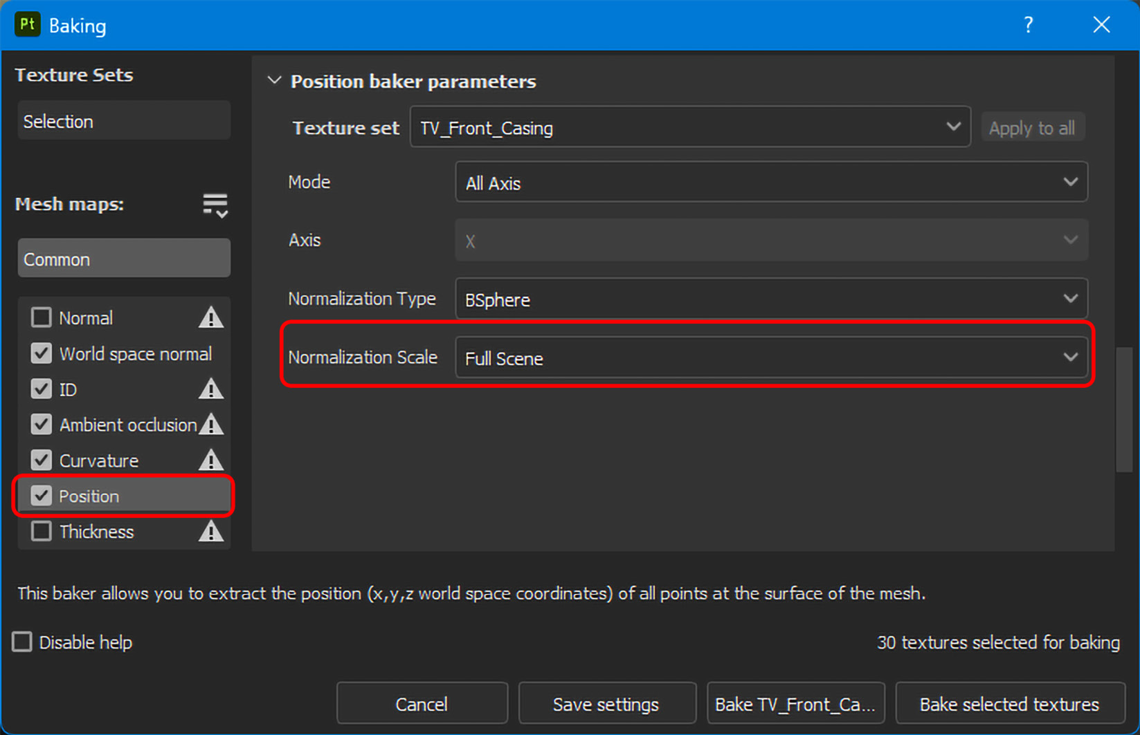
Figure 6.38 – Activating the Position map for baking with a Full Scene normalization scale
- To add a Position map, you can choose any Texture Set; in this project, I’m choosing the TV_Middle_Casing Texture Set. Then, create a new fill layer with the help of the Add fill layer option and rename the new layer Dust Effect. Under PROPERTIES - FILL, deselect all the MATERIAL settings except color, height, and, rough. Now, change Base color to C2B280, Height to 0.02, and Roughness to 1.

Figure 6.39 – Creating a new Dust Effect fill layer
- Now, add a black mask to the Dust Effect fill layer from the Add mask option, and then add a generator to the black mask from the Add effect option. Then, select Generator (empty), go to PROPERTIES - GENERATOR, and under the GENERATOR settings, click on the Generator area and choose Position.

Figure 6.40 – Adding the Position map by adding the Generator effect
Now, the TV with the Position map effect will look like Figure 6.41.

Figure 6.41 – The Position map effect on TV_Middle_Casing
- To see the gradient map of the Position map effect, press Alt (Windows) or Option (Mac) on your keyboard and click on Dust Mask, as shown in Figure 6.42.
The black and white gradient mask will help you identify where the strength of the mask is and where the weakness is. The texture or material will appear with full visibility in the stronger area, which is whiter, and less visible in the weaker area, which is dark. Once you get the idea of the gradient, disable it by simply clicking on the main Dust Effect layer.

Figure 6.42 – Enabling the gradient map of the Position map effect
- First, make sure you are still inside the Dust Effect mask, then add a new fill layer above the Position map effect from the Add effect option, rename the new fill layer Grunge Dust Spread, keep it selected, and go to PROPERTIES - FILL. Under the GRAYSCALE setting, click on the grayscale area and search for the Grunge Dust Spread or Grunge Dust Small map, and then select it once it appears.

Figure 6.43 – Creating a new fill layer in Dust Effect Mask
- Now, it’s time to apply this effect to all the other Texture Sets. To do that, right-click on the main Dust Effect layer and choose Instantiate across texture sets.

Figure 6.44 – Instantiating Dust Effect on all Texture Sets
- Once you click the Instantiate across texture sets option, the Instantiate across Texture Sets window will pop up. Make sure that all the Texture Sets are selected, except for the source Texture Set, which is TV_Middle_Casing in our case, and then click OK.

Figure 6.45 – Selecting Texture Sets for instantiation

Figure 6.46 – The dust effect on the whole 3D model
- To make the dust effect more realistic, click the black mask of the Dust Effect layer and select the Grunge Dust Spread fill layer inside the Dust Effect layer mask. Then, go to its PROPERTIES - FILL window and change the following settings:
- Projection: Tri-planar projection
- UV transformations | Scale: 2.4
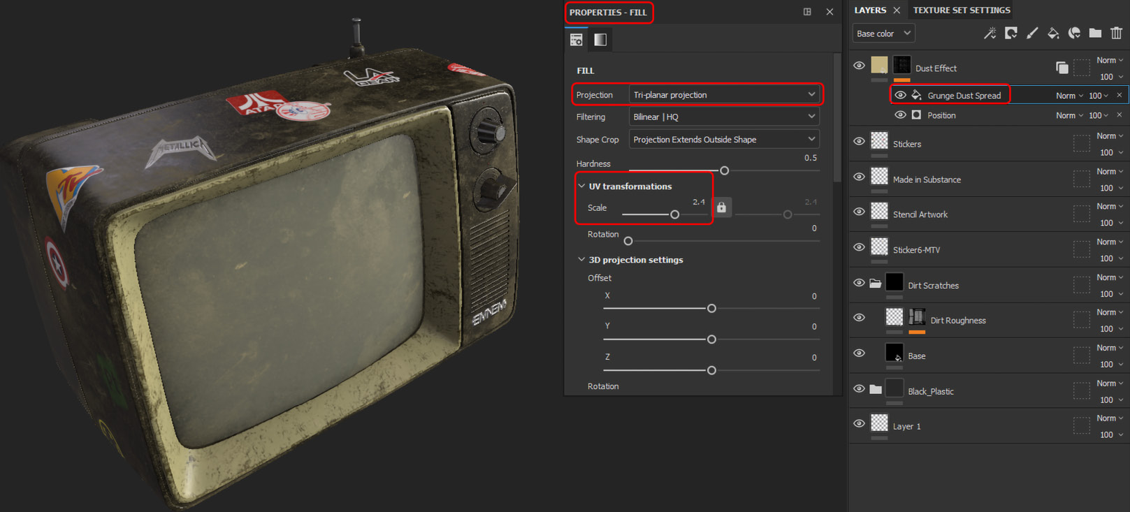
Figure 6.47 – Adjusting the Grunge Dust Spread fill layer
- The TV model and the texturing are now almost ready, except for the dust effects strength. You will notice that the dust effect is too strong; therefore, you can select the main Dust Effect layer and reduce its opacity to around 50, as shown in Figure 6.48.

Figure 6.48 – Adjusting Dust Effect’s opacity
Hopefully, you now know how to use anchor points and Position maps, which will help you to repeat an effect and apply it to a whole 3D model respectively. Now, as we have completed texturing and painting our 3D model using Adobe Substance 3D Painter, in the next section, we will learn how we can export these textures.
Exporting textures from Adobe Substance 3D Painter
Exporting textures from Painter is the last process when you want to export your completed textures to third-party 3D applications such as Autodesk 3D Studio Max, Maya, or Blender.
So, let’s begin exporting them:
- First, go to the File menu and click on it; then, choose the Export Textures option.

Figure 6.49 – The Exporting Textures option
- When the Export textures window pops up, you need to first adjust SETTINGS. Global settings change the General Export Parameters of all Texture Sets; however, you can select any specific Texture Set under Global settings and change General Export Parameters.
- Under General Export Parameters, you can decide where you want to save your texture from the Output directory option. You can also select your Output template option – for example, if you are working in Unreal Engine, you can choose Unreal Engine, or if you are working in V-Ray, you can choose Vray.
- For this project, we will choose Substance 3D Stager. For the Substance 3D Stager template, File type is disabled; however, you can choose different types, such as PNG or JPEG, if you are working on a different output template.
- You can choose your desired size from the Size option; we will choose 4096 to export 4K-quality textures. The last option is Padding, which allows you to adjust the border of your textures; the best setting is Dilation infinite, because it keeps your texture borders within your UV tiles to avoid showing any visible gaps and borders.
- Finally, you can also enable Export shaders parameters if you want the 3D application, where you are exporting your textures, to adjust its parameters.

Figure 6.50 – Export textures | SETTINGS
- Usually, we do not change the settings of any Texture Set and their channels separately. However, if you want to, you can select the desired Texture Set, click on the Edit button, as highlighted in Figure 6.51, and edit the settings.

Figure 6.51 – Editing individual Texture Set general export parameters and output maps
- When you click on the Edit button, you will notice that you can change the bits of the roughness texture channel, as shown in Figure 6.52; however, you cannot change file types for some output template channels. To do that, you can revisit step 7.
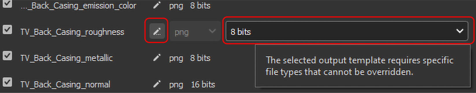
Figure 6.52 – Editing a specific Texture Set
- When you are unable to change the file type of any specific texture channel or you want to keep a specific texture channel’s file type different from other channels, you can go to the OUTPUT TEMPLATES tab of the Export textures window, select the output template preset, and change the file type or bits of the channel you want.
The other maps in this tab are just to show information. However, we are not going to change anything; this step is only for educational purposes.

Figure 6.53 – The OUTPUT TEMPLATES settings
- The last tab in Export textures is LIST OF EXPORTS, which shows you a list of Texture Sets and their channels that are going to be exported. You need to just click on the Export option. It also shows the list of Texture Sets and their channels when they are successfully exported in a teal or turquoise color
- To see your exported textures, click on Open output directory in the top-right corner of this tab.

Figure 6.54 – Exporting and opening the export folder from the LIST OF EXPORTS tab
- Once you click on Open output directory, the folder where you exported your textures will open. Now, you can use your desired third-party 3D application and start applying these textures. In our case, we have used Substance 3D Stager as our output template, so we will be using these textures again in the Adobe Substance 3D Sampler part of this book.

Figure 6.55 – The exported output directory
Now that you have learned one of the most crucial skills of Adobe Substance 3D Painter, which is to export final textures and use them in your desired 3D application, it’s finally time to end the Adobe Substance 3D Painter part of this book by learning how to render using Adobe Substance 3D Painter’s Iray renderer in the next section.
Rendering in Adobe Substance 3D Painter using Iray
After completing a project, users always want to visualize how a model will look in reality; therefore, in this section, you will learn how to render an Adobe Substance 3D designer project:
- First, you need to go the Mode menu and choose Rendering (Iray).

Figure 6.56 – Rendering (Iray) mode
- Once you select Rendering (Iray), the 3D viewport will switch to rendering mode after a little warm-up. The Iray rendering mode uses real-time rendering, which means you can navigate the viewport and it will keep on rendering every time you adjust it.

Figure 6.57 – Iray’s real-time rendering viewport
- Note that the TV 3D model is flying in the air, so let’s shift the ground up so the TV sits on it, unless you want it to fly in the air on purpose. Go to Display Settings and jump to the Ground settings. Make sure you tick the Ground checkbox to make the ground ivisible, and change its Y-axis setting to -3.65.
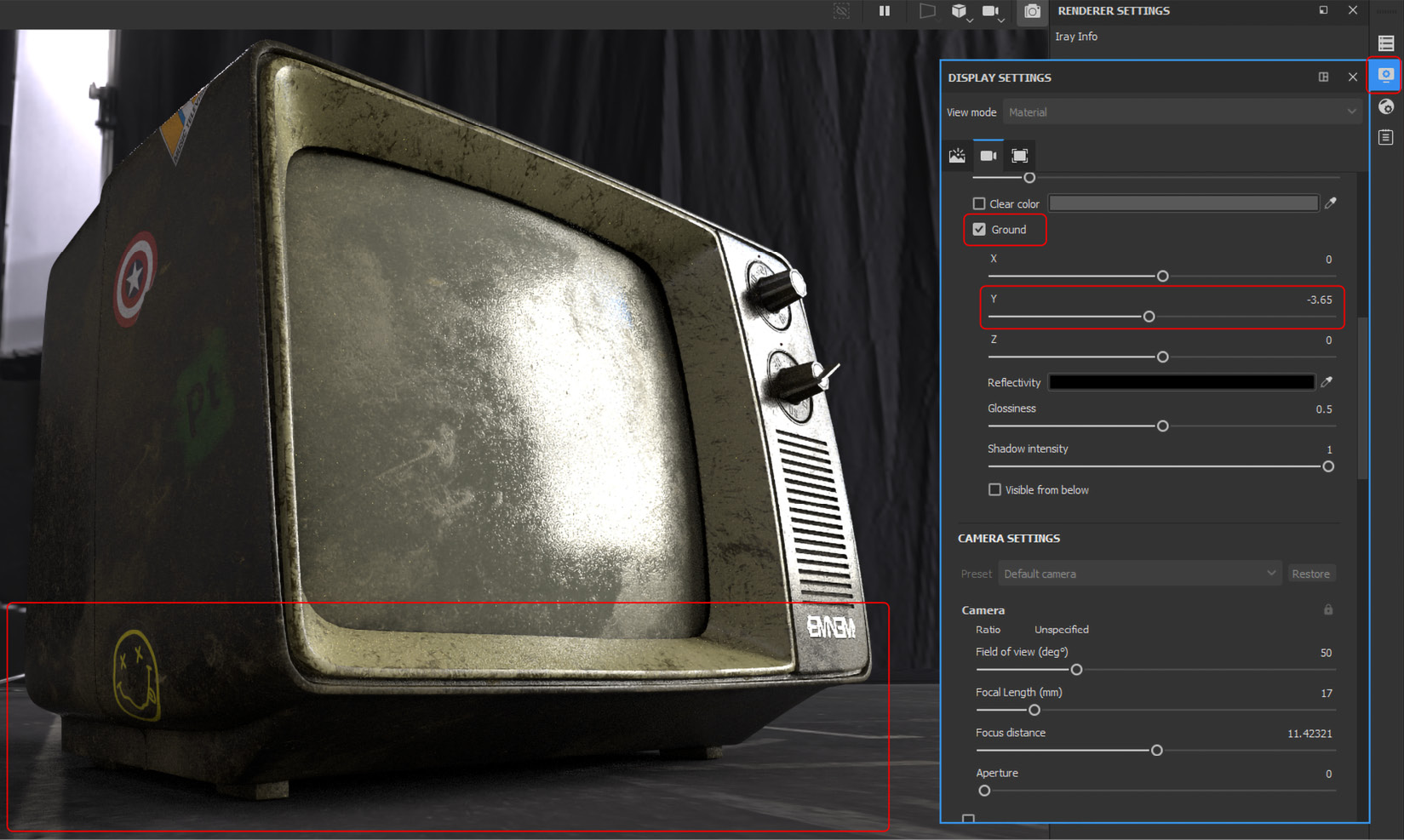
Figure 6.58 – Changing the Ground settings
- You can also change the light settings by rotating the environment. Either go to ENVIRONMENT | SETTINGS and adjust Environment Rotation, or do the same by dragging the mouse with the middle mouse button pressed across the viewport, while keeping the Shift key on the keyboard pressed. Moreover, in the latest versions, it can be done by holding Shift and pressing the right mouse button.
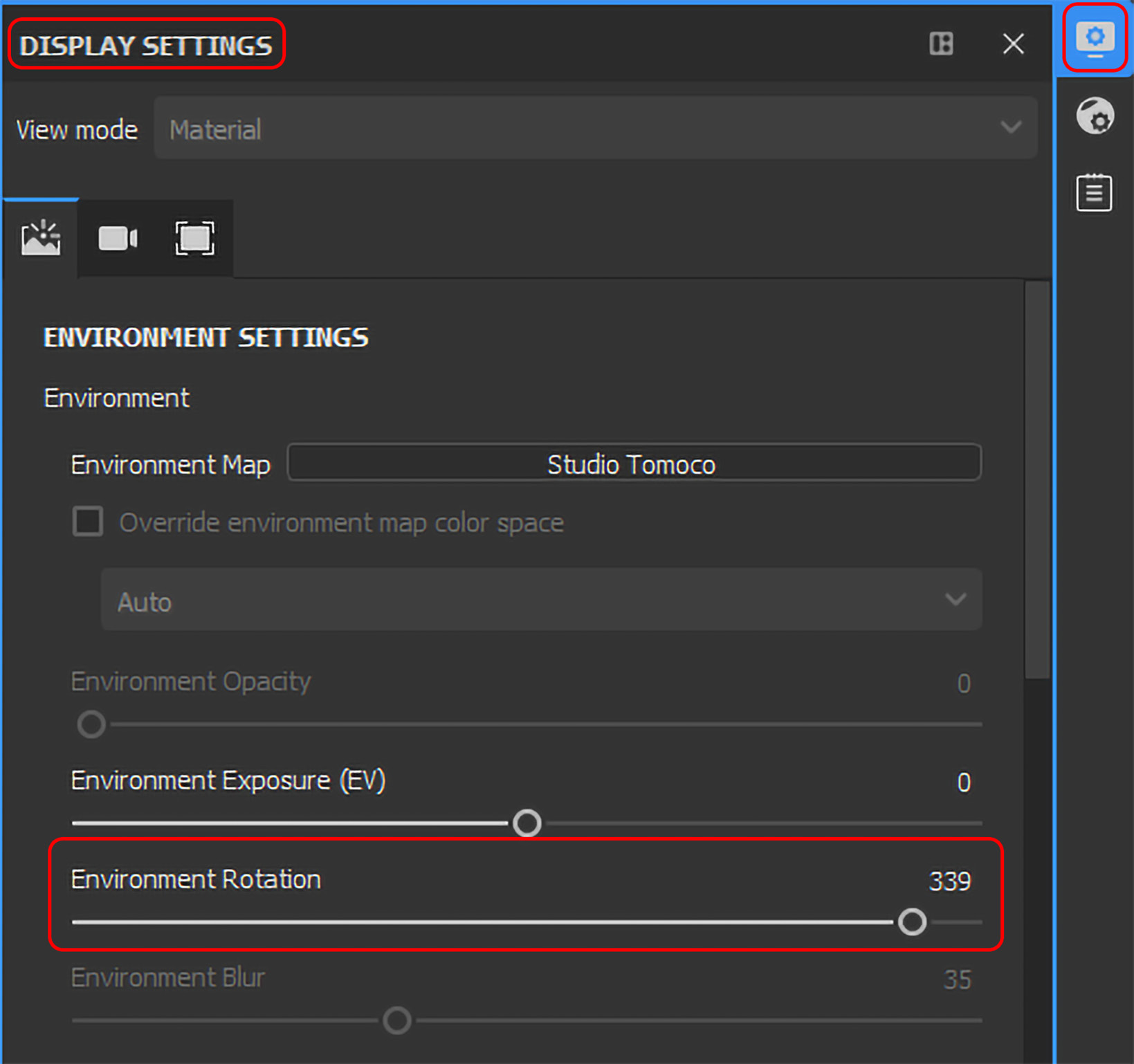
Figure 6.59 – Rotating the environment to change the light settings
- In DISPLAY SETTINGS, you can also change the Camera settings and Activate Post Effects, so let’s try a few effects.
- First, we will try the DOF (Depth of Field) effect. For DOF, the camera Aperture size should be higher; therefore, change it to 0.5. Then, click on the Activate Post Effects and DOF checkboxes, as shown in Figure 6.60. Now, we need a focal point; you can adjust this by changing the Focus distance option. You can also press on the 3D model area that you want to focus on with the middle mouse button while keeping the Ctrl (Windows) or Cmd (Mac) key pressed on your keyboard. Note now that the TV’s back part is blurred while the front part is in deep focus.
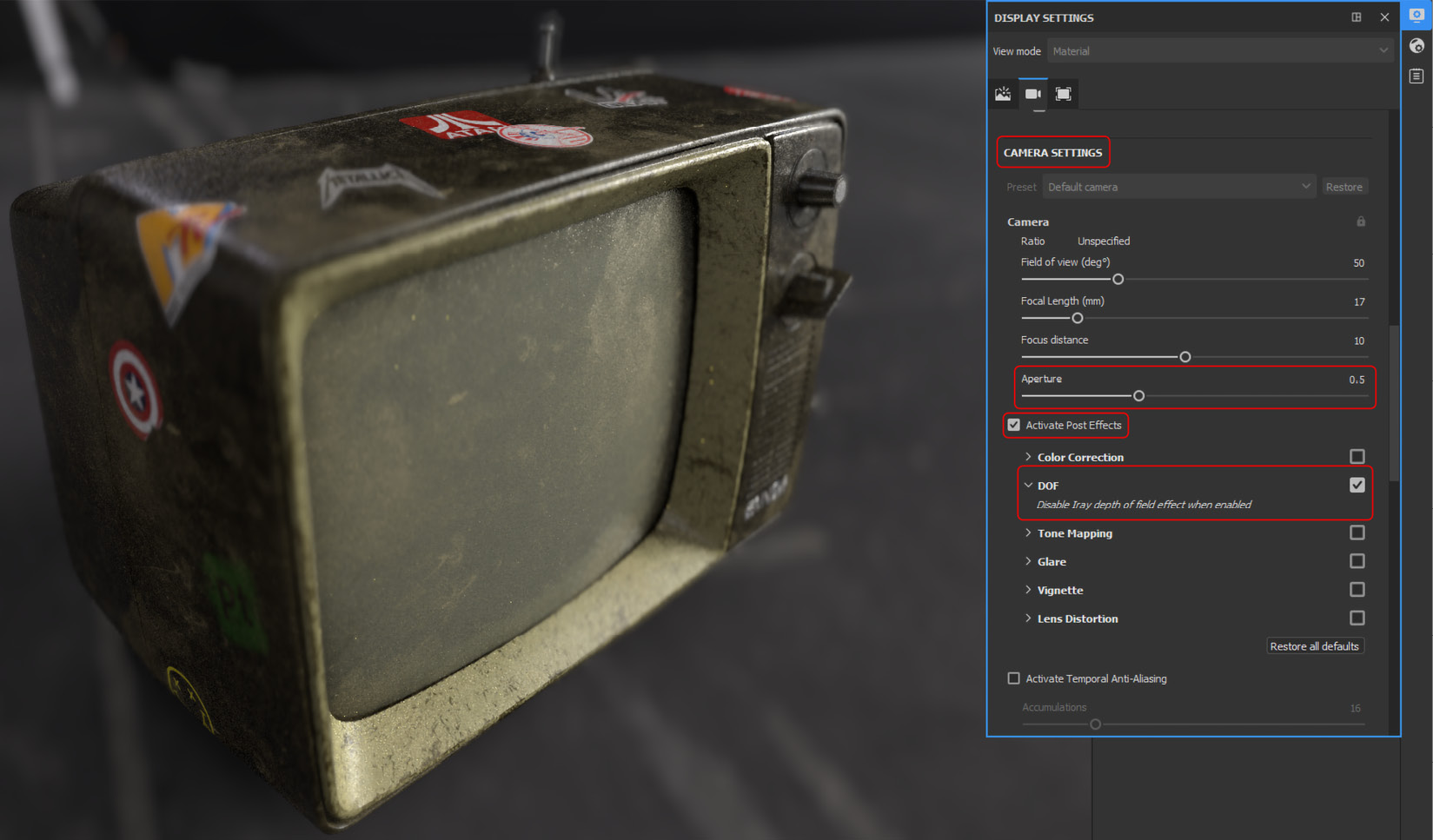
Figure 6.60 – Changing the Camera settings and Activate Post Effects
- Now, let’s do some color correction. First, we need to tick the Color Correction checkbox to activate it and then adjust the following settings:
Saturation: 0.75
Contrast: 1.003
Brightness: 1.2
Bias: 0
Sepia Tone Ratio: 0.15
White Balance Temperature (K): 6800
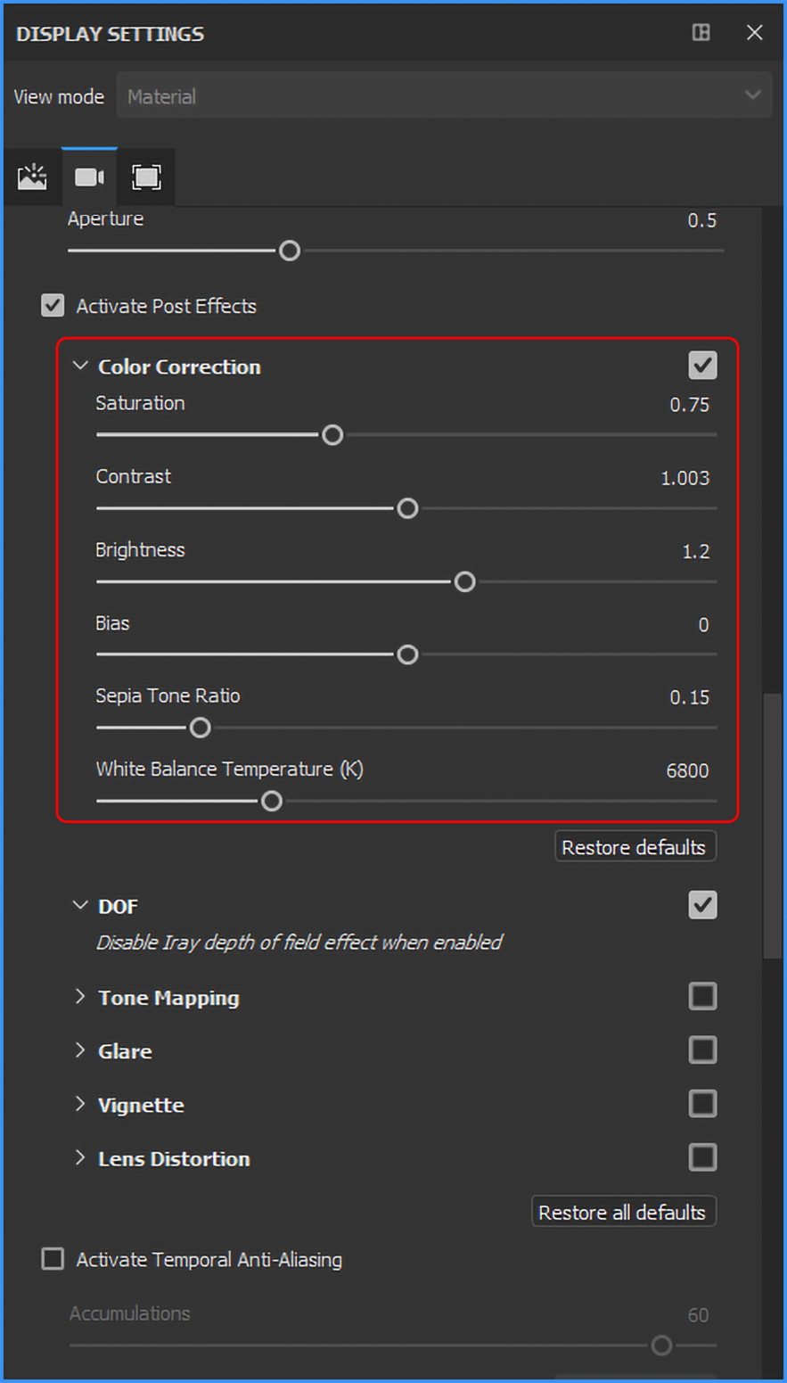
Figure 6.61 – The Color Correction settings
- The last effects that we will add are Glare and Vignette. First, you need to tick their checkboxes to activate them, and then adjust the following settings:
- Glare:
- Luminance: 0.6
- Threshold: 0.1
- Remap Factor: 2.75
- Shape: Filter Cross Screen
- Vignette:
- Strength: 0.3
- Glare:

Figure 6.62 – Adjusting the Glare and Vignette Settings
- There are a couple more settings in DISPLAY SETTINGS that you can try on your own. However, the final output after adding the DOF, Glare, and Vignette effects will look the same as shown in Figure 6.63.
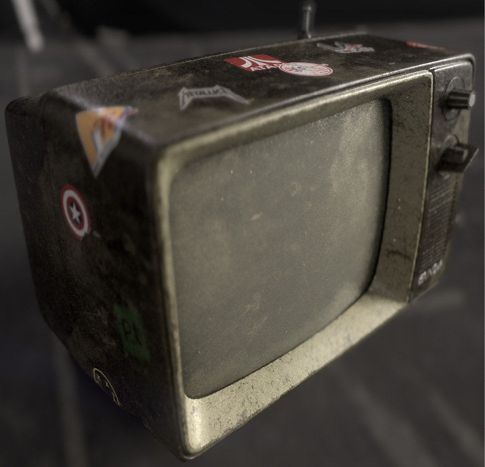
Figure 6.63 – The final output after applying effects
- Now, to up the quality of the render, you can either decrease Min Samples and increase Max Samples or increase Max Time. However, you have to compromise with the render time, owing to its higher quality. We will keep the existing samples and time settings; the rendering will stop when it reaches the assigned minimum and maximum samples or maximum time, whichever ends first.
- The size of the rendering image is the same as your viewport; however, you can change it with the Override viewport resolution option. Once you are satisfied with your render, you can save it as an image with your desired file type using the Save render option. Moreover, you can also directly upload it to your ArtStation account using the ArtStation Share option; however, some versions do not have this option.

Figure 6.64 – Rendering and saving the artwork
Summary
I am glad to announce that we are done with Adobe Substance 3D Painter part of this book, and we have finished learning about Adobe Substance 3D Painter. Now, you can confidently say that you know how to work with Adobe Substance 3D Painter, and after working for a few more weeks with this application, you will surely become a professional.
The Adobe Substance 3D Designer part of this book is about Adobe Substance 3D Designer, which is the industry’s go-to program for creating 3D materials. Substance 3D is used by over 95% of AAA gaming projects now in production, as well as the most famous visual effects and animation firms.
Substance 3D Designer is an application intended for creating 2D textures, materials, filters, and 3D models in a node-based interface. It heavily focuses on procedural generation, parametrization, and non-destructive workflows. You will learn Adobe Substance 3D Designer in detail in the next part.
As it is the longest-running application in the Substance 3D ecosystem, the resources made with it are the most versatile and dynamic possible.