″You can tell me the world is round, and I′ll prove to you its square
You can keep your feet on the ground, but I′ll be walking on air
You′re pretty good at waiting, while I go running around Well that′s just the way it is, you know.″
— ″HOLE IN MY POCKET,″ SHERYL CROW, C′MON, C′MON (A&M RECORDS, 2002)
Those waveforms appearing on the computer screen of any digital audio workstation sketch amplitude versus time. This chapter leaves the time axis well alone and focuses on the sometimes accidental and sometimes deliberate manipulation of the amplitude axis. Amplitude axis distortion represents a family of effects common in many styles of multitrack production. As many decades of rock and roll have shown, distortion is often sought out, deliberately created, and blatantly emphasized.
Consider an audio signal processor with a single input and a single output (Figure 4.1). While the device might be an effects device designed to distort, it might also be a power amplifiers, a mixing console, or some other signal-processing device. When the shape of the output waveform deviates in any way from the shape of the input, distortion has occurred. Comparing the detailed shape of anything but very simple waveforms seems difficult at first. Sine, square, sawtooth, triangle waves (see Chapter 1), and other simple periodic waveforms might be visually inspected to confirm a change in shape. Complex musical waves present a challenge.
The comparison of output to input is made easier by plotting the output amplitude versus the input amplitude. Figure 4.2 shows a device that simply passes the signal, without any amplitude change whatsoever. The output amplitude is identical to the input amplitude. Because every input value is matched by the exact same output value, this undistorted signal follows a perfect line on this plot, at exactly 45°.
![]() Figure 4.1 A device that distorts.
Figure 4.1 A device that distorts.
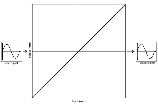
![]() Figure 4.2 Output amplitude versus input amplitude.
Figure 4.2 Output amplitude versus input amplitude.
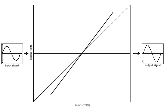
An amplifier that increases the gain without otherwise changing the shape of the waveform simply remains on a straight line, but deviates from the 45° angle (Figure 4.3). The amplitude is consistently scaled up or down in value.
Distortionless unity gain occupies the 45° line. Devices that increase level without distortion are described by lines steeper than 45°. Devices that attenuate without distortion are described by lines shallower than 45°. By preserving the same waveform shape, the output versus input plot remains a straight line. For this reason, a device that does not introduce distortion into the signal is said to be linear.
![]() Figure 4.3 Output amplitude versus input amplitude for linear gain.
Figure 4.3 Output amplitude versus input amplitude for linear gain.
Recording engineers discover quickly in their careers that a signal cannot be raised in level without bound. All devices have finite capabilities to create amplitude. Each and every device in the recording studio reaches a voltage limit.
Consider a simple domestic light switch — a musical instrument only in the hands of a rare talent. Turn the switch on, and the full voltage supplied by the power company is applied to the light bulb. Flipping the switch harder or faster will not change this. Dimmers can effectively lower the average voltage fed to the light bulb. Barring the addition of other electronic components, the voltage may never be higher than that supplied to the input of the switch. That is the maximum voltage available.
Power amplifiers present a similar situation. The power amp is fed a line level audio signal. The voltage of that signal is magnified by the power amp and fed to the loudspeakers. That power amp is plugged into the wall. It receives the main′s power and converts it into internal power supply voltages. Those internal voltage rails represent the finite limit of voltage capability for the audio output. No matter what sort of voltage swing is supplied on the audio input to the power amplifiers, at some level the output can increase no further.
All audio devices, including mixing consoles, guitar amplifiers, and equalizers, possess an output voltage limit. It must be understood what happens when that limit is reached.
Hard Clipping
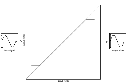
Consider a device that abruptly hits its output voltage limit (Figure 4.4). Below the point of distortion, there is no warning that the device will run out of output voltage capability. The threshold of distortion is crisp and absolute. The audio below this limit is completely undistorted. As long as the input remains below the threshold of distortion, the performance of the device is perfectly linear.
Send an input whose level seeks to drive the output above this limit, however, and the peak of the wave is flattened. A sine wave input leaves the device looking as if its peaks had been clipped off. The term for this kind of distortion, clipping, comes from a visual inspection of the output waveform. As the transition from linear to nonlinear is abrupt, it is classified hard clipping.
![]() Figure 4.4 Output amplitude versus input amplitude creating hard clipping.
Figure 4.4 Output amplitude versus input amplitude creating hard clipping.
Sine wave inputs below the threshold of distortion remain sine waves on output. Sine wave inputs of ever-increasing amplitude develop more severe clipping. Taken to an extreme (Figure 4.5), the output based on a sine wave input starts to resemble a square wave.
Severely clipping a sine wave until it resembles a square wave has the effect of adding harmonic content to the sine wave signal. That is, send a 100-Hz pure tone through a hard-clipping device and the squareish wave output is a signal that retains some energy at 100 Hz while shifting the rest of that energy up to 300 Hz, 500 Hz, and so on. The act of clipping a waveform essentially synthesizes harmonics, a phenomenon known as harmonic distortion. Hard clipping begins to introduce harmonics toward creating the square wave, which was shown in Chapter 1 to follow the equation:
A specific set of odd harmonics makes a square wave square. As the equation makes clear, a true square wave has the impractical requirement that an infinite number of harmonics are needed. When a device is driven into hard clipping, beware of the possibility of side effects due to the generation of a broad range of harmonics, possibly reaching into extremely high frequencies, even beyond what is nominally audible.
![]() Figure 4.5 Hard clipping a sine wave in to a square wave shape.
Figure 4.5 Hard clipping a sine wave in to a square wave shape.
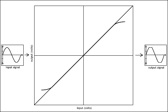
![]() Figure 4.6 Output amplitude versus input amplitude creating soft clipping.
Figure 4.6 Output amplitude versus input amplitude creating soft clipping.
Soft Clipping
Clipping is not always so abrupt. Imagine a device that approaches its amplitude limits more gradually (Figure 4.6). There may not be a well defined threshold of distortion that separates the distorted from the undistorted. As inputs are raised in level, the degree of output shortcoming gets worse too.
This type of distortion also alters the peaks of the waveforms, but in a kinder, gentler way than hard clipping. Call it soft clipping. As the output versus input plot makes clear, soft clipping is nonlinear. It is a kind of amplitude distortion. The peaks are squeezed down, not lopped off. Distortion of a different shape is, not surprisingly, built of a different recipe of harmonics.
By way of analogy, physicists are fond of placing a mass on a spring in a frictionless world. The spring remains linear if not overstretched (i.e., no distortion). If stretched too far, the opposing force of the spring starts to rebel and overreact (i.e., soft clipping). If the spring is stretched so far that the mass bumps into the floor, motion is instantly stopped (i.e., hard clipping). Pressure waves in air can reach similar limits. Voltage oscillations in audio equipment suffer the same indignities.
Asymmetric Distortion
Distortion containing even-order harmonics leads to asymmetry in the output versus input plot, as in Figure 4.7. A sine wave input is modified as shown, with a different shape below zero versus above zero. The simple triode tube gain stage favored in the preamp section of an electric guitar amp often offers this type of distortion.
It is a common misconception that soft clipping comes from even harmonics and hard clipping from odd harmonics. Both hard and soft clipping are in fact made entirely of odd harmonic distortion. Even harmonics will lead to asymmetric traits like that shown in Figure 4.7.
4.1.2 INTERMODULATION DISTORTION
The discussion above, evaluating the spectral changes to a sinusoidal input into a device reaching its amplitude limits is not the whole story. Nonlinear devices have a more profound effect on complex signals. That is, when an input contains energy at more than one frequency, the harmonics generated are not just limited to the odd and even multiples of each frequency component. These harmonics are created, to be sure. But additional frequency components, not harmonically related to the input spectrum, are also created. Called intermodulation distortion, energy at frequencies related to the sum and difference of the spectral components appears at the output of the distortion device.
![]() Figure 4.7 Assymetric amplitude adds distortion.
Figure 4.7 Assymetric amplitude adds distortion.
An input containing two frequencies, f1 and f2, would develop distortion components at frequencies equivalent to f1 + f2. The differences between frequency components on input lead to distortion artifacts at the arithmetic sum of these frequencies. Similarly, distortion will be found at the differences, such as f1 - f2 and f2 - f1.
Depending on the degree of nonlinearity of the distorting device, inter-modulation components between the harmonics may also develop. That is, harmonic distortion of frequency f1 leads to multiples of f1, such as 2f1, 3f1, and so on. Sum and difference distortion products built on these harmonics may become significant. This leads to distortion that is still more spectrally complex, containing terms such as 2f1 - f2, 3f1 - f2, 2f2 - f1, 3f2 - f1, etc.
When spectrally-rich signals are subjected to clipping of any kind, harmonic and intermodulation distortion must be anticipated.
Components of analog circuits such as transistors, transformers, and tubes each exhibit a characteristic type of distortion. Assemble them into various circuit designs and a new type of nonlinearity results. In the digital domain, algorithms may be written to reshape the signal in almost any way desired as headroom is exhausted. The types of nonlinearities are as diverse as the number of people who write the code and design the circuits. Audio systems utilizing these circuits, plus magnets, coils, ribbons, and optical components possess an output versus input behavior that grows more complex still.
Think of hard clipping and soft clipping as two icons of harmonic distortion, but recognize that analog and digital devices can develop unique combinations and variations of distortion that are a complex result of the overall design and layout of the components and algorithms employed.
Some audio devices are purpose-built to distort (guitar amps, guitar amp simulators, and distortion pedals), offering a unique flavor that comes from the combination of harmonics associated with a device′s output versus input shortcomings.
Other types of audio equipment possess some kind of distortion more as a side effect. Transducers, compressors, tube gain stages, and analog magnetic tape are among the more notable examples. The devices have other design goals. A microphone must convert acoustic pressure changes into electrical voltage changes, a loudspeaker must convert electrical voltage changes back into air pressure changes, a compressor automatically attenuates audio when the signal is above the specified threshold, etc. In addition to this nominal function, many of these devices also introduce harmonic and intermodulation distortions of varying types which may be taken advantage of by the clever recordist to further refine the sound quality of the audio signal at hand.
Musicians think of timbre as that attribute of sound that separates a piano from a guitar when they play the same note. Engineers must sort out what sonically separates a Steinway from a Bösendorfer among pianos and a Les Paul from a Telecaster among guitars, even as these instruments play the same note. Trained and careful listeners can reliably distinguish very fine properties of a sound. The unique distortion traits of each audio device in the studio endow that device with a sort of sound fingerprint related to distortion. Distorting devices, like fuzz boxes and tube amps, offer their own characteristic qualities of distortion. Some mixture of hard clipping, soft clipping, asymmetric, and other forms of distortion adds up to a distinct and possibly quite desirable sound quality. Any component, pushed beyond its linear limits, offers harmonic and nonharmonic alterations to the signal passing through it that may impart a sonic flavor an engineer seeks.
4.3 Motivations for Distortion
This effect is not just for engineers. Distortion of the right kind is naturally sought out by musicians and music fans alike. Spared the pleasure of reading this text, guitarists, singers, and drummers still employ distortion as a method of musical expression. Fans of many, if not most, styles of popular music react positively to distortion almost instinctively. When a device is overloaded, something exciting must be happening. Someone is misbehaving. Rules are being bent or broken. Distortion in rock and roll is as natural as salsa in Mexican food. It is the caffeine of music. Or perhaps it is the garlic. Used musically, most people can not resist. Accordingly, audio engineers reach for distortion as a staple effect.
Beyond the visceral, distortion has practical benefits. Distortion can influence an engineer′s use of the fader. Augmenting a sound with additional, spectrally-related energy likely makes that sound easier to hear (see Chapter 3). In this way, distortion becomes a creative alternative to the more obvious approach of simply pushing up the fader to make it louder. Any single track of a multitrack project fighting to be heard in a crowded mix can achieve distinct audibility through the harmonic lift that comes from at least a little well-chosen distortion.
Distortion offers the engineer an alternative to the more straightforward spectral effect of equalization (see Chapter 5). The fact that amplitude limitations create spectral complexity means that an engineer can reshape timbre in surprising, complicated, and glorious ways through distortion. Equalization, as discussed in Chapter 5, emphasizes and deemphasizes spectral regions present in the signal being processed. Distortion fabricates entirely new spectral components, fodder for further manipulation in the multitrack production.
Two ways to create a square wave are made clear. First, it may be synthesized through the addition of a large number of strategically chosen sine waves, each at just the right frequency with just the right amplitude, diligently following Equation 4.1. Alternatively, a square wave may be created through the hard clipping of a sine wave. The history describing the creation of the square wave does not matter. A square wave is a square wave. In both cases, a waveform looking and sounding like that shown in Figure 4.8 results. Each and every square wave of the same fundamental frequency has the same spectral recipe, whether they were deliberately put there in an additive synthesis effort to build a square wave or they were the inevitable result of hard clipping of a sine wave.
Consider a complex wave with pitch, such as an electric guitar track. Far from a pure tone, electric guitar contains energy at a range of frequencies. Make this the input to a device that distorts. Each and every harmonic component of that timbrally-rich input triggers its own set of clipping related harmonics. Sum and difference components between energy components at all frequencies also appear. The spectral content spreads upward in frequency as harmonics are generated, and spreads further outward up and down in frequency as intermodulation components gain amplitude. Distortion can make a complex signal significantly more complex.
![]() Figure 4.8 A 100-Hz square wave.
Figure 4.8 A 100-Hz square wave.
The engineer interested in the creative use of distortion should keep a few trends in mind.
The harmonics generated by the distortion nearest to the frequency content of the original signal can be difficult to hear due to masking (see Chapter 3). The second harmonic may be especially difficult to hear due to the additional affect of the upward spread of masking into this frequency range.
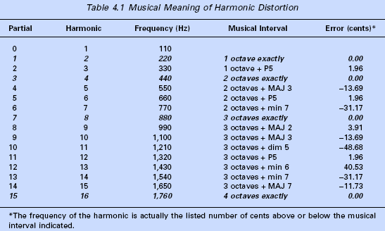
The musical meaning of the harmonic distortion components is important. If the recipe of distortion calls for energy at even harmonics (two times the frequency, four times the frequency, etc.), they form musically-consonant intervals (multiples of the octave) with the source waveform. Odd harmonics (three times the frequency, five times the frequency, etc.) form more dissonant intervals. Table 4.1 shows the approximate musical meaning of harmonic distortion. Note the relative consonant harmony associated with the even harmonics. Three of the first four even harmonics have octave-based relationships with the fundamental. The second, fourth, and eighth harmonics fall exactly on a multiple of the input frequency. The intervening sixth harmonic is also quite consonant in the harmony of the fundamental, falling exactly two octaves plus one perfect fifth above it. The odd harmonics not only appear at more dissonant intervals, but also possess pitches that are detuned from these intervals by many tens of cents versus equal tempered tuning. The distortion associated with even harmonics can be more pleasing to the ear, just adding musically-sensible, high-frequency emphasis. The distortion associated with odd harmonics can sound harsher, creating a stronger effect that stands out more.
The harmonic energy associated with distortion can cause masking of other signals. That is, a vocal that had been perfectly intelligible and a snare drum that formerly cut through the mix can both become more difficult to hear when distortion is added to the electric guitar. Spectral masking is very much in play (see Chapter 3). Distortion, like equalization, must be strategically used. Guitar processing affects not only guitar, but also those instruments that occupy similar spectral regions, after distortion.
More aggressive clipping generally increases the amplitude of distortion components. Distortion can become easier to hear as the energy associated with the clipping is increased. Three phenomena are at work:
- Each individual harmonic increases in amplitude.
- Harmonics of ever-higher frequencies are introduced.
- Intermodulation components grow in amplitude with the harmonic components.
When harmonic distortion is used as an effect, the engineer must be aware that the spectral result is the generation of harmonics above and below all the spectral components of the source waveform, not just the fundamental. Distinguishing one element of a multitrack production with a thoughtfully chosen type of distortion may cause unwanted masking of other signals fighting to be heard in those spectral regions now occupied by distortion harmonics. The thoughtful engineer listens for these possible side effects and makes only strategic, not opportunistic, use of distortion.
Artist: Green Day
Song: ″Boulevard of Broken Dreams″
Album: American Idiot
Label: Reprise Records
Year: 2004
Notes: Tremolo enhanced distorted guitar (see Chapter 7) is a hook here. The introduction reveals a quarter note burst of distortion over a sixteenth note amplitude modulating pulse. Most of the tone of the guitar is removed, leaving the harmonics associated with the distortion in plain view. This leaves plenty of room spectrally for the vocal, the snare, the bass, the acoustic guitar, and the piano. Then when the full guitars come in later, it is huge!
Artist: The Rolling Stones
Song: ″Sympathy for the Devil″
Album: Beggars Banquet
Label: ABKCO
Year: 1968
Notes: An iconic guitar solo sound whose unique guitar tone is built on aggressive distortion. An otherwise thin, piercing tone commands respect through this sonic barbed wire.
Artist: U2
Song: ″Zoo Station″
Album: Achtung Baby
Label: Island Records
Year: 1991
Notes: While distortion can be applied to any track, the lead vocal is the rare target here, sitting front and center, with the first words sung on the album. Do not miss those tasty fragments of distorted drums in the intro too.
Song: ″Pride and Joy″
Album: Texas Flood
Label: Epic Records
Year: 1983
Notes: Not the only song and guitarist, but this distorted tone is a touch-stone for every guitarist who tries to play the blues.
Artist: The Wallflowers
Song: ″One Headlight″
Album: Bringing Down the Horse
Label: Interscope
Year: 1996
Notes: Lead vocal gets emotional lift through aggressive distortion in the chorus. Chorus harmonies get an even stronger dose; hard clipping is a significant part of this flavor of distortion.
