
You’ve already seen some of the ways GNS3 can interact with other software and operating systems. In this chapter, you’ll delve deeper into the advanced features of GNS3 and explore how you can expand your projects by interacting with additional Quick Emulator (QEMU) virtual devices and software.
Knowing about technologies such as Cisco’s ASAs, Intrusion Detection Systems/Intrusion Prevention Systems (IDSs/IPSs), and IOS-XR broadens your view of Cisco and GNS3 and can be useful when choosing a network certification path. Plus, it’s a lot of fun to play with virtualized Cisco products that are otherwise inaccessible to most people. It’s also important to learn how to use some of Cisco’s GUI-based tools.
I’ll begin by showing you how to install Cisco Configuration Professional (CCP) software, a web-based alternative to configuring routers via the Cisco command line interface. Next, you’ll learn how to configure and run an ASA. I’ll discuss using Cisco’s Adaptive Security Device Manager (ASDM) software, which is similar to the CCP software mentioned earlier but used to configure ASAs. By the end of the chapter, you’ll learn that patience is not only a virtue but a prerequisite when you set up a Cisco IDS/IPS. Finally, I’ll show you how to configure and use Cisco IOS-XRv devices in GNS3.
Most engineers use IOS commands to configure routers and switches, but there are other ways. CCP is a web-based alternative that uses “smart wizards” to simplify router configuration, and it provides tools to help you monitor and troubleshoot networks and VPNs. In a nutshell, CCP allows less experienced users to get their equipment up and running.
To use CCP with GNS3, you’ll create a simple project using one router and a VirtualBox virtual machine running Microsoft Windows, as in Figure 8-1. Although there are other methods to do this, I’ve chosen to demonstrate this method because it should work on any PC that’s running GNS3 (Windows, Linux, and OS X).
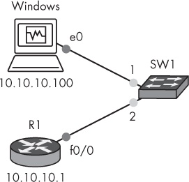
Log on to the Windows computer and disable the firewall to ensure that CCP has unrestricted communication with your router. (This isn’t mandatory, but it may prevent headaches later.) Assign the Windows guest an IP address on the same subnet as your router (in this example, 10.10.10.100).
Next, create a basic configuration on your router.
➊ R1(config)# ip http server
  R1(config)# ip http secure-server
  R1(config)# ip http authentication local
➋ R1(config)# username admin privilege 15 secret cisco
  R1(config)# interface f0/0
➌ R1(config-if)# ip address 10.10.10.1 255.255.255.0
  R1(config-if)# no shutdown
You need to enable the router’s web server ➊, create a user with full EXEC mode privileges ➋, and assign an IP address to the interface ➌. In this example, the router is assigned IP address 10.10.10.1.
Note
You have to create a Cisco admin account with full EXEC mode privileges (privilege 15) so that later you’ll have sufficient rights to configure the router using CCP.
After configuring the router, test connectivity between the Windows guest and the router using a ping command.
C:> ping 10.10.10.1If you can successfully ping the router, then it’s safe to proceed. If you cannot ping the router, check your IP addresses and interfaces.
CCP is a Java-based application that interacts with a web browser, so before you begin, download and install Java if you don’t have it already (http://www.java.com/). Make sure you also have the latest version of Adobe Flash Player (http://www.adobe.com/). You can download Cisco Configuration Professional from the Cisco website (http://www.cisco.com/).
To install CCP, log on to your Windows virtual machine and launch the setup program; you should see the CCP installation wizard. Click Next and follow the instructions to complete the setup.
Launch Cisco Configuration Professional by right-clicking the program icon and choosing Run as Administrator. When the program opens, you’ll be asked for the IP address of a router you want to manage. You should see the CCP Device Manager, shown in Figure 8-2.

Enter the IP address you assigned to the router (10.10.10.1), enter the administrator username and password you assigned earlier (admin and cisco), and then click OK. After logging on, you should see the CCP management screen, shown in Figure 8-3.

Before you can manage your router, you have to select it by first clicking the router hostname R1 ➊ and then clicking Discover ➋ so CCP can discover its features and capabilities. After it’s been discovered, you can set up your router by clicking Configure ➌ in the toolbar. The advantage of using CCP is that it guides you through the process of assigning IP addresses, NAT, VPNs, and other Cisco features without you having to know any IOS commands. Be aware that Cisco certification exams primarily focus on IOS commands, and not CCP, to configure devices.
Cisco’s ASA is an improved version of the old PIX firewall. GNS3 emulates a Cisco ASA model 5520. Although it’s not a router, you may be surprised to learn that the ASA supports several routing protocols, including RIP, EIGRP, and OSPF, allowing you to easily network them with other GNS3 routed devices.
Before you can use an ASA virtual machine with GNS3, you need an image file of the ASA operating system. The fastest way to get an image of the ASA operating system is to copy it from an ASA you already own (that is, from the ASA installation CD or directly from an ASA device). Copying files from a Cisco ASA works the same way as copying files from a Cisco router: you can use FTP or TFTP. In this example, you’ll use a TFTP server. There are plenty of free TFTP servers to choose from, so find one you like and install it on your PC.
After you have a TFTP server running on your network, log on to your physical ASA and copy your ASA image file to your PC. In the following listing, my ASA image file is named asa824-k8.bin, and my TFTP server is running on a PC at IP address 192.168.1.100:
ciscoasa# copy flash:asa824-k8.bin tftp
Address or name of remote host []? 192.168.1.100
After you have an ASA image file, you need to make some modifications to the file before you can use it with GNS3.
The Cisco ASA is really just a small Linux PC, and ASA image files like asa824-k8.bin contain a compact Linux operating system designed to run on ASA hardware.
The image file includes a Linux kernel and other support software for the appliance. To run the ASA software using GNS3, you have to unpack the .bin file, make some modifications, and repack it in a way that’s suitable for QEMU. Fortunately, there are plenty of clever people in the Linux and Cisco communities who have written image unpacker software that does this for you. You can download Cisco Image Unpacker for Windows from the GNS3 website, or you can use a Linux shell script like repack.v4.sh. Regardless of which unpacker you choose, you’ll need to find one designed for your version of ASA software. After running the script, you should be left with two files: asa-vmlinuz (a Linux kernel) and asa-initrd.gz (a RAM disk file). These are the files used by QEMU and GNS3.
If you don’t want to modify your own ASA image file, a quick Internet search should turn up plenty of ready-to-use ASA files. These images usually come in a .zip file that contains the two files (asa-vmlinux and asa-initrd.gz).
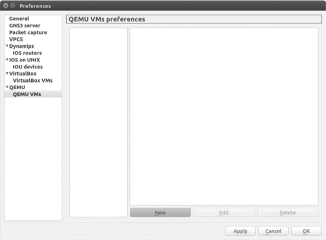
Before configuring an ASA in GNS3, check that QEMU is installed and tested on your PC. (See the QEMU installation information for your particular operating system in Chapter 6.) Next, launch GNS3, select Edit ▸ Preferences on Linux and Windows or GNS3 ▸ Preferences on OS X, and choose QEMU VMs from the panel on the left, as shown in Figure 8-4.
To create a new ASA in GNS3, click New to start the New QEMU VM wizard. Select ASA 8.4(2) from the Type drop-down menu, as shown in Figure 8-5.
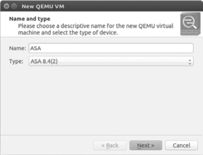
By default your device is automatically named ASA, but you can rename it whatever you prefer. When you’re done naming your ASA, click Next to continue.
The wizard should automatically locate and choose the correct QEMU binary file for your PC, as shown in Figure 8-6.
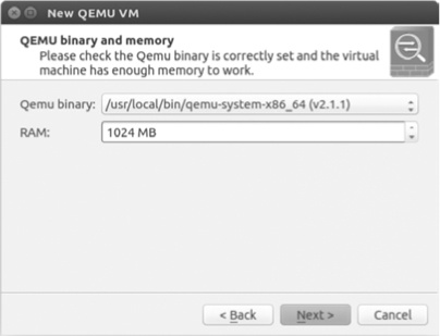
If it does not find a QEMU binary, verify that QEMU is installed correctly on your PC and try again. The default RAM value is 1024MB, but this is the minimum amount required to run the ASA image. You can increase the value by entering a new value in the field. When you’re done, click Next to continue the wizard.
The last step is to browse and select your initial RAM disk and kernel image, as shown in Figure 8-7.
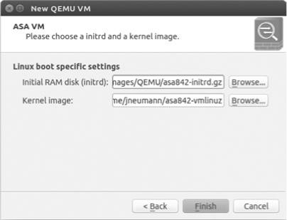
Set Initial Ram disk (initrd) and Kernel image to the correct files for your computer; these are usually named asa842-initrd.gz and asa842-vmlinuz, respectively.
When you’re done choosing the two images, click Finish to complete the installation. After successfully adding your ASA, the ASA device should be displayed in the QEMU VM Preferences window, as shown in Figure 8-8.

The current settings of your ASA should be displayed in the panel on the right, and one setting you should note is CPU throttling (located under Optimizations).
Unlike Dynamips devices, the ASA does not have an Idle-PC option to control CPU consumption. This means that an ASA can consume your entire CPU, much like a Dynamips router does when no Idle-PC value has been set. To prevent this, GNS3 uses another open source application (cpulimit) to adjust the maximum amount of CPU that a QEMU/ASA instance can consume. The default value is 80 percent, which works well in most situations. You can edit your ASA settings and raise or lower the value, but be careful; using too little of your CPU, by decreasing the percentage, can result in poor ASA performance and frequent ASA crashes, and setting the percentage too high can result in slower overall PC performance.
Another setting to note under Optimizations is the Process priority. The default value in GNS3 is low, but it can be set to low, medium, or high. The Process priority determines when the QEMU/ASA instance gets CPU time. Processes with a high priority gain access to the CPU before processes with a low priority. In general, changing the priority should have little or no effect on your system, but to be safe, keep it set to low to prevent your ASA from potentially overriding important system processes.
On Windows and OS X, the cpulimit program should have been installed with GNS3. On Ubuntu Linux you need to install cpulimit using the following command:
$ sudo apt-get install cpulimitNow that your ASA virtual machine won’t take over your system, let’s log on to an ASA and perform a basic configuration.
Drag an ASA firewall node from the Devices toolbar to your workspace. Your ASA should be located in the Security Devices section of the toolbar. Start the ASA and open a GNS3 console connection. While it loads, you should see standard ASA startup messages followed by the ASA command prompt:
ciscoasa>
A few error messages before the prompt are perfectly normal, but if your ASA fails to start or you see a lot of errors, check your settings or try a different ASA image file.
Note
It’s not uncommon for an ASA in GNS3 to hang or stall during the boot cycle, especially on older hardware. If this happens, stop and restart the ASA. It may take a couple attempts before you get a successful boot.
To test simple network connectivity, create a link from your ASA to another GNS3 device in your workspace. Next, open a console connection to the ASA and configure an interface with an IP address.
ciscoasa> enable
ciscoasa# configure terminal
ciscoasa(config)# interface GigabitEthernet0
ciscoasa(config-if)# ip address 10.10.10.1 255.255.255.0
ciscoasa(config-if)# nameif inside
ciscoasa(config-if)# no shutdown
After you’ve configured an interface, use a ping command to test connectivity from your ASA to other devices in your project.
Warning
Even with CPU throttling enabled, ASA devices are processor intensive, so you may want to use them sparingly in your projects, especially if you have a low-end PC.
After verifying that your ASA device is running properly, you’re ready to begin adding them to your projects. This can be helpful for learning how to configure the ASA or to prepare for a Cisco certification exam.
Cisco’s ASDM is similar to the CCP software that was covered in Cisco Configuration Professional, so many of the details are the same. Like CCP, ASDM provides a point-and-click Java-based web interface. The key difference between CCP and ASDM is that ASDM is designed to configure only the Cisco ASA, not other Cisco devices.
Before you install the ASDM software, create a project like the one in Figure 8-9. You’ll use the Windows virtual machine to install and run the ASDM application, and then you’ll launch ASDM and use it to take a look at the ASA.

There are two ways to acquire the ASDM software: copy it from the flash memory of a real ASA or find it online. After you have the ASDM software, it needs to be stored on your virtual ASA’s flash drive; from there you’ll install it on your Windows virtual machine PC using a web browser. I recommend Mozilla Firefox because I’ve found that it runs ASDM better than Internet Explorer. (Just be sure to disable any pop-up blockers and firewalls and install the latest version of Java.) You’ll also need FTP or TFTP server software to copy the ASDM software from the GNS3 Windows virtual machine to your ASA.
After you have an ASDM image, there’s some prep work to do on the ASA device so you can copy over the ASDM image. Enter these commands on the ASA:
  ciscoasa(config)# interface gigabitEthernet0
➊ ciscoasa(config-if)# ip address 10.10.10.1 255.255.255.0
  ciscoasa(config-if)# nameif inside
  ciscoasa(config-if)# no shutdown
  ciscoasa(config-if)# exit
➋ ciscoasa(config)# username admin password cisco privilege 15
➌ ciscoasa(config)# http server enable
  ciscoasa(config)# http 10.10.10.0 255.255.255.0 inside
Just like when you set up CCP, start by assigning an IP address to an inside interface ➊. Then, create a local user account ➋, and enable the HTTP server ➌.
After the ASA is configured and you have the ASDM software on your FTP or TFTP server, copy the software from your Windows virtual machine to the flash memory of the ASA.
ciscoasa# copy tftp flash
Source filename []? asdm-641.bin
Address or name of remote host []? 10.10.10.100
Destination filename [asdm-641.bin] <enter>
Accessing tftp://10.10.10.100/asdm-641.bin !!!!!!!!!!!
This example copies a file named asdm-641.bin from my GNS3 Windows virtual machine to my ASA device using TFTP.
After copying the ASDM file, you need to install the software on your Windows virtual machine. Launch your web browser and open an HTTP Secure (HTTPS) connection to the IP address of your ASA. You should be presented with a screen similar to Figure 8-10.

Because you’ll be using the Java Web Start option, click Run ASDM. Your PC should download Java software and present you with a few security warnings, which you can safely click past until you see the Cisco ASDM-IDM Launcher, shown in Figure 8-11.

Enter your ASA username and password (admin and cisco) and select OK to log on to your ASA. After you have successfully logged on, you can begin configuring the system from the ASDM Device Dashboard, shown in Figure 8-12.

The ASDM Device Dashboard includes several wizards that provide guided setups for creating common network and virtual private network (VPN) configurations. It also provides many real-time statistics to assist you in monitoring your network performance. Although not necessarily useful in GNS3, this information could be invaluable for maintaining a healthy network in real life.
The Cisco IDS/IPS identifies and prevents malicious activity on a network. In the real world, an IDS/IPS can be a stand-alone Cisco device or a module that you plug into an ASA or integrated service router.
Creating an IDS/IPS virtual machine for GNS3 is a real pain compared to most tasks, so before you begin, you may want to set aside a couple of hours.
Like PIX and ASA, IDS/IPS runs on special Linux software. If you own a physical IDS/IPS appliance, then an upgrade/recovery CD containing the software should have come with your device.
To install IDS/IPS using a QEMU virtual machine, you need an ISO image of the CD. You can create your own ISO image file using your CD or find one on the Internet. In this example, I used an IOS image file named IPS-K9-cd-1.1-a-6.0-6-E3.iso. Other versions of the software may work fine, but this version has proven to work well for creating a GNS3-compatible IDS/IPS.
IDS/IPS software runs using QEMU, so be sure you have installed it on your PC and have tested it with GNS3 before you begin. Then, create a build directory for your IDS/IPS and copy your ISO file to the directory. This is where you’ll create the IDS/IPS virtual machine.
To install IDS/IPS software on a QEMU virtual machine, you have to create two QEMU virtual hard disk image files. Open a terminal window and enter the following commands to create the images:
$ qemu-img create ipsdisk1.img 512M
$ qemu-img create ipsdisk2.img 4000M
Note
On Windows and OS X you may need to set your system path to include the location of your QEMU installation. Please refer to Installing QEMU on Windows and OS X for details.
Now that you’ve created the virtual disks, enter the following command to boot your virtual machine from the ISO image file:
$ qemu-system-i386 -hda ipsdisk1.img -hdb ipsdisk2.img -m 1024 -cdrom IPS-K9
-cd-1.1-a-6.0-6-E3.iso -boot d
On Windows systems, replace qemu-system-i386 in this command with qemu-system-i386w. After the system boots, you should see a screen similar to Figure 8-13.
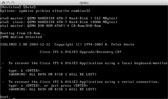
At the boot: prompt, enter k to perform a full system recovery. During the recovery process, your QEMU virtual machine will boot Linux from the ISO image, install a GRUB boot loader, and install the IDS/IPS software. When the install finishes copying files, the virtual machine will reboot automatically and end with a “FATAL” boot error message, as shown in Figure 8-14.

Don’t worry, this error is perfectly normal and expected. Quit QEMU and enter the following command to boot the IDS/IPS again:
$ qemu-system-i386 -name IPS4215 -hda ipsdisk1.img -hdb ipsdisk2.img -m
1024 -smbios type=1,product=IDS-4215 -net nic,vlan=1,model=e1000 -net
nic,vlan=2,model=e1000
The IDS/IPS virtual machine will boot to a Linux GRUB boot menu. At the boot menu, enter e to edit an entry. Use the arrow key to move down to highlight the kernel entry and enter e again to edit this entry.
Use the back arrow key to locate and change init=/loadrc to init=1. Press ENTER to accept the change and press b to boot from the modified GRUB menu. The system should now boot, bypassing the IDS/IPS startup, and bring you to a Linux console. From the console command line, you’ll use the vi editor to modify some IDS/IPS configuration files.
Note
You have to use the vi editor to modify files because no other editor is installed. If you are unfamiliar with vi, you’ll want to brush up on it before you continue. Just search for man vi online or enter man vi at the command line to view the man page.
After you’re familiar with vi editing commands, you’re ready to continue.
First, you’ll need to trick the IDS/IPS software into thinking your QEMU virtual machine is a real Cisco IDS-4215 Appliance Sensor. To fool the software, you have to modify two files: ids_functions and interface.conf. Modifying these files is pretty tedious, and the smallest mistake will prevent you from creating a working IDS/IPS device.
Start by entering the following commands from the shell prompt:
-sh-2.05b# /loadrc
-sh-2.05b# cd /etc/init.d
-sh-2.05b# ./rc.init
This will mount the Linux file systems used by the IDS/IPS and initialize the system. Next, use vi to open the ids_functions file.
-sh-2.05b# vi ids_functionsAfter opening the file, enter the command /845 to have vi locate the following entry:
elif [[ `isCPU 845` -eq $TRUE && $NUM_OF_PROCS -eq 1 ]]; then
        MODEL=$IDS4215
        HTLBLOW=8
        MEM_PAGES=${HTLBLOW}
        DEFAULT_MGT_OS="fe0_0"
        DEFAULT_MGT_CIDS="FastEthernet0/0"
Next, edit the elif statement and DEFAULT_MGT statements so they read as follows:
elif [[ 1 -eq 1 ]]; then
        MODEL=$IDS4215
        HTLBLOW=8
        MEM_PAGES=${HTLBLOW}
        DEFAULT_MGT_OS="ma0_0"
        DEFAULT_MGTCIDS="Management0/0"
When you’re finished editing and certain that you have made the correct changes, save the file and exit the vi editor.
Next, you’ll edit the interface.conf file.
-sh-2.05b# cd /usr/cids/idsRoot/etc
-sh-2.05b# vi interface.conf
Use the arrow key to move down to the section that begins with ####### IDS-4215 ########, modify each of the interface entries starting at [models/IDS-4215/interfaces/1] and ending with [models/IDS-4215/interfaces/6]. Each entry must look exactly like the following six entries:
[models/IDS-4215/interfaces/1]
name-template=Management0/0
port-number=0
pci-path=3.0
vendor-id=0x8086
device-id=0x100e
type=fe
mgmt-capable=yes
net-dev-only=yes
tcp-reset-capable=yes

[models/IDS-4215/interfaces/2]
name-template=FastEthernet0/0
port-number=1
pci-path=4.0
vendor-id=0x8086
device-id=0x100e
type=fe
sensing-capable=yes
tcp-reset-capable=yes

[models/IDS-4215/interfaces/3]
name-template=FastEthernet0/1
port-number=2
pci-path=5.0
vendor-id=0x8086
device-id=0x100e
type=fe
sensing-capable=yes
tcp-reset-capable=yes

[models/IDS-4215/interfaces/4]
 name-template=FastEthernet0/2
 port-number=3
 pci-path=6.0
 vendor-id=0x8086
 device-id=0x100e
 type=fe
 sensing-capable=yes
 tcp-reset-capable=yes

[models/IDS-4215/interfaces/5]
 name-template=FastEthernet0/3
 port-number=4
 pci-path=7.0
 vendor-id=0x8086
 device-id=0x100e
 type=fe
 sensing-capable=yes
 tcp-reset-capable=yes

[models/IDS-4215/interfaces/6]
 name-template=FastEthernet0/4
 port-number=5
 pci-path=8.0
 vendor-id=0x8086
 device-id=0x100e
 type=fe
 sensing-capable=yes
 tcp-reset-capable=yes
After you’ve finished editing the interfaces, scroll through the entries and verify that each interface is correctly configured. If you’re certain everything is correct, save the file and quit vi. Reboot the IDS/IPS virtual machine using the reboot command.
-sh-2.05b# rebootThe system should boot, configure a few things, and reboot again automatically. After the automatic reboot, immediately quit QEMU when you see the GRUB boot manager, shown in Figure 8-15. If you fail to quit and relaunch QEMU without using the proper options, the install will fail, and you’ll have to start over.
After quitting QEMU, restart your IDS/IPS virtual machine with the following command options:
$ qemu-system-i386 -name IPS4215 -hda ipsdisk1.img -hdb ipsdisk2.img -m
1024 -smbios type=1,product=IDS-4215 -net nic,vlan=1,model=e1000 -net
nic,vlan=2,model=e1000

Your IDS/IPS should now boot to the login prompt shown in Figure 8-16.
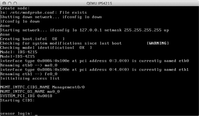
You’re almost done! Log on to the system by entering the default username cisco and password cisco, and you should be directed to reset the password. If any part of the IDS/IPS setup has gone wrong, you may see the message “UNSUPPORTED HARDWARE DETECTED,” as in Figure 8-17.
At this point, you could continue using the IDS/IPS virtual machine, or you could start over. I recommend you start over and create a new IDS/IPS until you can log on without errors. If you continue, the IDS/IPS system may produce further errors and not work as expected.

When you can log on without errors, you’re ready to continue.
The first time you log on to the IDS/IPS virtual machine, you will have to wait approximately 20 minutes or so while the system rebuilds its regex cache tables. This is normal even for an actual IDS/IPS appliance, and you should not interrupt it. You can check the progress periodically using the iplog-status command.
sensor# iplog-statusIf the status message reads “Error: getIpLogList: Analysis Engine is busy rebuilding regex tables. This may take a while.” then the system is still working and should not be interrupted. After the rebuild is finished, you should instead see “No IP logs available.”
When the rebuild is finished, enter the reset command to shut down and reboot the virtual machine. Unfortunately, there’s no elegant way to shut down the system. To avoid file corruption, you should quit QEMU when the reboot reaches the GRUB boot menu.
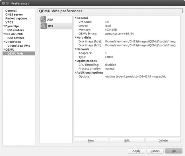
Adding an IDS/IPS to GNS3 is similar to adding an ASA. To add an IDS/IPS device, launch GNS3, select Edit ▸ Preferences on Linux and Windows or GNS3 ▸ Preferences on OS X, and select QEMU VMs from the sidebar, as shown in Figure 8-18.
To create a new IDS/IPS in GNS3, click New to start the New QEMU VM wizard. Select IDS from the Type drop-down menu, as shown in Figure 8-19.
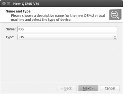
By default your device is automatically named IDS. Click Next to continue. GNS3 should automatically locate and choose the correct QEMU binary file for your PC, shown in Figure 8-20.
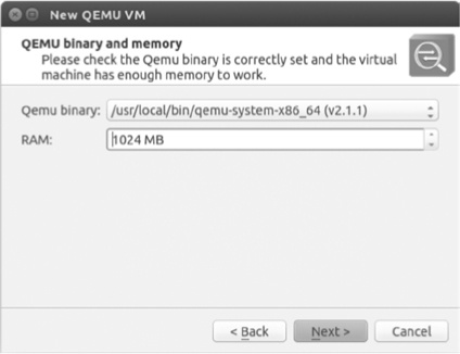
Set the RAM field to 1024 MB or greater, and click Next to continue to the Disk image (hda) selection, shown in Figure 8-21.

Browse and select the file named ipsdisk1.img that was created when you built your QEMU-ready IDS system. Click Next to continue to the Disk image (hdb) selection screen and choose ipsdisk2.img. Click Finish to complete the installation. You’re now ready to test your IDS.
To verify that your IDS/IPS is working, drag an IDS/IPS node to your workspace and start the device. GNS3 cannot open a console connection to an IDS/IPS device until after it has fully booted. This means you will not see any IDS/IPS messages prior to the login prompt. After the login prompt appears, you should be able to log in and configure the IDS/IPS. To prevent file corruption from occurring, use the reset command whenever you shut down the device.
After determining that your IDS/IPS is in good working order, you should make a backup copy of the QEMU disk image files. If something happens to your working IDS/IPS device, a backup copy of the files can save you hours of work later.
Cisco offers a version of IOS-XR in the form of a 32-bit virtual machine called IOS-XRv. The cool thing about IOS-XRv is that it’s not an emulator like IOU or NX-OSv. Instead, it’s a “hamstrung” version of IOS-XR that contains only a single route processor (RP). Network throughput is limited to 2Mbps, and there’s a hard-coded AAA user named cisco with the password cisco, making it impossible to use in a production environment, unless you want a slow and insecure network. Despite these limitations, the operating system includes management features, routing, and forwarding capabilities.
The software is designed to run using VMware ESXi or QEMU, making it a breeze to use with GNS3. If you have a Cisco CCO account, you should be able to download the software from the Cisco file exchange.
Cisco IOS-XRv files come in two image formats; the first is an OVA, and the second is a Virtual Machine Disk (VMDK) file. The OVA image (ending in .ova) is suitable for use with VMware ESXi; the VMDK file (ending in .vmdk) is ready to use with QEMU, and it’s the file you’ll use in GNS3. In this example, I’ll be using an image file named iosxrv-k9-demo-5.2.2.vmdk.
Adding an IOS-XRv device to GNS3 is pretty straightforward. You’ll launch the New QEMU VM wizard and follow the prompts; then you’ll edit the device, making a small change to increase the number of adapters. To add an IOS-XRv device, select Edit ▸ Preferences on Linux and Windows or GNS3 ▸ Preferences on OS X and then select QEMU VMs from the panel on the left. Click New to start the configuration and open the dialog in Figure 8-22.

Set Type to Default and enter a name for your device; I’ve entered IOS-XRv. When you’re finished, click Next to proceed to the QEMU binary and memory settings, shown in Figure 8-23.

IOS-XRv can run using 32-bit or 64-bit QEMU hardware emulation. Because I’m running a 64-bit operating system on my PC, I’ve chosen to use a 64-bit QEMU binary, named qemu-system-x86_64 (shown in Figure 8-23), and I’ve set RAM to 2048 MB, which is the recommended amount. However, if you run a 32-bit operating system, such as Windows, you’ll have to set the RAM to less than 2048MB. This is because the 32-bit QEMU program is unable to allocate that much memory to the IOS-XRv virtual machine. In this case, you should enter 1920 MB and use the drop-down menu to choose the QEMU binary named qemu-system-i386w.exe, as shown in Figure 8-24.

After configuring your QEMU binary and RAM, click Next to proceed to the Disk Image selection screen in Figure 8-25.

Click the Browse button to locate and choose your IOS-XRv .vmdk image file. I’ve selected a disk image named iosxrv-k9-demo-5.2.2.vmdk.
When you’re done selecting your image, click Finish to close the wizard. Next, select your newly created IOS-XRv device and click Edit. Select the Network tab and increase the number of adapters to 4. Click OK to close the window and then click Apply and OK to commit the change. You can set the number of adapters to whatever best suits your needs, but four should be suitable for most GNS3 projects.
Cisco IOS-XR is very IOS-like, but it’s not IOS. In this section, you’ll configure a simple project using one Dynamips router and one IOS-XRv device, shown in Figure 8-26.

You’ll use EIGRP to advertise three networks from router R1 to the IOS-XRv1 device. Finally, you’ll verify the routes using some IOS-XR commands. This is only a basic introduction to IOS-XR. If you truly want to learn IOS-XR, you’ll have to dig deep into Cisco’s documentation.
Begin by configuring router R1. Configure an IP address on the Ethernet interface that’s linked to IOS-XRv1.
R1# configure terminal
R1(config)# interface f0/0
R1(config-if)# ip address 10.1.1.1 255.255.255.0
R1(config-if)# no shutdown
Next, configure the three IP addresses on router R1’s loopback interfaces.
R1(config-if)# interface loopback1
R1(config-if)# ip address 172.16.1.1 255.255.255.0
R1(config-if)# interface loopback2
R1(config-if)# ip address 172.16.2.1 255.255.255.0
R1(config-if)# interface loopback3
R1(config-if)# ip address 172.16.3.1 255.255.255.0
R1(config-if)# exit
These addresses will be advertised to your IOS-XRv1 device using EIGRP. Finally, configure EIGRP and advertise all the networks.
R1(config)# router eigrp 10
R1(config-router)# no auto-summary
R1(config-router)# network 10.0.0.0
R1(config-router)# network 172.16.0.0
After you’ve finished configuring router R1, configure the IOS-XR device.
Log on to IOS-XRv1 and create a similar configuration to the one you created on router R1. You’ll configure an IP address and enable EIGRP to allow IOS-XRv1 and router R1 to exchange routing information.
➊ RP/0/0/CPU0:ios#
  RP/0/0/CPU0:ios# configure terminal
  RP/0/0/CPU0:ios(config)# interface GigabitEthernet 0/0/0/0
➋ RP/0/0/CPU0:ios(config-if)# ipv4 address 10.1.1.2/24
  RP/0/0/CPU0:ios(config-if)# no shutdown
  RP/0/0/CPU0:ios(config)# router eigrp 10
➌ RP/0/0/CPU0:ios(config-eigrp)# address-family ipv4
➍ RP/0/0/CPU0:ios(config-eigrp-af)# interface GigabitEthernet 0/0/0/0
➎ RP/0/0/CPU0:ios(config-eigrp-af)# commit
The first notable difference between IOS and IOS-RX is the command prompt. The IOS-XRv1 command prompt ➊ indicates that your context is the first route processor (RP/0/0/CPU0). Because this is a demo version of IOS-XRv, it’s limited to this single route processor.
Next, when an IP address is configured on an Ethernet interface, you have to specify the family of the IP address you’re using (IPv4 or IPv6), and the subnet mask is represented in CIDR notation (/24) ➋. Similarly, you have to specify IPv4 or IPv6 when configuring the EIGRP route process ➌. Lastly, you advertise networks by placing an IP-configured interface under the EIGRP route process ➍. When you’re done, be sure to commit your changes ➎.
Once you’ve configured everything, enter the show eigrp neighbors command, and you should see this output:
RP/0/0/CPU0:ios# show eigrp neighbors
IPv4-EIGRP Neighbors for AS(10) VRF default

H   Address                 Interface      Hold Uptime   SRTT   RTO  Q   Seq
                                           (sec)         (ms)        Cnt Num
0   ➊10.1.1.1            ➋Gi0/0/0/0      13 00:28:09   19    200   0   3
In a correct configuration, an EIGRP neighbor adjacency will form with router R1 at IP address 10.1.1.1 ➊ from interface Gi0/0/0/0 ➋.
Now, verify that all the 172.16.0.0 networks have been advertised from router R1 to IOS-XRv1 using the show route command.
RP/0/0/CPU0:ios# show route
--snip--

C    10.1.1.0/24 is directly connected, 02:58:51, GigabitEthernet0/0/0/0
L    10.1.1.2/32 is directly connected, 02:58:51, GigabitEthernet0/0/0/0
D   ➊172.16.1.0/24 [90/2570240] via 10.1.1.1, 00:43:21, GigabitEthernet0/0/0/0
D   ➊172.16.2.0/24 [90/2570240] via 10.1.1.1, 00:43:21, GigabitEthernet0/0/0/0
D   ➊172.16.3.0/24 [90/2570240] via 10.1.1.1, 00:43:21, GigabitEthernet0/0/0/0
All of the 172.16.0.0 networks have been successfully added to the IOS-XR routing table ➊. You can test connectivity by pinging one of the addresses.
  RP/0/0/CPU0:ios# ping 172.16.1.1
  Thu Oct 16 03:20:27.508 UTC
  Type escape sequence to abort.
  Sending 5, 100-byte ICMP Echos to 172.16.1.1, timeout is 2 seconds:
  !!!!!
➊ Success rate is 100 percent (5/5), round-trip min/avg/max = 9/19/49 ms
Here, the ping was 100 percent successful ➊. Now, save the configuration.
RP/0/0/CPU0:ios# copy running-config nvram:
Thu Oct 16 03:22:39.679 UTC
Destination file name (control-c to abort): [/running-config]? <enter>
Building configuration.
24 lines built in 1 second
[OK]
By now it should be obvious that IOS-XR is a little different from traditional IOS, but it’s also similar. IOS-XRv is a reliable platform, and it’s a lot of fun to play with in GNS3. Perhaps someday Cisco will port a version of IOS-XR from their carrier class routers down to their smaller commercial routers. If so, practicing with IOS-XRv in GNS3 will help prepare you for it.
Using GNS3, you can quickly become proficient at configuring and installing ASA firewalls. Having worked with Cisco gear for more than a decade, I’ve learned that ASAs are rock solid and work great for small network installations. Understanding how to configure the ASA is a must for anyone involved in small business networking. They’re one of the few nonenterprise Cisco products that are reasonably priced, feature rich, and easy to install.
Using ASDM, you can quickly configure an ASA to allow remote users to connect to their corporate networks through an IPSec VPN. Several cross-platform VPN clients are compatible with Cisco ASAs and routers; OS X has a built-in Cisco VPN client. On Windows, you have to install the Cisco VPN Client or Cisco AnyConnect software. On Linux, you can use Virtual Private Network Connection (VPNC), which works great. I use VPNC on a daily basis with Linux to access VPNs all across the country.
In the next chapter, you’ll look at Cisco IOU and learn how to integrate IOU devices into GNS3 projects. It’s an exciting new advancement that broadens the future of GNS3.