
CHAPTER 24
COMBINING GNSS AND TERRESTRIAL OBSERVATIONS
24.1 INTRODUCTION
![]() Ellipsoids define the mathematical shape of the Earth, or a portion thereof. Ellipsoids are commonly defined by the length of their semimajor axis, a, and the flattening factor, f. Commonly used ellipsoids are the Geodetic Reference System of 1980 (GRS 80) and the World Geodetic System of 1984 (WGS 84). Table 24.1 lists the length of the semimajor axis and flattening factor for these ellipsoids.
Ellipsoids define the mathematical shape of the Earth, or a portion thereof. Ellipsoids are commonly defined by the length of their semimajor axis, a, and the flattening factor, f. Commonly used ellipsoids are the Geodetic Reference System of 1980 (GRS 80) and the World Geodetic System of 1984 (WGS 84). Table 24.1 lists the length of the semimajor axis and flattening factor for these ellipsoids.
TABLE 24.1 Defining Ellipsoidal Parameters
| Ellipsoid | a (m) | 1/f |
| GRS 80 | 6,378,137.0 | 298.257222101 |
| WGS 84 | 6,378,137.0 | 298.257223563 |
A network of points determined with respect to each other on an ellipsoid is a reference frame, which is also called a datum. These reference frames define the geodetic coordinates of the points, and thus the origin and orientation of the datum. Most reference frames are regional in nature since the network of points only covers a portion of the Earth. These are known as local reference frames. For example, the North American Datum of 1983 (NAD 83) is a local coordinate system consisting of a network of points in Canada, the United States, Mexico, and some Caribbean islands. However, the International Terrestrial Reference Frame (ITRF) is an example of a global datum defined by a multitude of points located on all major land masses of the Earth. Similarly, the coordinates derived from the GNSS satellites are determined by a global network of tracking stations with coordinates defined in a global datum. Incorrectly stated, GPS is said to be using the WGS 84 datum. This statement should be interpreted by the reader as the datum defined by the global network of tracking stations that use the WGS 84 reference ellipsoid. The Department of Defense (DoD) has updated this network five times since its creation at the beginning of GPS weeks 730, 873, 1150, 1674, and 1762.
Besides their reference ellipsoid, reference frames differ in origin (translation), scale, and rotations about the three cardinal axes. Many modern local reference frames and global reference frames have nearly aligned coordinate axes and differ by only a few meters in their origins. These are known as Earth-Centered, Earth-Fixed (ECEF) coordinate systems. Thus, it is possible to use a three-dimensional coordinate transformation to transform points from a local datum to a global datum and back again. When using GNSS and absolute positioning techniques, the satellites serve as control points and all points determined by this method are defined in either the ITRF or WGS 84 datum depending on the source of ephemeris. However, this method of surveying is only accurate to the meter level. Thus, relative positioning techniques are generally used. However, if GNSS receivers are placed on control points defined in a local datum such as NAD 83, the resultant points are defined in a hybrid of the WGS 84 or ITRF and the local datum. The differences in these systems are generally at the centimeter-level. For lower-order surveys, these differences may not be of much importance. For high-order control surveys, they must be taken into account.
To combine GNSS and terrestrial observations, the control from two different reference frames must be reconciled. This can be done by transforming the local control coordinates into the GNSS reference datum, or by transforming the GNSS established points into the local datum.
As discussed in Chapter 18, a three-dimensional conformal coordinate transformation will take coordinates from one three-dimensional coordinate system into another. However, since the reference frames are nearly aligned, the rotational angles are generally in the millisecond range, which is very small. As will be shown in Section 24.2, the rotational process, as well as the entire transformation can be simplified since today's coordinate systems are nearly aligned.
To perform the transformation, coordinates of common points in both systems must be placed into their respective geocentric coordinate systems (see Section 17.4). Following this conversion, a least squares adjustment can be performed to determine the transformation parameters between the two systems. Once the transformation parameters are determined, the coordinates of any remaining points can be transformed.
For example, assume that an RTK-GNSS survey is being used to stake out a highway alignment, and that the highway alignment was designed using control points from State Plane Coordinate System of 1983 (SPCS 83).1 The real-time GNSS datum is defined by a set of DoD tracking stations using the WGS 84 ellipsoid, which has been made to closely approximate the International Terrestrial Reference Frame of 2008 (ITRF 2008). The geodetic control used in the State Plane Coordinate System is based on a series of National Spatial Reference stations in the United States, Canada, and Mexico using the GRS 80 ellipsoid. The NEH coordinates of the highway design stations must be transformed from the SPCS 83 coordinate system and orthometric heights to geodetic coordinates. The geodetic coordinates are then transformed to geocentric coordinates of (X, Y, Z)L in the local system. These points are occupied using a GNSS receiver and GNSS coordinates (X, Y, Z)G derived from satellite observations. Once three or more common points are occupied, the transformation parameters can be determined using a Helmert transformation, which is a simplification of the three-dimensional conformal coordinate transformation presented in Section 18.7. Following this, all GNSS-derived coordinates are transformed into the local coordinate system, and stakeout of stations can be performed.
24.2 THE HELMERT TRANSFORMATION
A local datum such as NAD 83 is an ECEF coordinate system. This means that the Z axis is nearly aligned with the Conventional Terrestrial Pole, X axis with the Greenwich Meridian, and the origin is at the mass-center of the Earth as derived by the datum points used in the definition. International reference frames such as the International Terrestrial Reference Frame use the same definitions for the axes, origin, and ellipsoid, but differ slightly due to the difference in the datum points used in its determination. Thus, the rotational parameters and translations between two ECEF coordinate systems are usually very small. The scale factor between two reference frames using the same units of measure should be nearly one.
Since the sine of a very small angle is equal to the angle in radians, the cosine of a very small angle is nearly one, and the product of two very small numbers is nearly zero, for two nearly aligned coordinate systems the three-dimensional conformal coordinate transformation presented in Equation (18.14) can be simplified as

In Equation (24.1) Δθ1, Δθ2, and Δθ3 are in units of radians and have been separated from full matrix by the addition of the unit matrix. The introduction of “Δ” indicates these values are differentially small.
The transformation of coordinates from one local datum to another datum is performed as
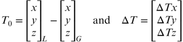
where s is the scale factor, XGD is the (x, y, z) coordinates from the global data (G) to be transferred into the local datum (L) and T the xyz translations necessary to make the origins of the two reference frames coincide. Similarly the scale factor, s, and translation parameters, T, can be modified as
In Equation (24.4), the approximate shift vector, T0, can be computed as
Since Equation (24.2) is nonlinear, a single common point or an average of all the common points can be used in Equation (24.5) to obtain initial approximations. For a single station, i, the linearized model for the corrections is
where

Example 24.1 demonstrates the mathematical relationship between the two reference frames for this limited set of points. This process should always be considered when combining traditional observations with GNSS coordinates for higher-order surveys. That is, if GNSS-derived coordinates are to be entered into an adjustment, they should first be transformed into the local datum. In the United States, the National Geodetic Survey has developed horizontal time-dependent positioning (HTDP) software,3 which allows the users to transform coordinates between several reference frames. This software transforms points for different epochs in time by also taking into account plate tectonics and applying velocity vectors to the parameters.
The process of transforming points from global reference frames to local reference frames is important when performing real-time satellite stakeout surveys, or trying to match coordinates from an earlier survey, which was performed using a different reference frame. A satellite survey implicitly uses the points located in a global datum. Since engineering plans are generally developed in a local datum such as NAD 83, the GNSS-derived coordinate values must be transformed into the local coordinate system. This process is known as localization (sometimes called site calibration) by manufacturers. From a design point of view, it is important to recognize that the best results will be obtained if points common in both reference frames surround the project area. After entering in the local datum coordinates, the GNSS receiver should occupy each station. The software then computes the transformation parameters and uses these to determine the coordinate values for the points to be surveyed or laid out. Section 24.5 discusses an alternative method used by manufacturers to accomplish this transformation.
24.3 ROTATIONS BETWEEN COORDINATE SYSTEMS
GNSS uses the geocentric coordinate system and provides baseline vectors in this system. Often, it is preferable to obtain the coordinate value changes in terms of geodetic coordinates. From geodesy, the relationship between changes in the geodetic coordinate system and the geocentric coordinate system is

where dx represents the changes in the geocentric coordinates, M the radius in the meridian, N the radius in the normal at latitude φ as given by Equation (23.16), h the geodetic height of the point, and RXG the transformation matrix.
The transformation between changes in the geodetic coordinate system and the local geodetic coordinate system are given in Equation (23.29), which is repeated here for convenience.

where RLG is the rotation matrix between the geodetic and local geodetic coordinate systems.
24.4 COMBINING GNSS BASELINE VECTORS WITH TRADITIONAL OBSERVATIONS
![]() As discussed in Chapter 23, the three-dimensional geodetic adjustment allows the adjustment of all traditional surveying observations. If the control is known in the local coordinate system, then Equation (24.2) can be included in adjustment to account for datum differences.
As discussed in Chapter 23, the three-dimensional geodetic adjustment allows the adjustment of all traditional surveying observations. If the control is known in the local coordinate system, then Equation (24.2) can be included in adjustment to account for datum differences.
Baseline vectors are the geocentric coordinate differences between two points. Thus, the translation component of Equation (24.2) is removed leaving only the scaling and rotational parameters. Therefore, the last three columns of the Ji matrix in Equations (24.6) and (24.7) can be eliminated leaving

Equation (24.10) can be used in Equation (24.6). However, since the three-dimensional geodetic network adjustment is performed in the local geodetic coordinate system, the rotational elements of Equation (24.10) can be transformed about a single station in this system. Dropping the Δ symbol, the rotation about the single station in the local geodetic system becomes
where θn is a rotation about the north axis of the local geodetic coordinate system, θe a rotation about the east axis of the local geodetic coordinate system, θu a rotation about the up axis of the local geodetic coordinate system, R1, R2, and R3 the rotation matrices defined in Section 18.7, and φ0 and λ0 the geodetic coordinates of the rotational point. This point should be picked near the center of the project area.
Again since in nearly aligned coordinate systems the rotations are small, the above rotations can be simplified to
where

I is a three dimensional identity matrix, θn, θe, and θu are in radian units, and φ0 and λ0 the geodetic coordinates of the rotational point.
Finally, the transformation going from the observed GNSS vector to its local geodetic equivalent between stations I and J is

where s represents the differential scale change between system 1 and 2, R is defined in Equation (24.12), [·]1 represents the GNSS baseline vector components in the local coordinate system, and [·]2 represents the GNSS observed baseline vector components between stations I and J.
In the preceding chapter, the three-dimensional geodetic network adjustment was developed in the local geodetic system. Thus, the addition of the GNSS baseline vectors into this adjustment requires that the coefficient matrix be rotated into the same system. Recall from Chapter 17 that the coefficient matrix (A) for each GNSS baseline vector consisted of three rows containing −1, 0, and 1. The matrix, as presented in Chapter 17, must be rotated into the local geodetic system. Thus, for the baseline vector IJ, the new coefficient matrix values are derived as
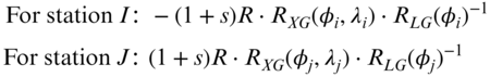
where s is the change in scale between the two systems, rotation matrix R defined in Equation (24.12), rotation matrix RXG defined in Equation (24.8), rotation matrix RLG defined in Equation (24.9), and (φi, λi) and (φj, λj) the geodetic coordinates from stations I and J, respectively.
When developing the matrices for a least squares adjustment, the unknown parameters for scale and rotation should be set to zero. After the first iteration these values will be modified and updated. At the end of the adjustment, these parameters can be checked for statistical significance, as was described in Section 18.8.
The elements of the coefficient matrix for the unknown rotation angles and scale are

where

24.5 ANOTHER APPROACH TO TRANSFORMING COORDINATES BETWEEN REFERENCE FRAMES
![]() The Helmert transformation discussed in Section 24.2 is the most rigorous method of converting between reference frames. However, many GNSS software manufacturers have broken this problem into their horizontal and vertical components. This method is especially useful when the local coordinates are in some arbitrarily created temporal coordinate system. To effect this transformation, the satellite-derived geodetic coordinates must be transformed into two-dimensional Cartesian coordinates through the use of a map projection system. Often, a stereographic map projection (see Appendix F.4) is used to convert the GNSS-derived latitude and longitude of stations into local coordinate system values of ne.
The Helmert transformation discussed in Section 24.2 is the most rigorous method of converting between reference frames. However, many GNSS software manufacturers have broken this problem into their horizontal and vertical components. This method is especially useful when the local coordinates are in some arbitrarily created temporal coordinate system. To effect this transformation, the satellite-derived geodetic coordinates must be transformed into two-dimensional Cartesian coordinates through the use of a map projection system. Often, a stereographic map projection (see Appendix F.4) is used to convert the GNSS-derived latitude and longitude of stations into local coordinate system values of ne.
The oblique stereographic map projection uses a plane as its developable surface. It is defined by its grid origin and scale factor. Typically, the average of the control station's latitudes and longitudes are used to define the origin of the projection. To minimize the scaling differences between the distances observed conventionally with those derived from satellites, the map projection coordinate system is brought to the surface using the average height of the project control. This is accomplished using a defining scaling factor for the map projection system of

where k0 is the scale factor used to define the oblique stereographic map projection, Havg the average orthometric height of the project, and Re the average radius of the Earth at the origin of the coordinate system.
The transformation process involves observing stations using a GNSS receiver that already has coordinates that are defined in the arbitrary/local coordinate system. The satellite-derived coordinates are then used to define the map projection system. Following this, the satellite-derived map projection coordinate values are transformed into the local coordinate system using a two-dimensional conformal coordinate transformation from Section 18.2. However, the general least squares approach may provide a better transformation since both systems of coordinates can contain observational errors. Using either method, the satellite-derived plane coordinates are brought into the local horizontal coordinate system. Subsequently, these transformation parameters are used to transform the remaining satellite-derived map projection coordinates into the aribtrary/local coordinate system.
Once the horizontal transformation is completed, the satellite-derived heights must also be transformed into local elevations. To do this, at least three points with known local elevations must be observed to determine their satellite-derived geodetic heights. These geodetic heights are then converted into orthometric heights using an appropriate geoid model and Equation (23.39) rearranged as
where H is the station's orthometric height, h the geodetic height, and N the geoidal separation determined from a geoid model for that station. These three points determine a level surface that is oblique to the surface as determined by the same points using their local orthometric height values. This obliquity is caused by deflection of the vertical (see Section 23.6) and is corrected by applying two rotations in the cardinal directions. A translation between the two systems completes the transformation. The linear transformation is computed as
where T is the translation between the two level surfaces, re and rn the rotations in the east and north directions, NGPS, EGPS, and HGPS, the satellite-derived local map projection coordinates of the stations having orthometric heights as determined by Equation (24.18) of HGPS, HLocal the local orthometric height of the station, and ![]() the residual error determined after the transformation.
the residual error determined after the transformation.
24.6 OTHER CONSIDERATIONS
Using procedures similar to those shown in Chapter 23 and Example 24.2, a combined adjustment of both terrestrial and GNSS baseline vectors can be performed. If GNSS-derived station coordinates are to be held, they must first be transformed in the local datum to ensure consistency with any local control stations. However, if GNSS-derived points are the only control in the adjustment, then the entire adjustment can be performed using the global datum that was used to reduce the GNSS observations.
In both chapters, the adjustments are performed in the local geodetic coordinate system. This system was chosen since defining standard deviations for control stations in the (n, e, u) system is more intuitive to surveyors than either the geodetic or geocentric coordinate systems. References in the bibliography at the end of this book contain procedures for combining GNSS and terrestrial observations using either the geocentric or geodetic systems.
PROBLEMS
Note: Partial answers to problems marked with an asterisk can be found in Appendix H.
- 24.1 Discuss what is meant by a local reference frame.
- *24.2 Discuss what is meant by a global reference frame.
- 24.3 How do local and global reference frames differ?
- 24.4 What is meant by the term localization?
- *24.5 Why is it important to localize a GNSS survey before staking out a highway alignment?
- *24.6 Using the Helmert transformation parameters derived in Example 24.1, derive the NAD 83 geocentric coordinates (in meters) for a point having ITRF 08 coordinates of (1160652.008, –4655693.197, 4188423.986).
- 24.7 Same as Problem 24.6, except for a station having geocentric coordinates of (1160398.043, –4655803.184, 4188935.609).
- 24.8 Using the accompanying data, compute the Helmert transformation parameters to take the coordinate values from WGS 84 to NAD 83.
NAD 83 WGS 84 Sta X (m) Y (m) Z (m) X (m) Y (m) Z (m) 100 1,160,097.952 −4,634,583.300 4,188,086.049 1,160,098.356 −4,634,583.248 4,188,086.233 101 1,160,285.844 −4,634,859.416 4,188,233.622 1,160,286.248 −4,634,859.364 4,188,233.806 102 1,159,986.652 −4,634,623.501 4,188,153.783 1,159,987.056 −4,634,623.449 4,188,153.967 - 24.9 Using the accompanying data, compute the Helmert transformation parameters to take the coordinate values from WGS 84 to NAD 83.
NAD 83 WGS 84 Station X (m) Y (m) Z (m) X (m) Y (m) Z (m) 1 1,097,860.137 −4,684,923.884 4,172,732.773 1,097,859.116 −4,684,919.481 4,172,728.847 2 1,099,114.170 −4,684,740.495 4,172,609.370 1,099,113.147 −4,684,736.092 4,172,605.444 3 1,097,936.268 −4,686,351.303 4,171,109.757 1,097,935.246 −4,686,346.899 4,171,105.832 4 1,098,941.388 −4,686,376.388 4,170,823.932 1,098,940.366 −4,686,371.984 4,170,820.007 - 24.10 Using the appropriate information from Table 23.3, Example 24.2, and the accompanying baseline vector data, determine the nonzero elements of the coefficient (J) and constant (K) matrices.
Baseline ΔX (m) ΔY (m) ΔZ (m) ED 35.2573 −368.067 −347.063 - 24.11 Same as Problem 24.10, except for the following data. The approximate geodetic coordinates for Station F are (41°18′39.7004″ N, 76°59′58.9973″ W, 312.731 m).
Baseline ΔX (m) ΔY (m) ΔZ (m) FB −149.874 −25.079 22.222 - 24.12 Same as Problem 24.10, except for the following data. The approximate geodetic coordinates for station G are (41°18′12.8871″ N, 76°00′11.2922″ W, 350.935 m).
Baseline ΔX (m) ΔY (m) ΔZ (m) GD −529.004 188.868 334.427 - 24.13 Using Station A as the central point in a project and the baseline vectors given in Problem 24.10, what are the first iteration coefficients for the transformation parameters?
- 24.14 Same as Problem 24.12, except use the baseline from Problem 24.11.
- 24.15 Same as Problem 24.12, except use the baseline from Problem 24.12.
- 24.16 List the steps outlined in Section 24.5 to localize satellite-derived geocentric coordinates into a local coordinate system.
- 24.17 Using the procedures discussed in Section 24.5 and the following data, determine the following:
- (a) Transformation parameters for the horizontal and vertical transformations.
- (b) Residuals of the transformed coordinates.
Satellite-Derived Coordinates Local Coordinates Station X (m) Y (m) h (m) E (ft) N (ft) h (ft) 1 −335.415 −280.544 40.3742 7405.583 6812.877 248.31 5 −624.878 −58.153 31.9864 6641.129 7734.808 221.29 22 202.292 17.357 40.7997 9342.342 7375.175 249.81 102 757.950 321.418 59.9799 11341.155 7944.178 312.56 - *24.18 Using the transformation parameters found in Problem 24.17, what are local coordinate values for a station with satellite-derived map projection coordinates of (–329.062, –29.321, 126.205) in units of meters?
- 24.19 Repeat Problem 24.17 with the following data.
Satellite-Derived Coordinates Local Coordinates Sta X (m) Y (m) h (m) N (m) N (m) E (m) H (m) A −2678.662 2175.270 88.760 −34.248 107,835.569 673,901.575 122.998 B 1191.073 3411.702 100.080 −34.278 109,111.331 677,758.273 134.357 C 2988.168 −2695.266 80.380 −34.318 103,023.357 679,617.475 114.692 D −1650.335 −2748.906 68.810 −34.275 102,922.409 674,980.006 103.080 E 150.457 −141.428 113.560 −34.284 105,547.975 676,754.013 147.837 - 24.20 Using the transformation parameters found in Problem 24.18, what are local coordinate values for a station with satellite-derived oblique stereographic map projection coordinates?
Station X (m) Y (m) h (m) N (m) 1 701.732 −470.057 102.330 −34.291 2 1026.075 −304.910 108.150 −34.293 3 1079.183 797.099 119.910 −34.290 4 1372.298 1028.858 120.440 −34.292 - 24.21 Using the procedures discussed in Section 24.5 and the following data, determine the following:
- (a) Transformation parameters for the horizontal and vertical transformations.
- (b) Residuals of the transformed coordinates.
- (c) Local coordinates for station 5.
Satellite-Derived Coordinates Local Coordinates Sta E (m) N (m) h (m) E (m) N (m) h (m) 1 −866.174 2,421.082 167.945 7,876.158 6,449.579 168.478 2 1,659.368 2,093.530 167.945 10,111.902 7,669.078 168.433 3 −1,369.529 −1,874.955 160.935 9,994.089 2,678.123 161.421 4 576.170 −2,639.451 164.288 12,017.579 3,203.297 164.725 5 23.468 −86.987 165.658
PROGRAMMING PROBLEMS
- 24.22 Develop software that solves Problem 24.9.
- 24.23 Develop software that solves Problem 24.19.