
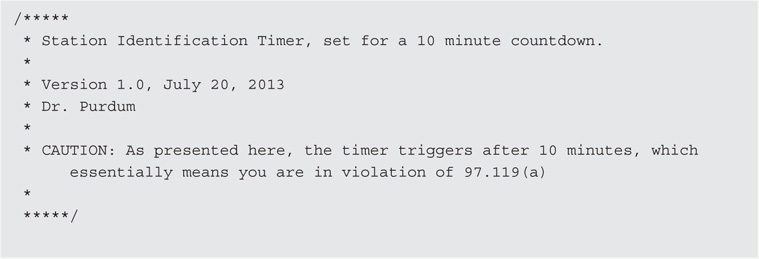
CHAPTER 4
Station Timer
In this chapter we use the LCD shield you built in Chapter 3 to create a station ID timer. Section 97.119(a) of the FCC Rules and Regulations that govern amateur radio operation states that:
(a) Each amateur station, except a space station or telecommand station, must transmit its assigned call sign on its transmitting channel at the end of each communication, and at least every 10 minutes during a communication, for the purpose of clearly making the source of the transmissions from the station known to those receiving the transmissions. No station may transmit unidentified communications or signals, or transmit as the station call sign, any call sign not authorized to the station.
We have all been guilty of breaking this rule at one time or another, usually because we simply lost track of time. Technically, it appears that those little transmission breaks often reserved for a “Yes” or “No” from the other operator are also in violation of 97.119(a). While we know of no incidents where the FCC has gone after a ham in violation of this section of the Rules, our license remains an earned privilege and there’s no reason to tempt Fate when it’s so easy to stay in compliance.
In this chapter, we present two station ID timers. The first timer is purely a software-defined timer. That is, you use the program to determine the time lapse between station ID times by reading one of the Atmel timers buried within the μC chip. The software uses the LCD display from Chapter 3 to create a countdown timer. When the timer determines that 10 minutes have passed, the display shows a warning message. A simple reset button recycles the clock.
The second station ID timer is a combination of software and hardware, using the DS1307 Real Time Clock (RTC) chip (see Figure 4-1). The RTC module can be purchased online for less than $5, or you could build your own from the chip. However, if you value your time at more than 10 cents an hour, these small modules you can purchase are a better choice. The RTC module uses the Inter-Integrated Circuit interface (I2C), which is a serial bus invented by Philips for connecting various modules to an electronic device. The I2C interface is easy to use and there are a ton of sensors and other devices that use the interface. It’s an interface worth knowing. The Arduino IDE and supplemental libraries provide most of the software used by the RTC timer.
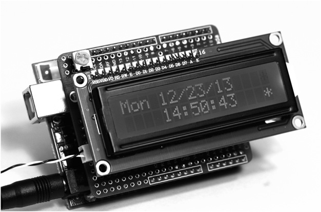
FIGURE 4-1 Real time clock/timer shield.
Software Version of ID Timer
In this section we present the station ID timer program that you can load and run with your LCD shield. The program displays an initial count of 10 minutes and counts down to 0 at which time it displays a message stating it’s time for you to identify yourself on the air.
The purpose of this section of the chapter is to show you some software design tips and techniques that you can use to improve your programming skills. If you are not interested in programming, you can skip the following sections of this chapter and proceed to the RTC section of the chapter. We recognize that not everyone is interested in the software that drives any given project … that’s just the way it is. What follows, however, is a program that works fine as written in its first draft mode, but can be improved with just a few minor tweaks. It’s those tweaks that we concentrate on in the rest of this section of the chapter.
The LCD timer program is presented in Listing 4-1. Version 1.0 of the program was written around midnight on a Saturday night just to see if we could get it working before we hit the sack. We did.
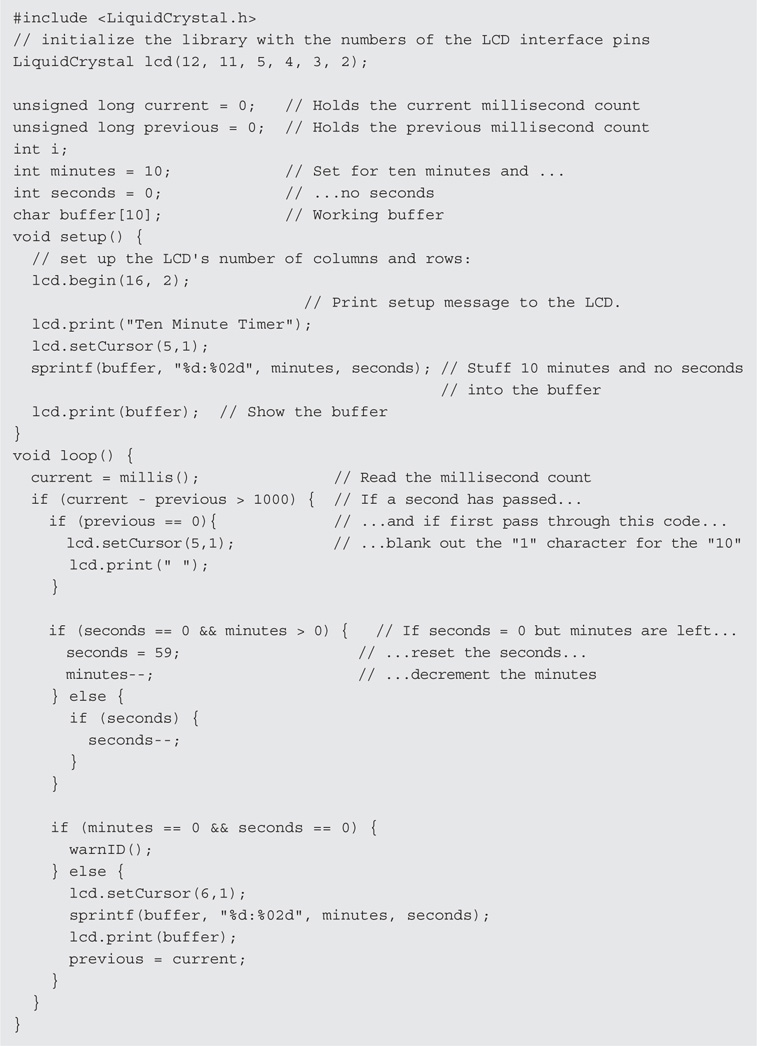
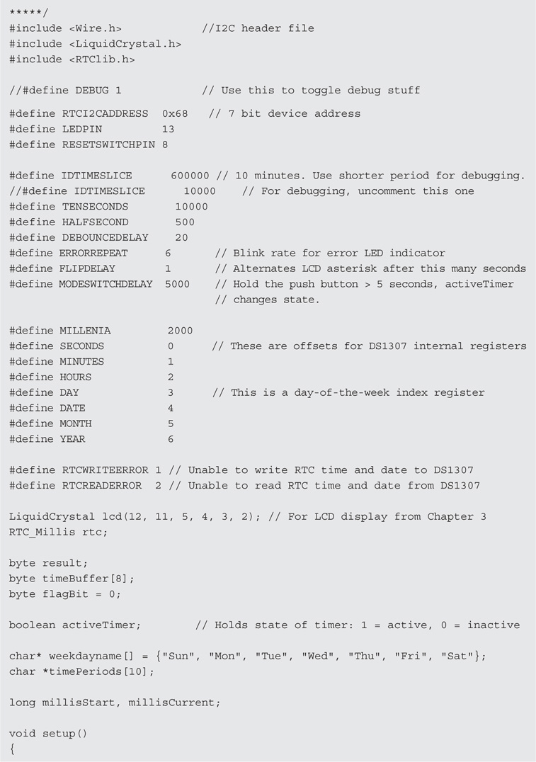
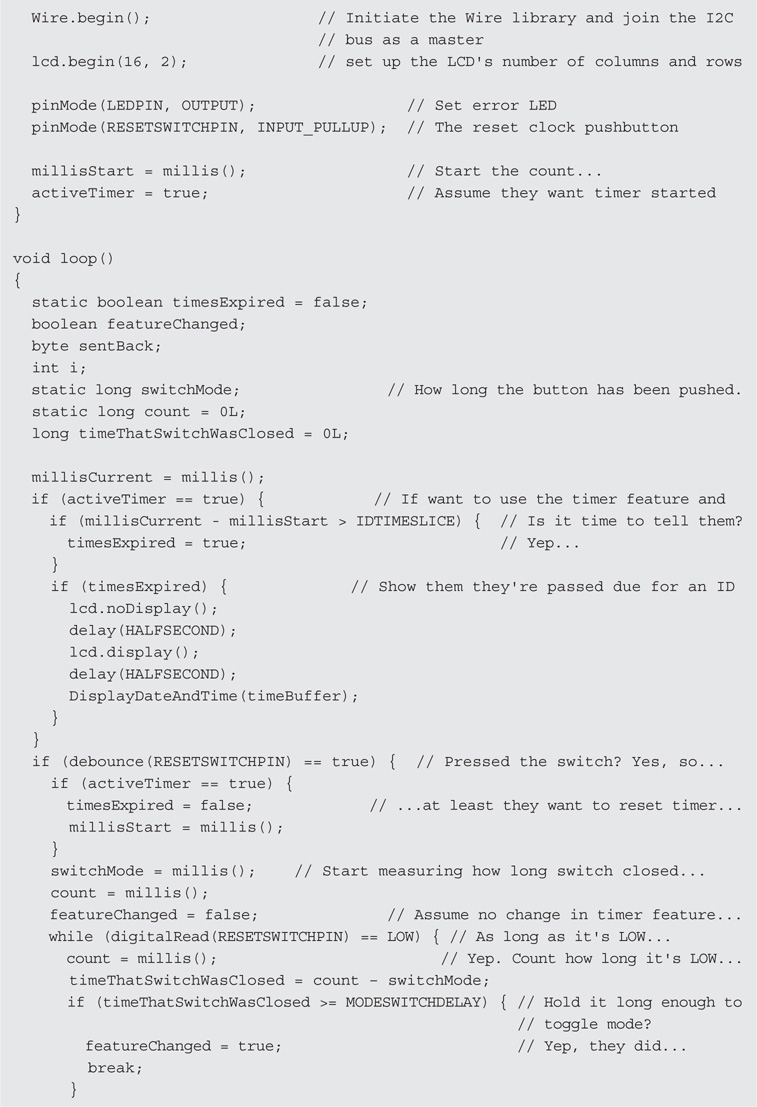
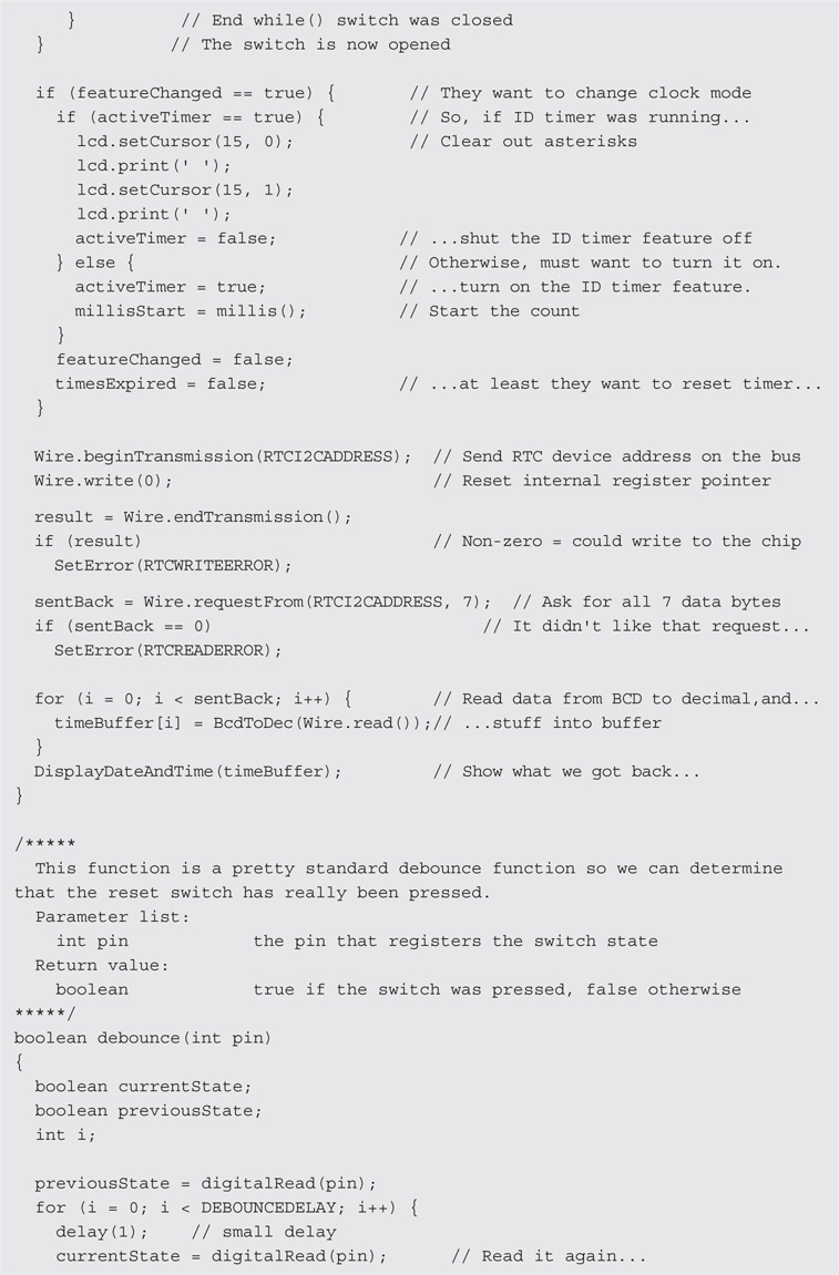
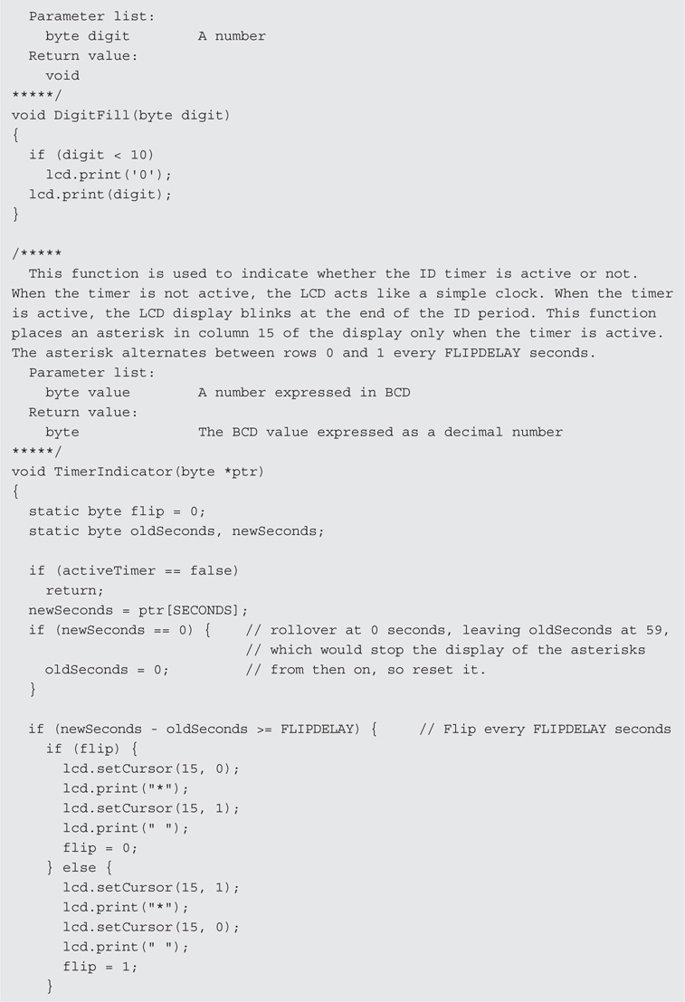
LISTING 4-1 The LCD timer program, version 1.0.
As mentioned earlier, the code worked the first time after correcting a few minor hiccups. When compiled on an ATmega168, the compiled program occupied 4526 bytes of program space. All in all, not too bad and, as the old saying goes: “If it ain’t broke, don’t fix it.”
Well, maybe … maybe not.
Magic Numbers
Good programmers don’t like magic numbers. So, exactly what is a magic number? Simply stated, a magic number is a number that appears in a program yet you have no clue what it means or why it’s there. There are lots of magic number statements in Listing 4-1, some bad, others not so bad. Extracting those magic numbers and classifying them, we might get something like the following list:
List of Bad Magic Number Statements
List of Not So Bad Magic Number Statements
lcd.setCursor(5,1);
seconds = 59;
While researching for this book, we found this statement in a program all by its lonesome:
delay(247);
Really? 247? And not a hint as to why it’s 247. We know the delay() function is passed a parameter expressed in milliseconds. Therefore, if it were 250 (i.e., a quarter of a second) perhaps we might make some informed guess about its value, but 247? At the present time, it’s even money that it’s either some kind of adjustment for the number of clock cycles to execute the delay or it’s the programmer’s parking spot number.
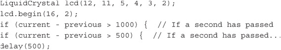
Bad magic numbers are so classed because we really don’t know why they have the value that they do. The first bad statement (LiquidCrystal lcd(12, 11, 5, 4, 3, 2);) is actually explained in the comment at the top of Listing 3-1 in Chapter 3, so it’s bad simply because we got lazy and didn’t copy the program comment header. The second bad statement is also explained in Listing 3-1, so again, it’s our laziness. The next three statements are bad simply because we have to pause a few nanoseconds longer than we should to figure out what the statement does. Note that, even though two of the lines have comments, the comments are the same, but the numbers are different. Sometimes a misleading comment is less helpful than no comment at all. Duplicate comments are especially common when doing cut-and-paste type of editing.
The List of Not So Bad statements are classed as such because we can pretty quickly figure out what they mean because of the use of a good method name (e.g., setCursor()) or a good variable name (e.g., seconds). The remaining bad magic numbers, 1000 and 500, need to be fixed.
Preprocessor Directives
There are a number of statement lines that can benefit from further explanation. The first time you saw examples of the #include preprocessor directive was in Chapter 3. Because we are using the shield you built in Chapter 3, we must include the LiquidCrystal header file that links us into that library in the program.
While header files and their associated library files are useful, they still don’t solve our magic numbers problem.
Fixing Bad Magic Numbers: #define
While you already understand what the #include preprocessor directive is, we still have to deal with our bad magic numbers. The fix involves a technique that uses the C preprocessor.
Clearly, the value 1000 is being used in the program to compare millisecond counts. Because 1000 milliseconds is the same as 1 second, we write the following statement near the top of the program, just after the include statement (preprocessor directives must appear in the source code file before any executable program statements):
#include <LiquidCrystal.h>
#define ONESECOND 1000
Because the #define begins with a sharp symbol (#), we know it, too, is a preprocessor directive. The #define preprocessor directive causes the compiler to search through the program source code and, every time it finds the characters ONESECOND, it substitutes the value 1000 in its place.
Your response at this point might be: So what? Well, which would you rather read if you’re trying to fix a program:
if (current - previous > 1000)
or
if (current - previous > ONESECOND)
If we add another #define:
#include <LiquidCrystal.h>
#define ONESECOND 1000
#define HALFSECOND 500
then the statement:
delay(HALFSECOND);
becomes that much easier to read and understand. If you use the #define with a little thought, it helps document what your program is doing. We should also mention that you do not have to use capital letters, but most programmers use the convention of capitalizing the letters for a #define. But that’s not the only advantage to using #defines in your programs.
Many years ago Jack was working on code that figured out fines for speeding tickets. The program had three different base fines for cars ($50), light trucks ($65), and tractor trailer trucks ($100) plus additional sums for each mile per hour over the speed limit. At the time, the speed limit for cars and light trucks was initially 55 mph and 50 for big trucks. The program contained codes like the following code fragment all over the place:
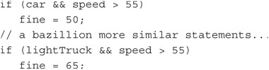
Then the laws changed and speeds were increased for cars to 70 mph, 65 for light trucks, and 60 for big trucks. Now what do you do? Well, really lazy programmers simply do a global search and replace 55 with 70. This is bad because phone numbers like 555-1234 (and similar numbers) get changed to 705-1234. (Always remember: Computers have the native intelligence of a box of rocks.) A slightly better plan is do a global search for 55 and see if the statement found pertains to a car or light truck (or even something else) and decide how to change the statement. Either way, this search-and-replace approach is a very error-prone process.
Instead, what if the programmer had avoided the magic numbers from the outset and used the following instead:
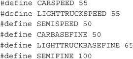
After the new law change, our smarter programmer takes about a minute and changes the #defines to:
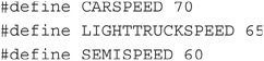
recompiles the program, and … Shazam! Everything is fixed. If the law happened to change the fines as well as the speeds, it would be equally easy to fix those because the code was written as:
![]()
The #define preprocessor directive should be used for most magic numbers, especially if there’s a chance it may change in the future. Creating symbolic constants using #defines makes program code easier to read, program changes faster to implement, and employs much less error prone process for change.
A Second Way to Remove Magic Numbers: const
As a general rule, if a #define is used to replace a numeric constant, it has no effect on the program size. Indeed, our test program remains at 4526 bytes. However, a #define preprocessor directive is not the only way to get rid of a magic number. We should also mention that you could also define a constant with the same effect, such as:
const int CARSPEED = 55;
The const keyword tells the compiler to flag the variable named CARSPEED as a constant and don’t let its value change anywhere in the program. As a general rule, you can use the const keyword before any regular data type (e.g., byte, int, long). This approach brings the same advantages to the table as does the #define preprocessor directive.
So, which method is better? When it comes to memory usage, both produce identical program sizes. If you use capital letters for constants, too, both stand out in the program equally well. However, if the Arduino IDE ever gets a true interactive debugger, using const does produce an entry in the symbol table where a #define does not. Also, you can perform type checking on a const variable but #defines are normally typeless. Because of these advantages, many programmers prefer to use the const keyword for constants, using capital letters to flag them as symbolic constants. However, after using the C preprocessor for symbolic constants for more than 30 years, these old dogs will likely stick with the #define.
Fixing Flat Forehead Mistakes
If you look carefully at Listing 4-1, you can see the statement:
int i;
a few lines after the #include preprocessor directive. The statement defines a variable named i for use in the program. Truth is, we thought we would need a loop counter, so we added the data definition during the initial code writing stage. However, if you look closely through the code, you discover the variable i is never used in the program. This is what we call a “flat forehead mistake.” You know, the kind of mistake where, once discovered, you pound the heel of your hand into your forehead and ask yourself how you could be so careless. Relax, we all make these mistakes. As you get more and more programming experience, the flat forehead mistakes all but disappear. (Alas, you often move on to bigger, more sophisticated mistakes.)
So, what’s the harm of one defined, albeit unused, variable in a program? Actually, not much. In fact, the Arduino compiler is smart enough to notice that we never used the variable so it never generated the code to create or manage the variable. The program size remains at 4526 bytes even after removal of the unused definition statement for variable i. That’s not to say that some other type of unused data definition won’t affect program size. Still, it’s sloppy to leave such unused data definitions in the code and they should be removed if for no other reason than they add unnecessary clutter to the program.
Encapsulation and Scope
Simply stated, encapsulation is the process of hiding your data from outside forces as much as possible. For example, consider the following statements that appear near the top of Listing 4-1:

Because these data items are defined outside of any function or other statement block, they are accessible and may be used by any program statement at any point in the program. There are several different types of scope associated with data definitions. Data that are useable everywhere in a program are said to be global data and have global scope. Data defined outside a function body is given global scope by the compiler. It’s not too much of a stretch to think of “visibility” or “accessibility” as synonyms for scope. In other words, a variable with global scope can be seen and used by virtually any other statement in the program.
In Chapter 2 you learned about the setup() and loop() functions. If you define a variable inside the setup() function, like:
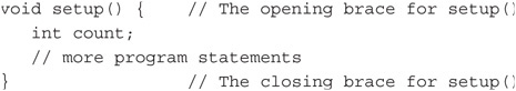
you can see that the variable named count is defined within the opening and closing brace of the setup() function. This means that the variable count has function scope. Function scope means that any data item defined within a function body can be used only within the confines of that function. Think of the braces as creating a black box named setup() and anything outside of setup() has no clue what’s going on inside the black box. Outside the setup() function, for all intents and purposes, count doesn’t even exist. If you tried to access count outside of setup(), the compiler would issue an error message saying the variable was “not declared in this scope.” All of the data defined within setup() function body, as marked by the opening and closing braces, are invisible outside that function. You can access count everywhere within setup(), but not outside of setup()’s definition.
So why bother encapsulating, or hiding, your data? You hide your data for the same reasons medieval kings hid their daughters in the castle tower … to keep other people from messing around with them. If all of your data have global scope and all of a sudden one variable has a screwy value, you have no idea where to begin looking for the program error because it could be at any point in the program. However, if something goes haywire with variable count in the example above, you know it has to be something within the setup() function that’s causing the problem. You know this because no force outside of setup() even knows the variable exists. Because you have encapsulated variable count within a function, your search for the error is narrowed from the entire program to a single function. While encapsulation may not seem a big deal in a program as simple and short as that in Listing 4-1, we have worked on programs with over 800,000 lines of code and any help we can get from a good design is welcomed.
Therefore, as a general rule, limit the scope of your data as much as possible. For Listing 4-1, it means moving the following data definitions from outside any program function:
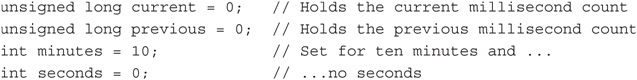
so they appear inside the loop() function. (We deleted the definition of i because we never used it.) Upon recompiling the program after the data definitions have been moved, the program size dropped to 3962 bytes for a decrease in program size of 564 bytes, or a little more than 12%.
That’s the good news.
The bad news is that our program no longer works correctly. It starts as before, showing 10 minutes of time and counts down to 9:59 and then never changes the display after that. When a program doesn’t do what it’s designed to do, we say we have a program bug.
We have a program bug.
Fixing Our Program Bug
Recall from Chapter 2 that the loop() function is called over and over until either the power is removed from the board or there is some kind of component failure. If you look at the statements in the loop() function in Listing 4-1, you can find the statement:
if (current - previous > ONESECOND) { // If a second has passed…
This expression means we need to use the previous and current millisecond counts and compare the difference between the two variables to ONESECOND. However, because loop() now looks like:
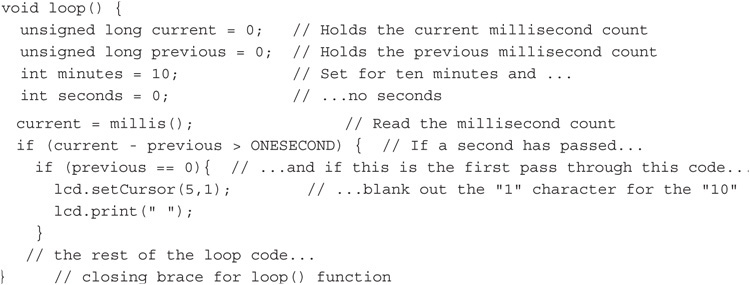
each time the statements within loop() are executed on each pass through the loop, variables current and previous are re-initialized to 0, so the statement:
if (current - previous > ONESECOND) { // If a second has passed. . .
can never be true. Not good. We want to encapsulate current and previous inside of loop(), but doing so prevents the variables from ever having any value other than 0 on each pass through the loop. We can go back to global scope and sacrifice the benefits of encapsulation, or we can encapsulate the data and have a program that doesn’t work properly. A true dilemma … two choices, both bad.
The static Data Type Specifier
Let’s make a small change to each data definition within loop() and see what happens. Place the word static at the front of each data definition in loop(), so the data definitions look like:

and recompile, upload, and run the program. Taa-daa! The program works as it should again … but why? The reason is because the keyword static causes the compiler to treat the data definitions differently.
When the compiler sees the keyword static in a data definition, it’s as though you placed the definition of the variable at the very beginning of the program … even before the statements in the setup() function are executed. If the variables are defined with initial values, as we have done here, the compiler assigns those values into the respective variables. Once the compiler has defined and initialized a static variable, it never redefines or initializes a static variable again.
What this means is that static definition statements are processed at program start and are then ignored from that time on. In our program, therefore, it’s like the definitions for current, previous, minutes, and seconds are defined outside of loop(), but their scope is limited to being known only within loop(). We now have the best of both worlds: we have encapsulated those variables inside of loop() … no other part of the program has direct access to them, but they retain their previous values on each new pass through the loop.
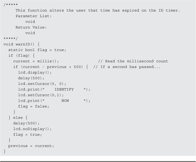
We also simplified the WarnID() function to just use a delay() function call. The delay() function is not the best choice in most cases because it literally shuts everything down on the Arduino board during the delay period. However, in this simple program example, we might use it because once the flashing message is read, the operator must hit the Reset button to restart the program anyway. The final version of the code, which is now 4382 bytes, is presented in Listing 4-2.


LISTING 4-2 The LCD timer program, version 1.1.
The code presented in Listing 4-2 is our final version of the software ID timer program. For now, we encourage you to experiment with the code presented in Listing 4-2. The changes don’t have to be earth-shaking, just something that makes a small difference in the way the program functions. You can always start over, so there’s no reason not to give it a try. One change that probably should be made is to issue a warning message when there are only 30 seconds or so left in the 10-minute countdown. After all, the user needs some time to make the station identification. Another addition might be to add a small buzzer to the circuit and activate it when time runs out, or just blink the display.
Using a Real Time Clock (RTC) Instead of a Software Clock
The software countdown timer as presented in Listing 4-2 works, but we can improve on it a little. It would be nice, for example, to have the LCD display serve both the function of a station ID timer as presented in Listing 4-2, but show the current date and time, too. Making these improvements does cost a little more (i.e., less than $5), but does augment the functionality of the timer. Plus, you’ll get to learn a few new things along the way … always a good thing.
The Inter-Integrated Circuit (I2C or I2C) Interface
The first new thing we want to discuss is the I2C interface. The I2C interface was developed by Philips Semiconductor (now known as NXP) back in the 1990s to allow low-speed peripherals to be attached to an electronic device. The interface was embraced by other companies that produced electronic sensors and other devices. While use of the interface has been license-free since 2006, NXP still licenses I2C slave addresses (explained below) used by the interface. The I2C interface is also called the Two Wire Interface (TWI), for reasons that become clear in a few moments.
The interface is actually pretty simple. I2C uses two wires to form a “bus” between electronic devices. The wires are referred to as a “bus” because it can connect more than just two devices together. One device serves as the “Master Device” and is responsible for establishing the communication on the bus. One or more “Slave Devices” are attached to the bus. Each of these slave devices is assigned a slave address that identifies the device on the bus. While both 8- and 16-bit addressing is available, most μC devices use the 8-bit addressing. The slave address for our RTC using the DS1307 chip is 0×68. Therefore, any time the address byte on the bus is 0×68, we know that it is the RTC that is involved in the communication that is taking place on the bus.
Both the master and slave have the ability to transmit and receive data on the bus. The data are sent on the SDA line shown in Figure 4-2. The speed, or pace, of the communications on the bus is dictated by the clock used on the bus. (Line SCL in Figure 4-2.) While there are several different clock speeds defined for the I2C bus, the most common are the 10kbits/s (low speed mode), the 100kbit/s (standard speed mode), and the 400 kbits/s (fast mode). Because of the way the clock is used to strobe the data on the line, actual data transfer rates are less than the mode speeds would suggest. The address space and bus capacitance limit the effective length of the bus to about 5 ft or so. (μCs have WiFi shields available that allow much greater communication links if needed.)
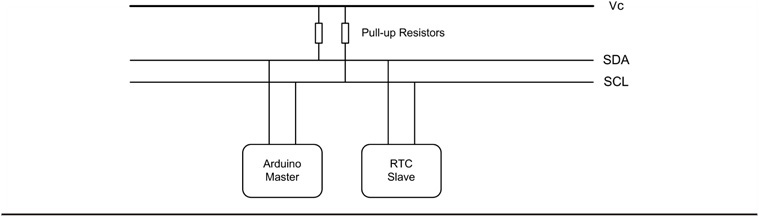
FIGURE 4-2 The I2C bus.
As a general rule, the SDA and SCL lines each need a “pull-up” resistor on them. The purpose of a pull-up resistor is to pull the voltage up to the logic high state (5 V for the Arduino) needed for the I2C interface to work properly. The actual resistor values are not critical, with values between 4.7K and 20K being common. Our circuits use 10K resistors because we had a bunch of them lying around on the bench. Figure 4-2 shows how these pull-up resistors are used in the interface. Note that only one pair of pull-up resistors are needed on the bus, not a pair for each slave device.
While there are a lot of additional details about the I2C bus and how it works, what we have presented here is enough for us to work with. (You can find a ton of additional information about the interface online if you are interested.) The actual hardware used is not much different from what is shown in Figure 4-2. The only exception is the connection of the LCD display.
The I2C and the DS1307 RTC Chip
We chose to use the DS1307 from Maxim/Dallas Semiconductor as the heart of our RTC. The chip is relatively cheap, uses low power, and most modules for the Arduino environment include a small button battery on board to maintain the date and time data if power is lost. Also, there are a number of good libraries for the chip. Figure 4-3 shows the pin-outs for two versions of the chip. The small version of the chip on the left in Figure 4-3 is a surface mounted device (SMD) and is what most commercial modules use. If you wanted to “roll your own,” you might use the larger dual inline package (DIP) shown on the right. Note the SCL and SDA pins that correspond to the clock and data lines shown in Figure 4-2.
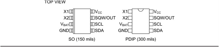
FIGURE 4-3 Pin-outs for the DS1307 chip.
We mentioned earlier that the NXT does not charge a royalty fee for using the I2C protocol, but does charge a fee for registering an I2C device address. The DS1307 has been assigned the device address of 0×68, which identifies the chip whenever it and the Master need to communicate with each other.
Buried within the chip are a series of registers that maintain the data for the clock. The Timekeeper Registers are shown in Table 4-1. Note the register addresses and the function corresponding to that address. For example, register 0×05, is the register that holds the Month component of the date while register 0×00 holds the Seconds component of the time.
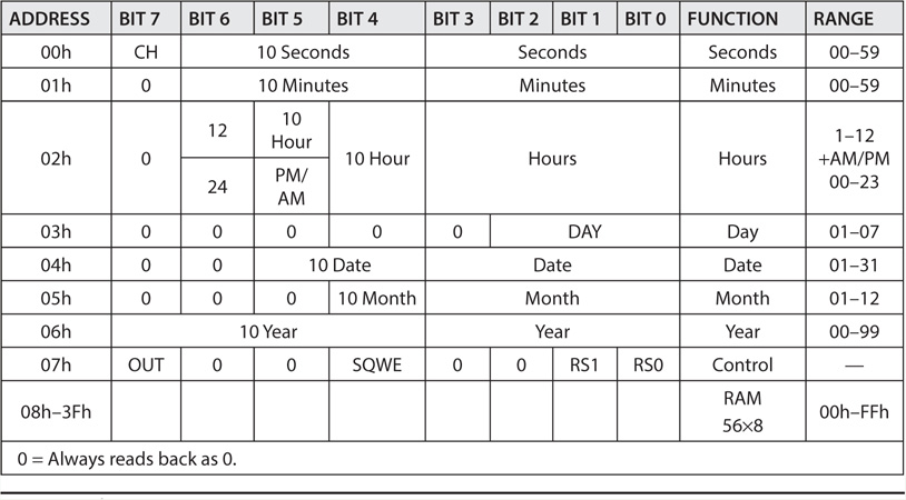
TABLE 4-1 The DS1307 Registers
BCD and the DS1307 Registers
In the DS1307, each register is an 8-bit entity, but values are stored in a format known as Binary Coded Decimal, or BCD. What this means is that each 8-bit register is treated as though it is partitioned into two smaller 4-bit registers. Such 4-bit entities are referred to as nibble ( … honest!) Now look at the Seconds register at address 0×00 in Table 4-1. The low nibble encompasses bits 0-3. Because any computer register ultimately stores its data in binary, the largest number that nibble can store is 1111 in binary, or 15 in decimal. However, since the Seconds register must be capable of storing values up to 60, it uses bits 4-6 to store the “tens of seconds.” For example, if you wanted to store 29 seconds in the Seconds register, the “low” nibble (i.e., bits 0-3) would contain the “units of seconds,” or 9 while the high nibble (i.e., bits 4-6, and ignoring the 7th bit) would contain the “tens of seconds,” or 2. Therefore, the BCD value in the 0×00 Seconds register would be 0010 1001. Think about it.
Table 4-2 should help you see how the BCD values are determined. Just remember that each binary digit, or bit, is a power of 2. Because each nibble is treated as an individual unit, the binary powers for the High Nibble are the same as those for the Low Nibble. That is, the power multipliers for each nibble are the same (i.e., the range of powers is 1 through 8 for each nibble). Therefore, in Table 4-2, there are 2 “10 Seconds,” or 20 in the High Nibble. (This is why Table 4-1 refers to bits 4-6 as “10 Seconds.”) In the Low Nibble, you find 8 + 1 = 9 “Seconds.” Because BCD treats each byte as a unit, you can see that the byte 00101001 in BCD translates to 29 seconds as a BCD value.

TABLE 4-2 BCD Conversion to Binary
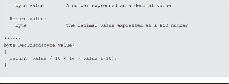
So, why do you need to know all of this BCD stuff? The reason is because the DS1307 registers are fluent in BCD and as dumb as a box of rocks in anything else. Therefore, to make the DS1307 do anything useful for us, we need to send and receive the register data in BCD format. The good news is that writing functions to convert BCD data the registers like to decimal numbers you and I understand is pretty trivial.
One more detail that should help you understand what’s going on inside the DS1307 when data are being placed on the I2C bus. The DS1307 maintains an internal register pointer that is automatically incremented each time a byte to read into or out of the chip. Therefore, unless you tell it otherwise, the DS1307 is going to store the first data byte it receives in the Seconds register (address 0×00); the internal register pointer is then incremented so the second byte goes into the Hours register. This sequential process continues until all data bytes have been transferred. This is why the read()s and write()s to the DS1307 are in the order that you see in Listing 4-3. Using some other order would mess up the data. Fortunately, the libraries that we use take care of most of the details for us. If you’re interested, you can examine each of the .cpp files for the libraries to figure out how they talk to the DS1307 across the I2C bus.
Constructing the RTC/Timer Shield
The completed RTC/Timer shield is shown in Figure 4-4. It is constructed on the LCD shield built in Chapter 3 using removable headers to mount the display to the shield.
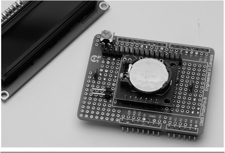
FIGURE 4-4 The completed real time clock/station timer shield.
To construct the RTC/Timer, you can use some of the empty nano-acres of real estate on the LCD shield you built in Chapter 3. We added a RTC module with its associated circuitry and a switch to reset the timer. The circuit for the RTC/Timer shield is shown on Figure 4-5. For the sake of clarity the circuitry associated with the LCD shield is not shown. Adding circuitry to the LCD shield is one reason we discussed using a removable header for the LCD display unit. We can unplug the display and add the circuitry underneath. Alternatively, the RTC/Timer can be built on its own shield using stackable headers to plug in the LCD shield.
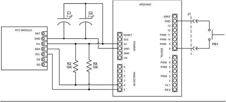
FIGURE 4-5 Real time clock/timer schematic diagram.
The RTC module is connected to the shield using a seven-pin header. The stubby ends of the header pins are soldered to the shield. The module should be mounted with the LiOn battery facing up. Should the battery need to be replaced at some future time, mounting the RTC module with the battery facing up makes it a lot easier to access the battery. Do not solder the module to the shield just yet, we first need to install some parts underneath the module. The module that we chose, shown in Figure 4-6, has components mounted on both sides. In particular, there is a quartz crystal (it is the small, shiny, tube-like object with two wires mounted on the side opposite the battery) that must be insulated to prevent shorting out the wiring pads on the shield. We used a small piece of heat-shrink tubing around the crystal, but other insulating materials such as electrical tape would work equally well.
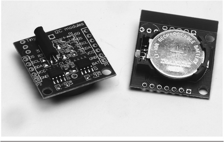
FIGURE 4-6 Real time clock breakout module (front and rear).
A WORD OF CAUTION: We have learned that some of the RTC breakout modules being sold on eBay are being supplied with a nonrechargeable Li-ion battery, a CR2032. The CR2032 battery can be problematic as some RTC breakout modules are designed to recharge the battery. The RTC breakout modules we are using include a rechargeable Li-ion battery, an LIR2032. The LIR2032 should not cause any problems but make sure that it is fully charged, the DS1307 RTC chip may not function with the battery partially discharged.
Looking at Figure 4-7, you can see how the parts are placed on the shield for assembly. The two 10 kΩ ¼ W resistors (R3 and R4) must be installed before the RTC module can be soldered down. Figure 4-8 shows the placement of the LCD shield with the RTC parts. The two 0.1 μF capacitors (C1 and C2) are added to help control noise on the 5 VDC circuit. This is common practice as noise on the power bus can induce errors if it’s severe enough. An ounce of prevention is worth a pound of cure, as they say.
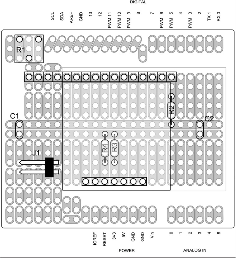
FIGURE 4-7 RTC/Timer shield parts placement.
You can mount the timer reset switch, SW1, directly on the shield, but we chose to have it detached so that the entire unit can be mounted in a project box. The switch, PB1, is wired through a plug into J1. Any normally open (NO) pushbutton switch may be used for PB1.
The RTC/Timer circuitry is wired up using our usual 24AWG solid wire using Teflon tubing added to insulate the wire. Figure 4-8 is a view of the wiring side of the shield. This should make it easier to wire the shield if you are not comfortable yet with schematics. The completed shield is shown in Figure 4-9 with the LCD removed.
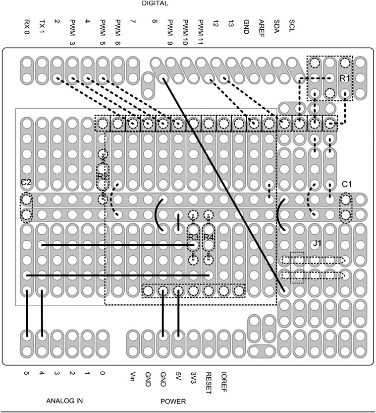
FIGURE 4-8 RTC/Timer wiring diagram (with LCD).
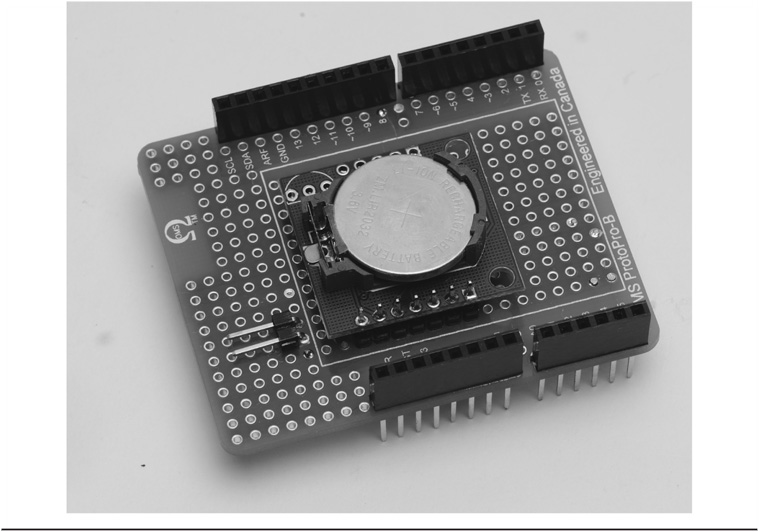
FIGURE 4-9 The RTC/Timer shield using the LCD shield.
An alternate version using a separate LCD shield is shown in Figure 4-9. The alternate design uses the LCD shield that we constructed in Chapter 3. Instead of using regular header pins to attach the RTC/Timer shield to the Arduino, we use stackable headers (see Figure 3-8 for reference). As the LCD is not integrally a part of the RTC/Timer shield, we can eliminate a lot of the wiring shown in Figure 4-8. The wires not needed are shown as dashed lines in the wiring diagram, Figure 4-8. Figure 4-9 shows the completed shield with the LCD shield removed and Figure 4-10 shows the wiring side (i.e., Figure 4-8).
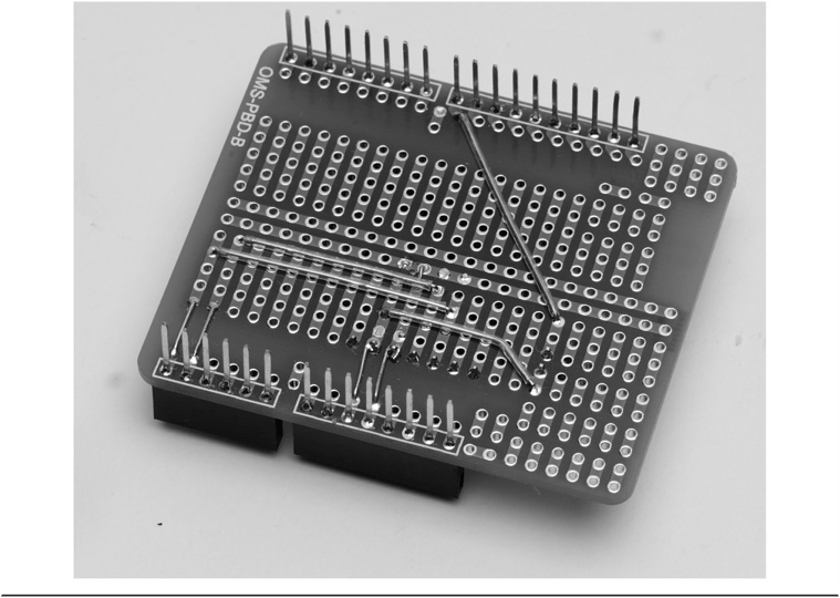
FIGURE 4-10 The wiring side of the RTC/Timer shield using the LCD shield.
The Adafruit RTClib Library
The software we wrote for the RTC uses two additional libraries that we have not used before. The first is the Wire library, which is distributed with the Arduino IDE. The Wire library contains the functions we need to use the I2C bus. The second is the Adafruit RTClib library, which is a free download at:
https://github.com/adafruit/RTClib
This library greatly simplifies the initialization of the RTC at start-up, as you can see in Listing 4-3.
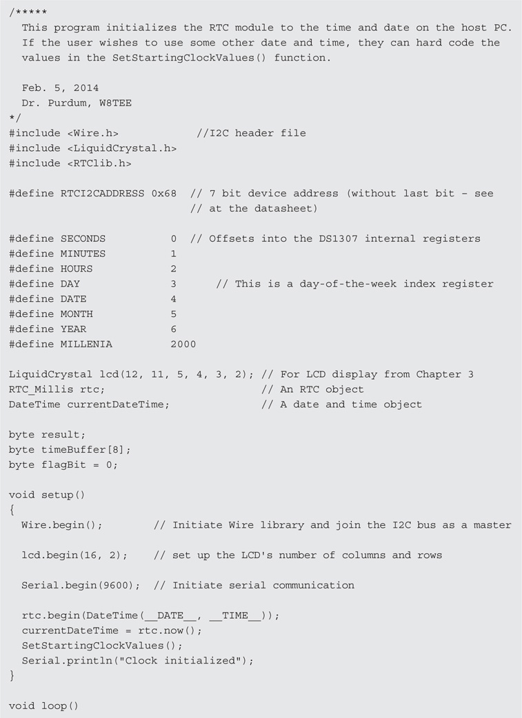

LISTING 4-3 Initialization of DS1307 date and time data.
Initializing the RTC
If your RTC doesn’t come with a battery already in place, or if you need to replace it, you need a way to initialize the registers in the DS1307 chip so they contain valid data. You can do this “by hand,” wherein you write specific values into the registers. The program in Listing 4-3 provides a simple way to either use specific data you wish to use or simply copy the date and time data from your PC. We assume that copying the host PC’s date and time data is good enough.
The program begins by initializing the I2C interface via the Wire library, which is part of the libraries supplied with the Arduino IDE. The code also creates objects for the RTC, the LCD display, and a communication object (Serial). Having done that, the program performs a DateTime() call to the host PC to retrieve its current date and time data, using that data to initialize the RTC object (rtc). The rtc object calls the now() method to break out that data into currentDateTime. The function SetStartingClockValues() simply copies the DateTime object’s information into the DS1307 registers. The nested calls to the DecToBcd() function converts the decimal data stored in into the BCD values the DS1307 wants. The program then displays a message informing you that the RTC is now initialized.
The software presented in Listing 4-4 is designed to be used in conjunction with the shield schematic depicted in Figure 4-5. We should point out that for the first RTC shield we built, Jack installed the RTC clock module you see in the middle of Figure 4-11 with the battery under the RTC module. While this approach makes it easier to see what the pins on the module are, changing the battery is going to be a problem. This is why the construction details for the RTC installed the RTC module with the battery side up. However, given the projected battery life associated with the DS1307 and using a CR2032 button cell, we have about 10 years before we need to think about changing the battery for the shield Jack built upside down.
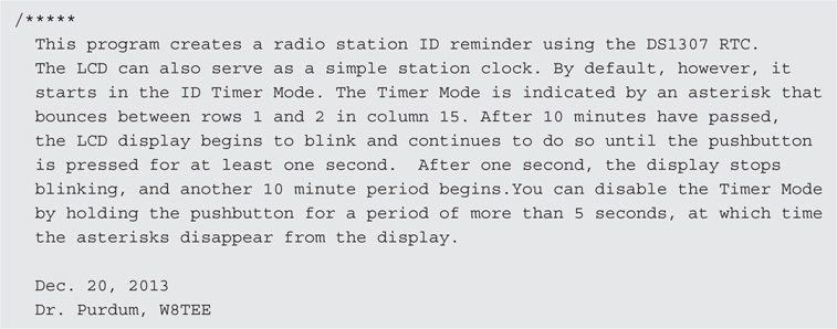


LISTING 4-4 The RTC program.
Running the Program
When the timer is first turned on, the display shows the current time and causes a counter (millisStart) to record the current number of milliseconds as stored in the Arduino via a function call to millis() in the setup() function. On each pass through loop(), the current millisecond value is read via another call to millis() and that value is stored in millisCurrent. When the difference between millisStart and millisCurrent is 10 minutes (IDTIMESLICE, or 600,000 milliseconds), the code blinks the LCD display. The LCD display continues to blink until the user presses the pushbutton (PB1). Once the user presses the pushbutton, millisStart is reset and the 10-minute timer period starts again. We call this mode the Timer Mode.
If PB1 is pushed, but held for more than MODESWITCHDELAY seconds, the RTC clock toggles to its alternative state. For example, if the clock is in Timer Mode and the user pressed PB1 for more that MODESWITCHDELAY seconds, the clock switches to Clock Mode. We chose to call it Clock Mode because … wait for it … in Clock Mode, the RTC clock acts as a standard clock. This means the RTC is not acting as a timer. You can tell which mode is active by the presence (Timer Mode) or absence (Clock Mode) of asterisks in column 15 of the LCD display. In Timer Mode, the asterisks bounce between rows 1 and 2 on the display (see Figure 4-1). In Clock Mode, no asterisks are present.
The LCD shield you built in Chapter 3 stacks on top of the RTC shield shown in Figure 4-11. (See Figure 4-12.) The “Arduino sandwich” shown in Figure 4-12 is not uncommon in Arduino projects. Indeed, being able to stack shields is one of the real strengths of the Arduino design, as it adds a tremendous amount of flexibility to the functionality of the Arduino.
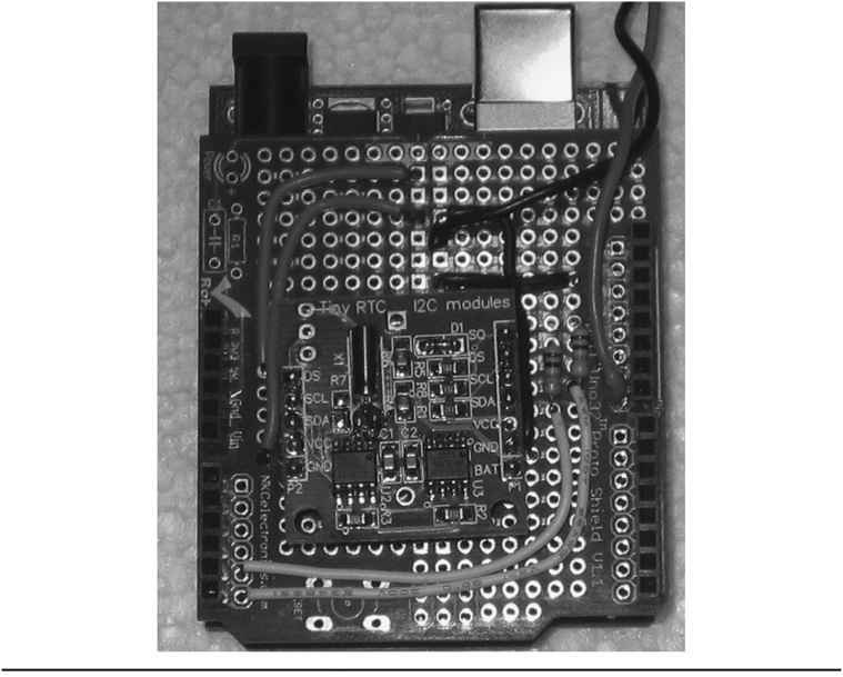
FIGURE 4-11 Jack’s initial RTC shield with hidden battery.
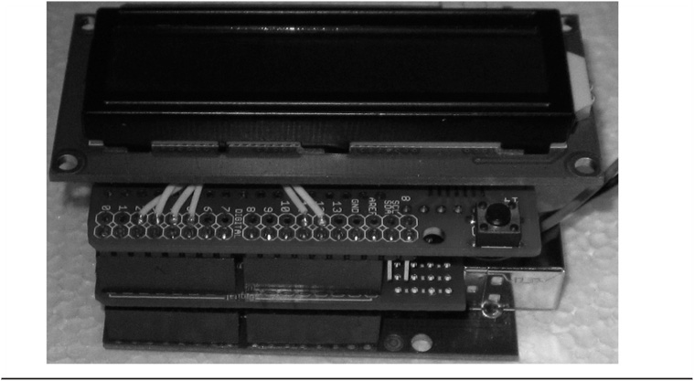
FIGURE 4-12 The Arduino on the bottom, the RTC in the middle, and the LCD shield on top.
The RTC Timer Program
There’s not too much new in the code presented in Listing 4-4. Note that the program does assume that you downloaded and installed the RTClib library mentioned earlier in the chapter. The code defines several global variables from the libraries, including lcd for the LCD display and rtc for the RTClib library.
The beginTransmission() method puts the RTC device address (i.e., RTCI2CADDRESS or 0×68) on the I2C bus and writes a 0 on the bus to wake up the RTC module and tell it that some data for it are coming across the bus and reset its internal register pointer. After the data have been sent, the endTransmission() method of the Wire object tells the DS1307 that is has all of the data. If everything went correctly, endTransmission() sends the value 0 back from the call. As mentioned earlier, the sequence of the Wire.read() and Wire.write() method calls is important because of the way the DS1307’s internal register pointer works. If you observe screwy data coming back from the clock module, this is probably the first thing you should check.
The loop() Function
The loop() function is designed to simply update the clock on each pass through the loop. It begins with a call to millis() and assigns the data returned into millisCurrent. If the RTC is in Timer Mode, we check to see if the 10-minute time slice has been exceeded. We can do this because millisStart was set in setup(), so the difference between millisCurrent and millisStart is the elapsed time since the clock started timing, in milliseconds. If the 10 minutes has expired, we flash the LCD display and call the DisplayDateAndTime() function to update the display.
Next, the code checks to see if the user pressed the pushbutton switch, PB1. As mentioned earlier, PB1 has two functions: 1) to reset the timing period when in Timer Mode, or 2) to switch between modes. The length of the press on PB1 determines which action is taken. If the user holds PB1 longer than MODESWITCHDELAY seconds, featureChanged is set to true. Subsequent code uses the state of featureChanged to determine what to do next. By using the states of featureChanged and activeTimer, the code toggles the program into the desired mode.
Once the state of the program is known, a call to Wire.beginTransmission(RTCI2CADDRESS) is used to reset the internal register pointer of the DS1307 chip. The DS1307 maintains the current state of this pointer internally and if you don’t reset it yourself, it simply increments the pointer and reads whatever it happens to be pointing to. The register pointer is smart enough to “roll over” if your Wire.read() calls cause the pointer to point past the timer registers. Clearly, forgetting to reset the register pointer can cause the data returned from the Wire.read() calls to be out of sync with what you are expecting.
The call to Wire.requestFrom() is used to place the device address on the I2C bus and inform the device we want to retrieve 7 bytes of data from it. The method returns how many bytes are ready to be sent, which we assign into sentBack. If something went wrong, sentBack is set to 0 and our error function is called. Assuming no error occurred, sentBack should have the value of 7. We use that value to control a for loop to stuff the data from the RTC into the timeBuffer[] array. Again, the DS1307 only speaks BCD, so we must convert the data back to decimal before we place it in the timeBuffer[] array. This is why the Wire.read() calls are nested within the BcdToDec() function calls. The call to DisplayDateAndTime() simply moves the data from the timeBuffer[] array to the LCD display. After the data are displayed, the loop() method repeats the process again.
If 10 minutes passes without pressing the pushbutton, the LCD display starts blinking at a half second rate. The LCD display retains the time at which the display started blinking. A quick glance at your wristwatch and the LCD time will quickly tell you how long it’s been since you should have identified yourself. As a rough approximation, figure one month of jail time for every minute you’re late in identifying yourself.
You should pick an enclosure to house the cluster shown in Figure 4-12. Keep in mind that once you disconnect the USB cable, the display darkens, but the RTC clock keeps ticking by drawing power from the battery. Therefore, you should use a small power source (i.e., “wall wart”) that plugs directly into a wall socket and supplies between 7 VDC and 12 VDC. The Arduino’s onboard voltage regulator adjusts the incoming voltage to the requisite 5 V expected by the shields. Also, keep in mind that you need to mount the pushbutton in a way that makes it easily accessible for the user. You could add a power switch, but we just disconnect the wall wart when we don’t want the clock running.
A Software Hiccup
As stated earlier, we initialize the DS1307 registers with the date and time data from the host PC. (You can hard code the data, but that gets very tedious after recompiling the code several dozen times.) Obviously, initializing via the PC means we need to establish a Serial object in the code to handle the communications across the USB cable. When we uploaded the compiled code to the Arduino, the LCD display worked like a champ and displayed the proper time. No problem.
In theory, when we disconnect the Arduino from its power source (e.g., the USB cable), the onboard battery kicks in and maintains the RTC clock via battery power. So, we disconnected the USB cable and let the board sit for 30 minutes or so, then plugged a wall wart into the Arduino’s external power plug and observed the time on the LCD display. The time that was displayed was the time when we disconnected the USB cable from the Arduino, not the current time. Really? It appears that the DS1307 was storing the time and date data, probably somewhere in the 56 bytes of nonvolatile RAM that the chip has. This was puzzling.
We knew that the code should reinitialize the DS1307 each time we compiled and uploaded the code. However, the code should be set-it-once-and-forget-it … at least for 10 years or so. While debugging the code, we used the standard technique of toggling the debug code into and out of the program using the following type of preprocessor directive
which we used to encapsulate all of the Serial.print() calls, so commenting out the line:
#define DEBUG 1
at the top of the program and recompiling has the effect of removing all of our debug statements using the Serial object from the program.
Well … sort of.
As it turns out, we made yet another flat forehead mistake: We forgot to surround the:
Serial.begin(9600);
statement that is called in setup() with our #ifdef preprocessor directives. We are embarrassed to admit that we chased this “undocumented feature” of the program for over a day before we realized that the Serial.begin() method call causes the bootloader to perform a reset on the board. Evidently, the reset causes the DS1307 to cache the date/time data and shut down the chip’s internal counter. When power is reapplied, it restarts the internal counter, but using the values that were stored when the reset was sensed.
So what’s the solution? One solution is to simply compile and upload the code twice. The first time you maintain the link to the host PC with the Serial object so you can initialize the DS1307 registers with the current date and time. The second time, comment out the all of the code that uses the Serial object that fetches the date/time data from the PC or sends debug data to the host PC. Then simply recompile and upload the “No PC Talk” version of the code to the Arduino. Once we followed these procedures, the RTC performed as designed.
Instead of this compile-edit-compile process, we broke the initialization of the clock out into a separate program. This initialization program is the code presented in Listing 4-2. The code in Listing 4-4 is then used for the next 10 years.
Conclusion
In this chapter you have examined both a software and a hardware approach to creating a station ID timer. There are many areas where you can improve upon the design presented in this chapter. To avoid jail time, you could wire in a 200 W claxon (or perhaps a smaller buzzer) to sound instead of the blinking display. It’s easy to miss the blinking display: A 200 W horn … not so much. You could also try your hand at building an RTC module of your own from the chip. There are also a variety of ways that you can implement the Reset button once the 10-minute time period has passed. You might also want to blink the display at 9 minutes and 30 seconds to give the operator some time to end the current transmission. (Then fire off the claxon at 10 minutes because they ignored your warning.) To test your understanding of the DS1307 registers, try changing the software so the clock uses a 12-hour format rather than the 24-hour format we prefer. With a little imagination, there are a lot of modifications you might make to the hardware and software, if you are so inclined. If you do so, we hope you’ll post those on the book’s web site.
Have fun and experiment … it’s a great way to learn.