
CHAPTER 3
The LCD Shield Project
An important aspect of any μC system is the ability to display data in either text or numeric form. As you learned in Chapter 2, Step 4 (Output) of the Five Program Steps is designed to display the results of a program. One of the most common methods to display μC results is to output these data to a Liquid Crystal Display or “LCD.” LCDs are inexpensive and available in many configurations, from an array of dot-matrix characters to bit-mapped color displays with built-in touch screens. As our first construction project, we chose to assemble a 16 × 2 dot-matrix LCD display.
We chose the LCD display as a first project for several reasons. First, the construction and software for this project is simple and a good starting point for our discussion of amateur radio projects. Second, this display is used in several subsequent projects that only need one or two lines of text for display. Third, the overall size of the 16 × 2 LCD display is small, thus lending itself to small enclosures that are compatible with many QRP rigs. Finally, these displays are easy to find and fairly inexpensive, usually costing less than $5. You could modify the design presented in this chapter for a 20 × 4 display without too much difficulty, but the display would be somewhat larger and two or three times more expensive. The finished display shield is shown in Figure 3-1.
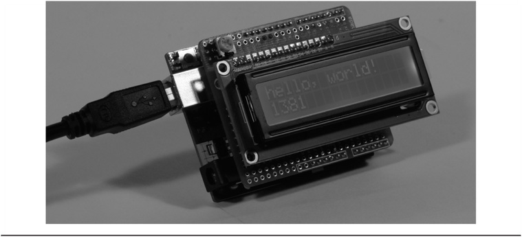
FIGURE 3-1 The completed LCD shield piggybacked onto an Arduino.
The Arduino development system is designed as a flexible prototyping environment. The Arduino board has a series of connectors around the edges that may be used to connect to “shields,” the term used in the Arduino community to describe “add-on” modules. If assembled properly, shields can be plugged into the Arduino and stacked one on top of the other, further enhancing the capabilities of the system.
Libraries: Lessening the Software Burden
The LCD shield is designed to use the standard Arduino software libraries that are distributed as part of the Arduino’s IDE installation. In Chapter 2 you learned that functions are the basic building blocks from which applications are created. You can think of a software library as a collection of functions designed for some specific purpose. In many ways, an Arduino library is much like a single book. The book has a title that reflects its general area of interest (e.g., LCD). Opening the book and inspecting its table of contents (TOC), you discover more details about the book’s general area of interest. Each chapter title in the book’s TOC provides more information about the general area of interest (e.g., setCursor(), write(), clear()). By reading each chapter, you learn how to use the LCD feature that is the subject of that particular chapter. Each chapter provides you with the details you need to know on how the functionality of that particular chapter is used within your own programs.
The Arduino environment provides you with dozens of libraries. Some are shipped with the IDE, others are available as free downloads from various web sites. Later chapters use some of these additional libraries. Whenever we use a “non-IDE” library, we tell you where you can find the library for download. It’s worth your time to read about the libraries that already are provided with the Arduino IDE (see http://arduino.cc/en/Reference/Libraries). Knowing what the libraries contain helps prevent you from reinventing the wheel. Also, any time you think you need to write your own library because you don’t think a library exists for that area of interest, do a Google search first. You’ll be surprised how often you’ll be able to stand on the shoulders of someone else who has already done most, if not all, of the work for you. That’s what Open Source is all about … sharing your work.
In this chapter, you use the LCD software library, named LiquidCrystal, that is distributed with the Arduino IDE. At the completion of this project, you will have learned how to assemble the shield, use the correct LCD library functions, and execute the “HelloWorld” example program sketch that is included with the LCD library. You will also learn how to use various library functions to display different data types. Virtually all of the software used in this project is already written for you.
Not All LCDs Are the Same
An important thing to note is that the LCD display libraries are written to use a specific LCD controller chip, the HD44780. Developed by Hitachi, the HD44780 controller greatly simplifies the hardware and software needed to use the LCD display. Make sure that the LCD you use employs the HD44780 controller or its equivalent. If you must use a different LCD controller, make sure the vendor supplies Arduino-compatible libraries with it. Most online vendors make a statement if their LCD is compatible with the HD44780 controller. If you don’t see such a statement in their ad, you should write and ask if their LCD is compatible with the HD44780 and, if not, do they supply Arduino-compatible libraries. While there is nothing to prevent you from writing your own library for a noncompatible display, clearly more time and effort on your part is required to do so. However, if you do write a new library, we encourage you to make it available to Open Source.
As pointed out earlier, we chose to use an LCD that has 2 rows of 16 characters (commonly referenced as a 2 × 16 LCD). The displays are available in other form factors; more rows, or more characters. It is perfectly fine to use one of these other displays but you will have to modify our program code to accommodate the different form factor. There are articles in the Arduino Forums that should help you to use these other LCD formats (see http://forum.arduino.cc/index.php?board=7.0).
Also be aware that some LCD displays do not have backlighting. Backlighting refers to the illumination that appears as a background for the LCD characters. Without backlighting, the display depends upon ambient lighting to provide enough contrast to read the display. While backlighting of the LCD display is not required, we think it is definitely worth having. Nonbacklit displays are a little cheaper, but not enough to make it worthwhile. We suggest you always purchase backlit displays.
LCD Shield Parts List
All of the parts needed to assemble the LCD shield are presented in Table 3-1.
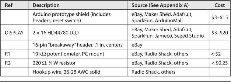
TABLE 3-1 LCD Shield List of Parts
Clockwise from the upper left in Figure 3-2, the parts are: R1, a 10 kΩ potentiometer, a prototyping shield to hold the parts, header pins for connecting the shield to the Arduino, the LCD display module, and the 16-pin header for connecting the LCD to the shield. Note that in the construction projects presented in this book, a potentiometer (or “pot”) is a small, printed circuit board (PCB) type you adjust with a screwdriver, not the larger type you find on audio equipment that you adjust with a knob. Also, there is considerable variance in the cost of parts because some suppliers, especially foreign suppliers like those often found on eBay, are extremely inexpensive. The downside is that you may have to wait a while longer to get your parts since they often come from China or Thailand. Because you probably will not want to stack another shield on top of the LCD display, we recommend using the “breakaway” headers to interconnect this shield to any shield that may be under it. You can see these headers near the top of Figure 3-2. However, you can optionally make the LCD removable using stackable headers.
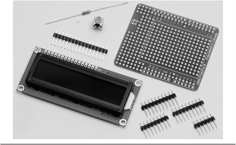
FIGURE 3-2 LCD shield parts.
Prototyping shields come in many forms as can be seen in Figure 3-3 and are available preassembled or as a kit. The kit gives you some flexibility in how the connectors are installed, either as a stacked shield (i.e., one built to connect directly to the Arduino board) or not. A prototype shield, or proto shield, has a number of isolated holes into which you can insert components. The holes are “plated-thru” and allow you to solder your components to the board. Plated-thru holes is a term that means that the holes that accept the components on the board are all lined with conducting material so the connections extend from the top of the board through to the other side of the board. Some boards may have holes that are interconnected with other holes, which can help simplify wiring. Some have pads for installing Dual In-line Package (DIP) or Surface Mount Devices (SMD) or other parts, while others duplicate the layout of a solderless prototyping board as described in Chapter 1. These solderless prototyping boards often have two “buses” (i.e., heavy lead traces) running down the center (perfect for V+ and ground) and columns of interconnected pins. If you look closely at Figure 3-3, you can see buses on the boards at the top-left and lower-right side of the figure.
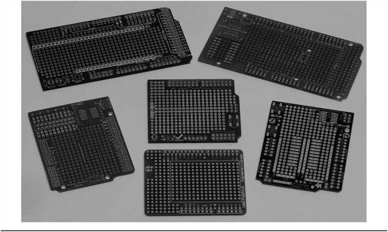
FIGURE 3-3 Examples of prototyping shields.
Selection of a prototyping shield depends on the nature of the project you want to build. For instance, how many parts are needed for the project? Will all of the parts fit on a single board? Do you need to mount any SMD parts? And let’s not forget personal preferences. We have an affinity toward using the shields that are similar to the solderless prototyping boards so our choice would be this style of proto shield in kit form. The shield we are using for this and many other projects in this book come from Omega MCU Systems in Canada (see http://oms.onebytecpu.com). We obtained the proto shield for this project from eBay as a bare board.
Assembling the LCD Shield
The LCD shield is shown as a schematic diagram in Figure 3-4. The schematic shows how the LCD shield parts are connected together.
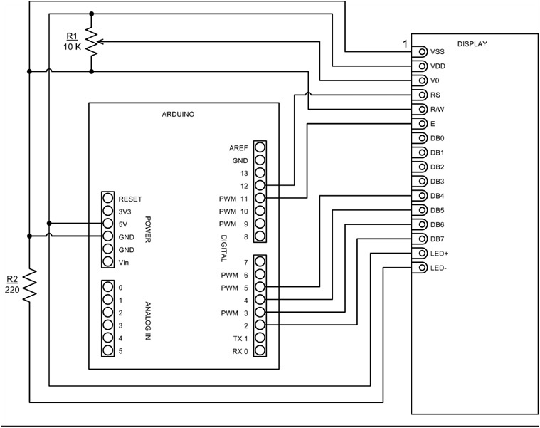
FIGURE 3-4 LCD shield schematic.
One thing we find very helpful in assembling a shield is a layout drawing. If you have access to some type of drawing package or even if you use a sheet of quad-ruled paper, laying the parts out ahead of time will save you time in the long run. Make sure that there are enough solder points for the LCD header and that the 10K pot can be installed so it doesn’t interfere with the display or is hidden behind it. There is nothing so painful as assembling a number of components on a prototyping shield and then realizing the last part won’t fit. Reworking the parts placement is time consuming, you risk damaging the shield and the components, and is generally zero fun. It is much better to take your time, sketch out a layout, and test-fit the components prior to ever applying the soldering iron. We have used Microsoft Visio to create the layout examples for this book. You can also do an Internet search for free schematic drawing downloads and find a number of free drawing tools, such as TinyCAD (http://sourceforge.net/projects/tinycad/).
Figure 3-5 shows an example of one way to lay out the LCD shield. We also use the layout to help with the wiring by transferring the interconnections from the schematic diagram as is shown in the layout drawing.

FIGURE 3-5 A layout drawing for the LCD shield.
To assemble the shield you first need a “bare” prototyping shield similar to that shown in Figure 3-2. An example of a bus mentioned earlier can be seen near the center of Figure 3-5. The buses make it easier to connect components that share a common connection (e.g., +5 V and GND). Once a part is inserted and soldered onto the board, do not immediately trim the leads as these leads provide a convenient place to make interconnections with other components. Trim the excess only after you have completed the last connection to that part.
Breakaway Header Pins
Now that you have all of the parts needed for the LCD shield and you have a rough layout, you can begin assembly. The first step is to prepare and install the breakaway headers. Figure 3-6 shows a standard 40-pin breakaway header. You can use a pair of diagonal cutters to cut the header to the desired length as shown in Figure 3-7. Figure 3-8 shows a comparison between stackable and standard headers and a socket. The stackable header (top right in Figure 3-8) not only provides connection to the Arduino or shield underneath, but also allows another shield to be inserted from the top. We make use of this feature in future projects, but for this project you might consider using the socket header (top left in Figure 3-8) for mounting the LCD. This allows easy access to the area under the LCD should you want to add some circuitry at a future time. It really beats trying to unsolder the LCD, which we find similar to putting toothpaste back into the tube.

FIGURE 3-6 Standard 40-pin breakaway header.

FIGURE 3-7 Using diagonal cutters to cut the breakaway header.

FIGURE 3-8 Comparison of stackable and standard headers and a header socket.
The first step in assembling the LCD shield is to solder the headers that connect the shield to the Arduino. Note that in Figure 3-6 the header pins have one side with a fairly long lead, while the other side of the plastic has a short, stubby lead. The best approach for soldering the headers to the shield is to insert the longer side of the header pins into your Arduino header sockets as shown in Figure 3-9.
FIGURE 3-9 Using Arduino to hold proto shield header pins.
Soldering Components to the Shield
Next, place the shield over the stubby pins and start soldering the stubby pins to the proto shield. This ensures that the header pins area aligned properly. If you are new to soldering, just follow these simple rules:
1. Apply the heat to the component being soldered, not the solder.
2. Apply the solder to the component being soldered, NOT the soldering iron.
3. Use just enough solder to flow around the component and wick into the hole.
4. Allow the parts to cool before moving them and especially before touching them.
Figure 3-10 shows what good and bad solder joints look like. A good solder joint is bright and shiny and fully “wets” the surfaces being soldered together, say, a pad on a prototype board and a component lead. A bad (cold) solder joint appears to have a grainy surface and looks more like the joint on the right in Figure 3-10. A bad solder joint doesn’t adhere to the component lead and the lead may in fact be loose.
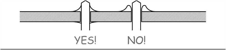
FIGURE 3-10 Comparison of good (left) and bad (right) solder joints.
Also, beware of solder “bridges.” As the name implies, a solder bridge is where two adjacent pins are connected by extra solder causing a short circuit, hence the term “bridge.” The bridges are created because of the surface tension of the liquid solder. The liquid solder tends to want to naturally create bridges! Solder bridges are sometimes hard to control but are easy to avoid and easy to clean up. Avoid bridges by only using enough solder to make the connection. Any extra invariably leads to trouble, like a solder bridge. If you should happen to create a solder bridge, clean it up using solder wick, a “solder sucker,” or even get the part hot with the iron and give the board a sharp “rap” on the work surface to remove the excess solder. Be careful with the latter technique as it doesn’t work well with delicate components and the excess solder always seems to seek bare skin. The latter has the same effect as catching a small meteorite with your bare hands … not good.
Figure 3-11 shows the proto board in place on top of the header pins, with the “stubby” ends of the pins protruding through the plated-thru holes. When you have soldered all of the stubby pins to the board, gently rock the shield slightly as you pull the proto board from the Arduino board below. When you have separated the two boards, you will see the longer ends of the header pins sticking out from the bottom of the proto shield.
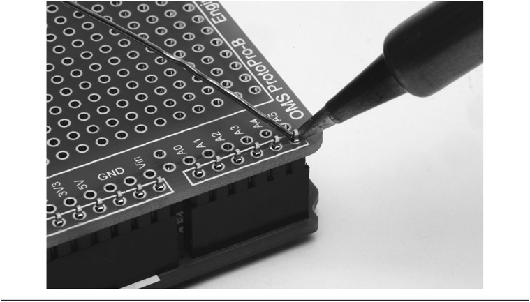
FIGURE 3-11 Soldering the stubby side of the header pins to the shield.
Figure 3-12 shows our parts placement for the LCD project. Compare Figure 3-12 with Figure 3-5 to see how the components are placed on the shield. It is best to add one part at a time to the shield, soldering as you go along.
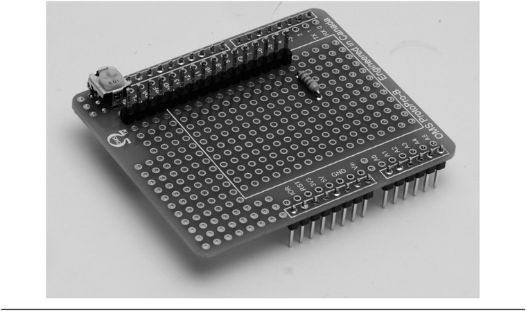
FIGURE 3-12 LCD header, potentiometer, and resistor placement.
Also note that in Figure 3-12 you can see the long pins “below” the board and the stubby ends of the pins are on “top” of the board. For this reason, we refer to the side with the stubby pins showing as the “top” of the proto shield, and the side with the long pins showing as the “bottom” side of the proto shield.
Insert the resistor in the appropriate location and solder it in place as shown in Figure 3-12 (and Figure 3-5), making sure that the body of the resistor is flush against the shield. You can use a pair of needle nose pliers to pull the component lead ever so slightly on the bottom side of the shield and gently bend it to one side (see Figure 3-13). This holds the resistor in place long enough to solder the leads. Once a part is inserted and soldered to the shield, do not trim the leads as we may use them in making interconnections to other parts. Trim the excess only after you have completed the last connection to that part. (If you are using a kit that came with a reset pushbutton this is a good time to insert and solder the pushbutton in place.) You can see in Figures 3-11 and 3-12 how the holes along the top edge where our header pins are installed are interconnected on this particular shield. We will make use of this to reduce the number of wires and complexity.

FIGURE 3-13 Soldering the resistor to the shield.
The next step is to solder the 16-pin header you just cut from the 40-pin strip to the shield. (You can see the placement of the 16-pin header near the top of Figure 3-12.) There is no “best way” to solder this header in place, but the method we use is to insert the stubby pins of the 16-pin header into the top side of the shield, flip the shield over to the bottom of the shield, and rest the shield on the workspace, letting the weight of the shield hold the 16-pin header in place. As shown in Figure 3-14, solder one stubby lead near the center of the strip (e.g., stubby lead number 7) and then lift the board to examine the header to see if it is perpendicular to the shield. If it is, solder the remaining stubby leads. If the shield is not perpendicular, then reheat the soldered pin while using a free finger to adjust the header by moving it with one of the end pins. This approach keeps you from burning your finger! Apply a little pressure on the end pin and heat the soldered pin while pushing the header into place. With the header properly aligned, you can solder the rest of the stubby leads. Eventually the LCD is installed on these pins, but don’t do that just yet. We’ll discuss mounting the LCD a little later on. We have some more work to do first.

FIGURE 3-14 Soldering the 16-pin header for the LCD.
Continue by inserting and soldering the potentiometer in place. Once again, you can use the technique of soldering one lead and pressing the part into place to get a flush fit. Once you are happy with how the potentiometer looks, solder the remaining two leads.
Adding Components Using a Schematic
Review the schematic in Figure 3-4 and familiarize yourself with the Arduino IO pins and the LCD. If you are new to wiring from a schematic, one helpful trick is to use a colored highlighter pen to mark the wires you have installed on the schematic. (Yellow is a good color choice for this. Black … not so much.) This helps to eliminate wiring errors. As mentioned earlier, showing the interconnections from the schematic on the layout drawing you have made is also very helpful. This prevents you from making other mistakes. Figure 3-15 shows the interconnecting wires to be added to the shield. Note that the wiring diagram is reversed from the parts placement diagram, Figure 3-5.

FIGURE 3-15 Diagram showing wiring on bottom side of shield.
Begin adding the connecting wires. Speaking of wires, the gauge of the wire you select can make things more or less difficult to fabricate. Clearly, the shield works with low voltage and amperage, so there’s no need for Romex cable. We prefer 24 AWG wire because it is easily bent for routing and quick to solder. Specifically, many of the shields shown in this book are wired with 24 AWG solid, bare wire and then covered with Teflon tubing of the appropriate size. With one end of the wire soldered in place, we cut the Teflon tubing to the needed length and slip it over the wire and then solder the remaining connection. This wiring technique makes for a clean, finished product as the Teflon tubing will not burn or melt when soldering the wire. Heavier gauge wire (e.g., 20 AWG) works fine, but is considerably thicker and more difficult to route. Another option is to use colored wires to denote different signals, for instance, red wire for the positive voltage lead and black wire for ground. Obviously, this is not a requirement, but it can make it easier to visually trace a circuit if something goes wrong.
There is no right way to wire a prototype board. Each builder adds their own individual touches. The sequence of photographs in Figures 3-16 through 3-19 shows one method for connecting a wire to an LCD header pin. Figure 3-16 shows a connection being made to the Arduino header for digital IO pin 4. The prototyping shield we are using here conveniently has holes connected to the adjacent header pins connecting to the Arduino. On the side of the shield away from the header we first solder a short piece of wire to the hole adjacent to Arduino IO pin 4. We then cut a piece of Teflon tubing to the proper length and slip it over the wire. The loose end of the wire is then wrapped around the LCD header pin using a pair of needle nose pliers and then clenched to hold it in place. Figure 3-17 shows solder being applied to the connection with Figure 3-18 showing the pin after soldering. Because no additional components are wired to this component, the excess wire is trimmed away as in Figure 3-19 and the connection is completed.

FIGURE 3-16 Detail of wrapping a wire around a header pin prior to soldering.
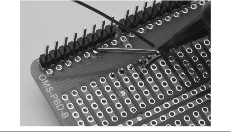
FIGURE 3-17 Soldering the wire …
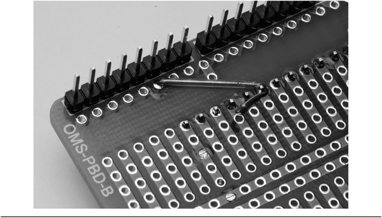
FIGURE 3-18 … Soldered …
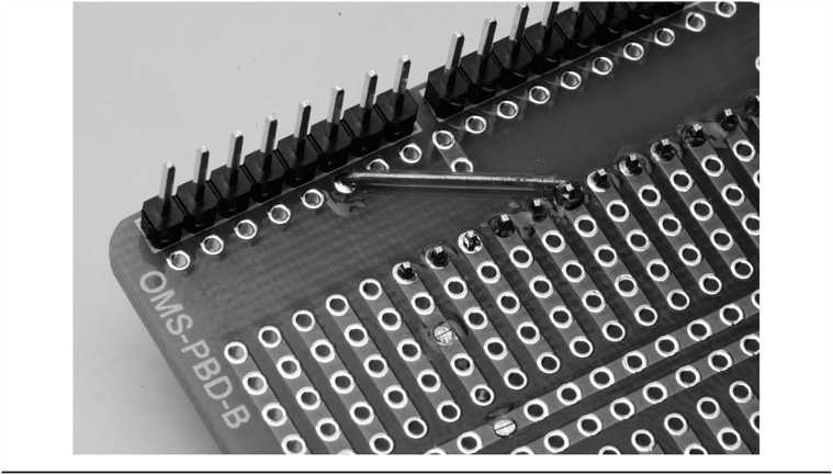
FIGURE 3-19 … And trimmed!
The process is repeated for the remaining connections. Each subsequent wire is cut to the proper length with Teflon tubing for insulation. We do this so as not to cause a short to the holes the wire may cross over. Once the wire is in place it can be soldered and trimmed flush on the other side of the shield.
Add the jumper wires to the bottom of the board as shown in Figure 3-15. Note that two adjacent holes connect with a bare jumper but for any other connection we use an insulated wire. Many times we can use the component leads (resistors, capacitors, etc.) to make the interconnections. Note how the jumpers take advantage of the existing circuits etched on the shield. When completed, the shield should look something like what is shown in Figure 3-20.
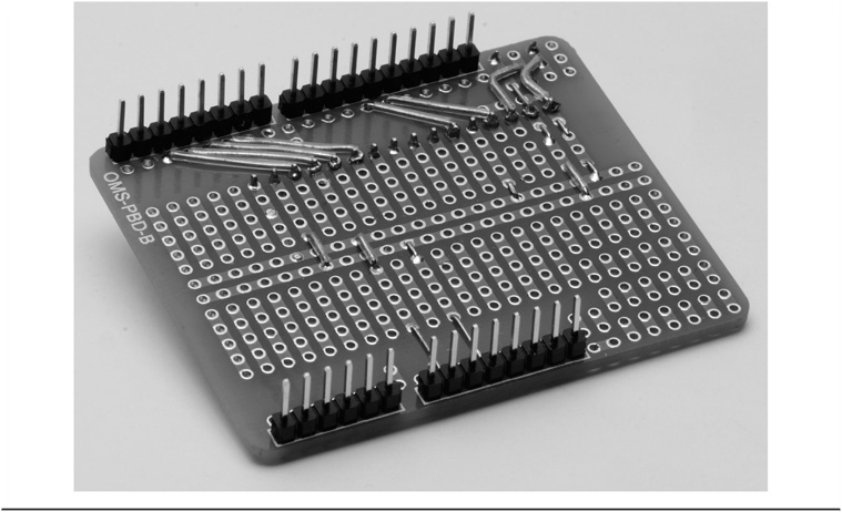
FIGURE 3-20 Completed wiring for the potentiometer, jumpers, and LCD header.
Once you have completed the wiring and before installing the LCD it is a good idea to check your work. A continuity tester is useful in this task. You can purchase a cheap multimeter for less than $10 and use it to check the resistance measurements for shorts. But lacking that, a visual inspection is sufficient. Since both of us are two years younger than dirt, we find a magnifying glass useful when checking for solder bridges. Check against the schematic diagram to see that each wire is connected to the correct points on the shield.
When you are confident that the shield is correctly wired, install the LCD. You should have decided by this point whether to permanently install the LCD or use header socket to make the display removable. If you are making it permanent, then set the LCD over the header pins and support it so that it doesn’t touch the shield itself. You can use a spacer between the LCD and the shield such as a piece of cardboard. Go back to Figure 3-1 to get an idea of what this should look like. Hold the display in place on the pins and solder just one of the pins somewhere near the middle. Now you can adjust the display to make it level and even on all of the pins, just as you did when first installing the headers on the shield. Once you are satisfied with the display’s position, solder the remaining pins. Again, watch for solder bridges shorting adjacent pins. Figure 3-21 shows the header pins being soldered to the LCD. Figure 3-22 shows how the LCD should look after being soldered in place.
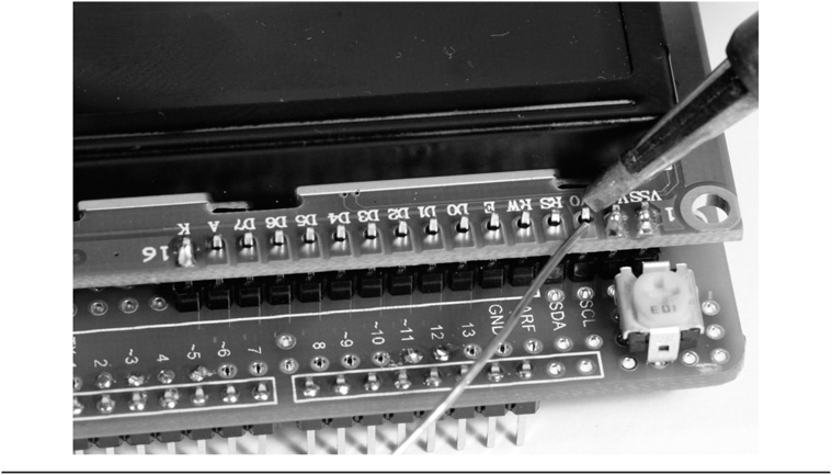
FIGURE 3-21 Soldering the LCD display into place.
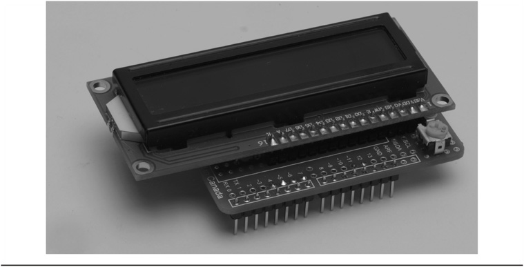
FIGURE 3-22 LCD mounting completed.
If you decided to make the LCD display removable, then you can use the same technique we used for installing the LCD header to the shield. Rather than a header, we use a header socket, as shown in Figure 3-8, to slip the LCD over the header installed on the shield. Insert the header socket pins from the back side of the LCD and solder one pin toward the center, align the LCD, and then solder the remaining pins, as shown in Figure 3-23. The completed shield with removable LCD is shown in Figure 3-24.

FIGURE 3-23 Soldering a header socket to the LCD.
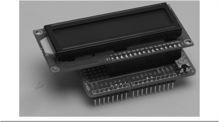
FIGURE 3-24 Completed LCD shield with removable LCD.
As a final touch after assembly, it is a good idea to remove the solder flux from your project. The flux residue is mildly sticky and will attract dirt and contaminants. It also detracts from the appearance of the finished project and that may be the greater reason. The easiest way to remove the flux residue is using laboratory-grade Isopropanol, or anhydrous isopropyl alcohol. This is not the stuff you get at the local pharmacy, “rubbing alcohol,” which is mostly water. Anhydrous isopropyl alcohol has very little water content and is ideal for removing flux. Apply the alcohol with a stiff brush, such as an “acid brush,” wiping the flux downward into a rag. Be generous with the alcohol. This type of alcohol, as well as the brushes, can generally be found at a good paint or hardware store. You will be pleased with the results.
An Alternative Design
As we mentioned earlier, there is no one “right way” to assemble the projects in this book. We provide examples of ways that they can be assembled. Here we show an alternative method using a different prototyping shield. We won’t go into the details of the construction, but the photographs in Figures 3-25–3-27 show different views of the alternative construction. In this example, the shield is constructed in such a way that it provides very few “built-in” wiring traces. As a result, all of the circuitry is added with individual wires. You can see them on the side view as they connect the LCD header to the Arduino digital IO header.
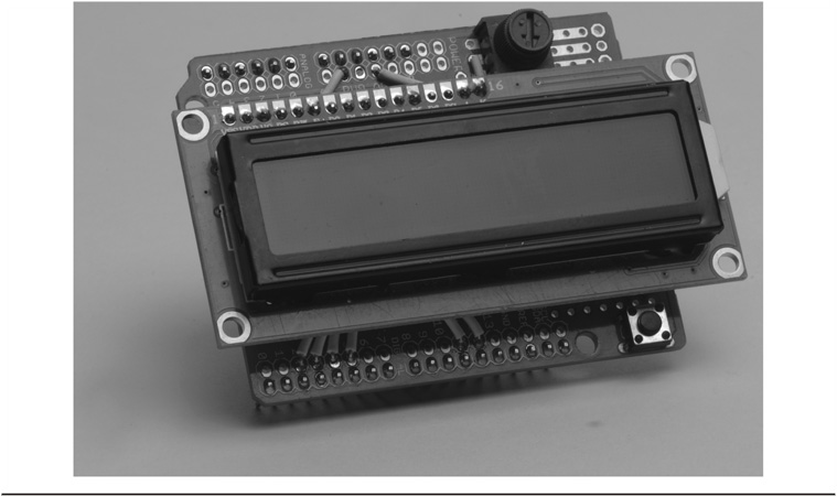
FIGURE 3-25 An alternative version of the LCD shield.
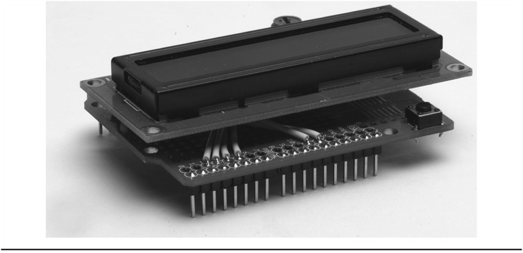
FIGURE 3-26 Side view of the alternative design.

FIGURE 3-27 Bottom view of the alternative design.
Loading the Example Software and Testing
All that remains is to load a test program and see that your work has been successful. You may need to adjust the 10K pot to get the correct contrast on the screen. The actual setting varies depending on the individual LCD, ambient lighting, and other factors.
Make sure your PC is connected to the Arduino board using a USB cable as discussed in Chapter 1. Now plug the LCD shield into the sockets on the Arduino board. You should see a series of “blocks” across the top row of the display. If not, adjust the LCD potentiometer until you see the blocks. The actual setting will vary depending on the individual LCD, ambient lighting, and other factors. Figure 3-28 shows what the display should look like when the contrast is correctly adjusted.
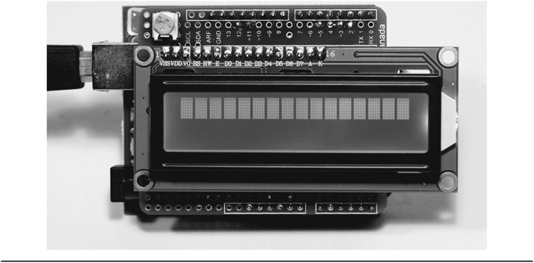
FIGURE 3-28 Adjusting the display for proper contrast.
Software to test the display is included with the Arduino IDE. Start the Arduino IDE and use the File → Examples → LiquidCrystal → HelloWorld menu sequence to locate “LiquidCrystal” and select the entry “HelloWorld.” This loads the program shown in Listing 3-1 into the Arduino IDE.
The HelloWorld program distributed with the Arduino IDE contains the following statement:
LiquidCrystal lcd(12, 11, 5, 4, 3, 2);
The numbers in the statement are pin assignments and are quite arbitrary. While we might prefer different pin assignments, we are sticking with the same pin assignments provided in the distribution software. However, some pins have special purposes. For example, pins 2 and 3 can be used to service external interrupts in addition to normal digital IO functions. Pin 5 can be used as an internal counter/timer. When conflicts arise, as might be the case for a program requiring an external interrupt, pin assignments may need to be changed. The software must reflect those changes.
Once you see the source code for the program appear in the IDE source code window, edit the lcd definition statement, then click the check mark icon (just below the File menu option) to compile the program. Fairly quickly a message appears on your PC near the bottom of the screen telling you the compile process is complete. The message also tells you the program’s size in bytes and the remaining unused program space. Now click the right-pointing arrow icon (below the Edit menu option) to copy the compiled program into the Arduino’s memory via the USB cable. (As an alternative, you can ignore clicking the check mark and directly click the right-pointing arrow. Doing so recompiles the source code and uploads the compiled program with a single click.)
After the upload completes, the IDE tells you the upload is complete and you can now see your handiwork come to life! Your results should look just like Figure 3-29. An explanation of the program follows source code Listing 3-1.

FIGURE 3-29 “Hello World!”
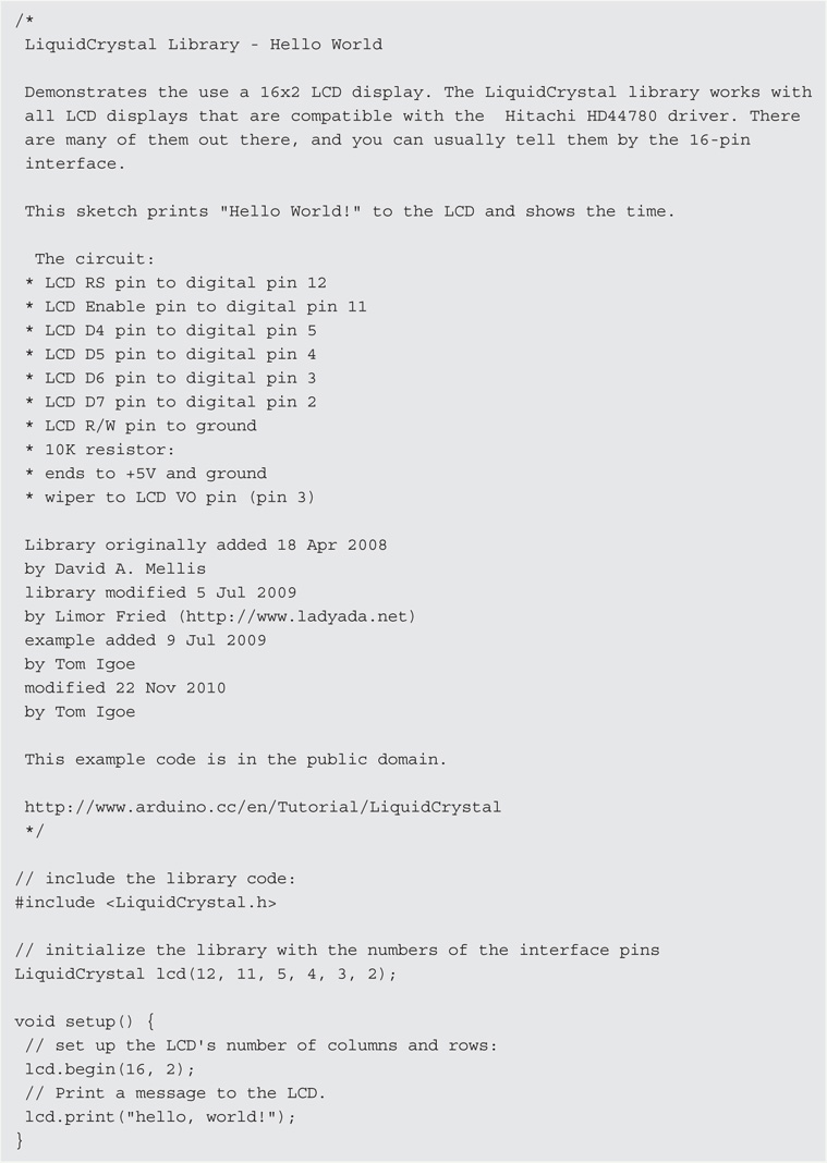
LISTING 3-1 The HelloWorld program.
A “Code Walk-Through” of the “HelloWorld” Sketch
Programmers use code walk-throughs as a more formal way to inspect the source code of a program. When Jack had his software company, he would assign clearly defined tasks to various programming teams. Most of these programming tasks had one- to two-week time frames, and all tasks were presented to all of the programmers on a Friday morning code walk-through, usually on staggered Fridays. The idea was for a different set of eyes to read and comment on the code. If the code “passed muster,” the company bought pizza for lunch and all of the programmers got the afternoon off. The code walk-throughs provided several benefits.
First, when you write code, often times you are “too close” to the code to see a bad design or a potential problem. It’s sort of like someone pointing out that your firstborn has a big nose; it’s the elephant in the room but you don’t see it. The code walk-through helps uncover potential problem areas before they actually become problems. Second, by making all programmers attend the meeting, you get a fresh perspective on the task at hand and the code designed to solve it. Often a non–team member came up with a design change that significantly improved the code. A third benefit is that everyone is at least somewhat familiar with what the other teams are doing. This was significant to Dr. Purdum’s company because it was always a small company and when someone took a week’s vacation and someone else had to fill in, at least those substitutes weren’t starting from ground zero. Finally, the code walk-throughs fostered an esprit-de-corps within the company because of the pizza-and-half-day-off carrot if the team succeeded. It reinforced the idea that one team’s success means everyone succeeds. You’d be amazed how often all of the programmers were at the office late Thursday night to help a team prepare for the code walk-through the next day even if it wasn’t their project that had the pending walk-through.
While you may not benefit in the same way from a code walk-through, we encourage you to read the discussion of the software issues even if you’re not interested in doing your own programming. If nothing else, it helps you understand what the software is doing and how it is done. Indeed, it may be that you can design a better hardware solution by understanding the software. Simply stated, the discussion of each project’s software element is like a code walk-through and helps you to better understand what the project is all about.
The HelloWorld program consists of several parts. As you already learned, the text between the first “/*” and “*/” is a multiline comment and everything between these two comment pairs is ignored by the compiler. In this particular example, these comments describe the circuit as you have built it and the names of the programmers who developed the LCD library. The symbol “//” is another comment, in this case a single line.
The #include in the line:
#include <iquidCrystal.h>
is called a preprocessor directive. Unlike C statements, preprocessor directives are not terminated with a semicolon. Only one preprocessor directive can appear on a line. The #include directive instructs the compiler to look in the appropriate library directory for the LiquidCrystal.h header file. If the line were written:
#include <LiquidCrystal.h>
(note the double quotation marks instead of the angle brackets), the compiler looks in the current working directory for the header file rather than the library directory.
The code found in the LiquidCrystal library contains a number of functions that can be called from the program, greatly simplifying the amount of code we have to write. Basically, the hard work has already been done for us.
The next statement:
LiquidCrystal lcd(12, 11, 5, 4, 3, 2);
is doing a lot of work for you using Object Oriented Programming (OOP) techniques. Think of the Arduino library as a room with a huge wall covered with hundreds of cookie cutters. One of those cookie cutters has the label LiquidCrystal etched on it. Another one has Stepper etched on it. Yet another has WiFi etched on its surface. Each cookie cutter represents a class that is available for you to use in your programs. You can think of a class as a container that holds information about some kind of object, an LCD in this example. When you write a statement that begins with a class name (LiquidCrystal) followed by a space, and then another variable name (lcd), you are actually calling a special C++ function called a class constructor whose job it is to carve out a chunk of memory according to the specifications of the class you are using.
In the statement above, you are taking the LiquidCrystal cookie cutter from the wall, pressing it into some cookie dough (actually, the dough is the Arduino memory), removing the new cookie (called an object of the class) and putting the label lcd on the object. The process of creating a class object is called instantiation. The numbers within the parentheses tell the class constructor how you want to initialize certain variables that are buried within the LiquidCrystal class definition. (The long comment at the top of Listing 3-1 gives you some insight as to the meaning of the numbers. We provide some additional information about these numbers in the next paragraph. We also discuss OOP techniques in greater detail in Chapter 7.)
During the process of executing the statement, you have used the LiquidCrystal class to create an instance, or object, of the LiquidCrystal class named lcd. If you had used the statement:
LiquidCrystal lcd();
to call the LiquidCrystal constructor, all of the members of the LiquidCrystal class would have been initialized with default values; zero for numeric variables and null (‘�’) for character arrays or other objects. However, since you chose to create the lcd object with six parameters, those values are stuffed into the appropriate member variables of the LiquidCrystal display object, lcd. If you look at the lengthy comment at the start of the program, you find:
which gives you a pretty good idea of what members of the Liquid Crystal display call mean.
You learned about void setup() in Chapter 2. The statement:
lcd.begin(16, 2);
actually goes to the lcd object you created in memory, and calls the begin() function that is defined within the LiquidCrystal class. Because the LiquidCrystal class can cope with several different display types, the parameters of our display (e.g., 16 characters in 2 rows) uses the begin() class method call to pass our display’s information to the class. (If you listen to a conversation among a cadre of OOP programmers, you will likely hear them refer to class methods. Methods are almost the same as functions, but they are buried within the class object. We may use the terms methods and functions interchangeably throughout this text since they serve a similar purpose.)
And now to output some text. The print(value) function (or method) call sends whatever is stored in the variable named value to the display. In this case, a sequence of characters (also called a string) is displayed, starting at the default cursor position, row 0, column 0. This call:
lcd.print(“hello, world!”);
actually sends the text string to the display object. While a simplification, you can think of the statement as going to the lcd object in memory, then looking for the memory address of where the print() method is stored within the object, and then have program execution branch to that memory address and execute the code found there. Note that, as explained in Chapter 2, since this first set of instructions is part of setup(), it is only executed once at program start-up. The type of data held in value and sent to the display can be either a text string or a numerical value. The double quotation marks (“”) symbols denote textual data. In the case of a numerical value, it can be the result of another call as in the second instruction below or just a numerical value.
The setCursor() function call allows you to specify where information is to be written to the LCD display. The instruction:
lcd.setCursor(0, 1);
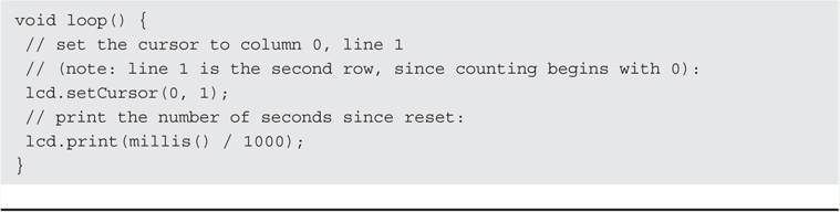
places the cursor at the first position in the second row. Remember that row–column coordinates are zero-based values, so the setCursor() function call above sets the column at position 0 and row 1 is actually the first column in the second row of the display.
lcd.print(millis() / 1000);
The lcd,print() function call displays an incrementing value at that position. The value is incremented once per second.
It is important to note that the function calls:
lcd.print(“hello, world!”);
lcd.setCursor(0, 1);
lcd.print(millis()/1000);
are using functions (methods) that are buried inside the lcd object. In other programs, you might see something like:
Serial.print(“hello world:”);
In this case, the statement is using the print() method that is buried inside the Serial class object. The two print() methods are quite different. Indeed, they have to be because our lcd object must configure the data for display on the LCD, while the Serial.print() method must configure the data to first travel over the USB connection and then display the data on your PC’s monitor.
Just keep in mind that the period, called the dot operator in C++, you see between the object name and the member name or the function name serves the purpose of an “information booth” for the object. For example, you can think of the statement:
lcd.setCursor(0,1);
as telling the program: “Go to the lcd chunk of memory and find its information booth. When you get there ask the person in the information booth for the memory address for the setCursor() method. Once you get to the memory address the information booth gave you, dump your data (e.g., ‘HelloWorld’) in their lap and they will take it from there.”
At this point it is worth the time to “play around” a little bit with the LCD and the associated software. Take some time to explore the Web link given in the listing:
http://www.arduino.cc/en/Tutorial/LiquidCrystal
This reference contains detailed explanations of the methods described above as well as the other methods that have not been used yet, but are part of the LiquidCrystal library. Now that you have a piece of hardware that you built yourself up and running, try making modifications to the example program source code in Listing 3-1. For instance, try placing the text in a different position or even output a second line of text rather than the counter. Performing little experiments like this helps make you more comfortable with making changes to the existing code.
Explore the Other Examples
You probably noticed a number of other example programs within the LiquidCrystal library. Take the time to load these and run them. Again, you can experiment with the examples and see how changing various values or parameters change things. If the code doesn’t run the first time, try to figure out why. (Did you remember to adjust the pin assignments for your display?) We use some of these additional lcd library methods in subsequent projects.
Congratulations! You have successfully completed your first Arduino shield and should now have a working LCD shield! In addition, you learned about the LiquidCrystal library function calls and how they work.
Using Your LCD Display with the TEN-TEC Rebel
In this section we want to show you how easy it can be to interface your LCD display into an existing piece of equipment. The piece of equipment we chose is the Rebel from TEN-TEC. This QRP rig has a long list of nice features for a two-band transceiver. However, the thing we really like is that it is Open Source software that helps make things tick inside of it. The beauty of this approach is that, if TEN-TEC or someone else comes out with a nice feature, you don’t have to shoe-horn a new board inside the rig. You just change the software. That’s what we do in this section: We change the software inside the Rebel so it can use your new LCD display.
The first step is to download the software you’ll need to modify the Rebel code. The Rebel source code can be downloaded from:
The name of the file is Rebel_506_Alpha_Rev02.pde. This is the origin source code from TEN-TEC. Note that you should keep a copy of this code in its original form in case you want to reload it at some time in the future. Obviously, TEN-TEC isn’t going to be responsible for what you do once you overwrite their software. After you download the source code and unzip it, you’ll notice that it is a *.pde file, not an Arduino-compatible *.ino file. The different file type segues us into the second step.
The second thing you need is the IDE for the chipKIT UNO32 μC that drives the Rebel. Strictly speaking, the chipKIT UNO32 is not a compatible Arduino μC. It is considerably more powerful and has features like 128K of Flash memory, 16K of SRAM, 42 I/O pins, and lopes along at a much faster 80 MHz clock speed. Despite those differences, we can make it talk to your LCD display. You can download the IDE at:
The Digilent IDE, called MPIDE, is available for Windows, Mac OS, and Linux. Make sure you put MPIDE in its own directory. Their IDE looks and feels like the Arduino IDE and you want to keep the two separate.
Under the Rebel Hood
TEN-TEC obviously made the Rebel to be “played” with, as you can see in Figure 3-30. They provide you with direct access to the μC via nicely labeled headers on the top of the main board. Notice that, unlike the Arduino shields, most of the headers are double rows. This is because of the higher number of I/O pins available on the UNO32. A USB connector exits the back of the transceiver and, just like an Arduino board, is where you connect the UNO32 to your PC for programming using a USB cable.
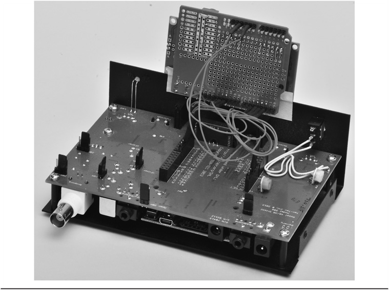
FIGURE 3-30 The rebel with cover off and LCD shield connected.
As you can see in Figure 3-30, we simply used jumper wires to connect the LCD display to the Rebel temporarily. A more permanent connection could be made using ribbon cable to connect the power and I/O lines from the Rebel to the LCD display. We bought an 18 in. old hard disk drive cable with 40 lines at a flea market for a dime. You could strip an 8 conductor section from that cable (i.e., 2 for power to the shield and 6 control lines) to make an inexpensive way to tie the rig and display together.
Software Modifications
Load the Rebel source code into the MPIDE just like you would an Arduino sketch. The name of the source code we had when this book was written was Rebel_506_Alpha_Rev02.pde. It’s quite likely that the name has changed in the intervening months. The line numbers we use in the following paragraphs, therefore, must be viewed as approximations because of changes TEN-TEC may make to later versions of the software.
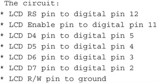
Now do a search (i.e., Ctrl-F) for “LCD.” You will likely end up somewhere around line 63 and see:

These comment lines provide details on the control and data pins the Rebel expects to be used for an LCD display. Jot these numbers down on a piece of paper or, if you’re young, memorize them.
Which Wires to Use to Connect Your LCD Display
Around line 247 you will find the following lines:
![]()
The lines of code above create a LiquidCrystal object named lcd for use by the Rebel. More importantly, what this tells you is how to connect your LCD display to the Rebel. In Listing 3-1 presented earlier in the chapter you can find the line:
LiquidCrystal lcd(12, 11, 5, 4, 3, 2);
which is the code that initializes your LCD display. From the two constructor calls that create the lcd object, for our display versus what the Rebel expects, we can construct a wiring table for your display, as seen in Table 3-2. The last two lines provide power from the Rebel to your LCD shield. You should make the connections shown in Table 3-2 to your LCD shield. No change to the code is required at this point. The software is still going to instantiate the lcd display object. However, since you are attaching jumpers from their pins to your display, the Rebel could care less who it is actually talking to and outputs the data to your new LCD display.
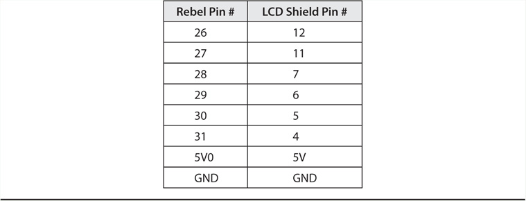
TABLE 3-2 Rebel-to-LCD Pin Connections
At approximately line 435 you will find the statement:
lcd.begin(16, 4);
which informs the Rebel that a 16 column by 4 row LCD has been connected to the Rebel. Well, that’s not true for our display, so you should change this line to:
lcd.begin(16, 2);
Your Own Splash Screen
If you would like to add your own custom “splash” screen, you can add lines similar to the following lines immediately after the lcd.begin(16, 2) call made in setup():

The code above displays a short splash message about the display. If your name isn’t Jane, edit that line and insert your own name (or whatever), but make sure it doesn’t contain more than 16 characters. If the line becomes much shorter than 16 characters, you can edit the lcd.setCursor(1, 1) line and center the text in the second display line if you wish using:
lcd.setCursor((16 – messageLength) / 2, 1);
where messageLength is the number of characters in your message.
Now find the loop() function in the source code. You should find loop() near line 503 in the file. Now add the new statement as indicated below to the file after the opening brace for loop():

The keyword static allows oldFrequency to retain its previous value on each pass through loop(), even though it is defined within loop(). A little farther down (e.g., line 515) you should see the statement:
frequency_tune = frequency + RitFreqOffset;
Add the following new lines immediately below the line above:
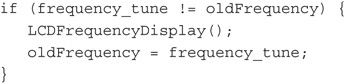
The new lines of code compare the old frequency to the current frequency. If they are not the same, the LCD display needs to be updated with the new frequency (i.e., the user is tuning across the band) via the LCDFrequencyDisplay() function call. We then update oldFrequency to the current frequency. On the other hand, if the two frequencies are the same, there is no reason to call the LCDFrequencyDisplay() function. If we called the display on every pass through the loop, we could introduce a little bit of flicker in the display.
The code for the LCDFrequencyDisplay() function appears in Listing 3-2.
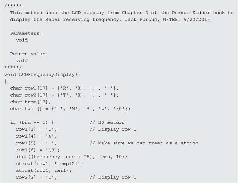
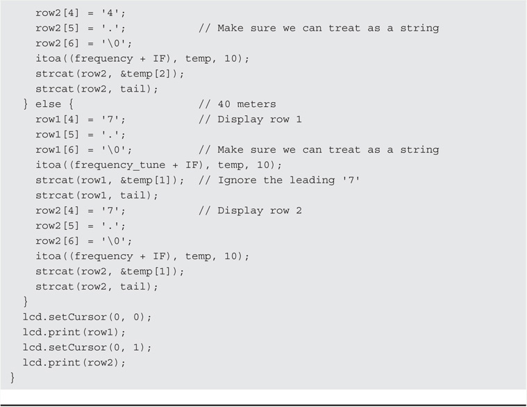
LISTING 3-2 Modified LCD display program.
We placed the new function in Listing 3-2 just before the loop() function (around line 500) and just after the definition of their Default_Settings() function. Simply stated, the code displays the transmit and receive information on the LCD display. Save your work with a name that is different from the original source code, perhaps something like RebelSourceWithLCDDisplay.pde. Now compile and upload the file just like you would an Arduino sketch.
Disconnect the USB cable and power up the Rebel. You should see your splash screen for a second and a half, and then the default start-up frequency for the Rebel. It should look similar to Figure 3-31. As you tune around the band, the display updates accordingly. If it doesn’t, you’re on your own.
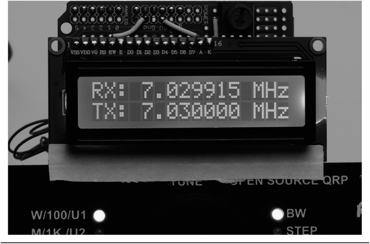
FIGURE 3-31 Rebel display.
Naw … just kidding. Simply reload the software into the IDE and go through the steps again. Make sure you are changing the code at the correct code sections as some of the #defines appear at multiple places in the code.
Other hams have made similar changes to their Rebel, and have routed a multiline cable from the Rebel to another case that houses the shield and display. This makes the display more permanent and professional looking. Still, having the case open with wires all over the place like you see in Figure 3-30 is kinda cool in a geeky sort of way. Your choice …
Conclusion
In this chapter you built an LCD shield that can be used for a variety of uses, some of which are detailed in later chapters. The construction techniques used to build the LCD display are used for building other shields in other projects. For now, we encourage you to experiment with the shield and perhaps try your hand at modifying the code presented in Listing 3-2. The changes don’t have to be earth-shaking, just something that makes a small difference in the way the program functions. You can always start over, so there’s no reason not to give it a try.