
CHAPTER 1
Introduction
Many, many, years ago, Jack was a member of the local Boy Scouts group in his home town. Jack’s scout leader had arranged for the troop to spend some time at the home of a local merchant named Chuck Ziegler who was a ham radio operator. As Jack recalls, Chuck had a schedule with his son every Sunday afternoon. What really impressed Jack was that Chuck was in Ohio and his son was in South Africa! In the weeks and months that followed, Jack spent many hours watching Chuck twiddle the dials on his all-Collins S-Line equipment feeding a 50-ft-high tri-band beam. It wasn’t too long after that initial meeting that Chuck administered Jack’s Novice license exam. Jack has been licensed ever since … almost 60 years now.
Our guess is that each ham has their own set of reasons about what attracted them to amateur radio in the first place. In our case, we both really enjoy the potential experimentation in electronics as well as the communications elements. Lately, we have also become more intrigued by emergency communication and QRP (i.e., low-power communications using less than 5 W of power). In essence, that’s the core of this book: making QRP communications even more enjoyable via microcontroller enhancements. While many of the projects are not actually “QRP only,” it is just that a lot of them are features we wish inexpensive transceivers had but usually don’t. Many other projects presented in this book are just plain useful around the shack.
Microcontrollers have been around since the early 1970s, but they have been slow to penetrate the amateur radio arena. However, a number of things are beginning to change all of that. First, the unit cost of many popular microcontroller chips is less than $10, putting them within the price range of experimenters. Second, several microcontrollers are Open Source, which means there is a large body of existing technical information and software available for them at little or no charge. Finally, despite their small size, today’s microcontrollers are extremely powerful and capable of a wide variety of tasks. Most development boards are not much bigger than a deck of cards.
Which Microcontroller to Use?
There is no “right” microcontroller for every potential use. Indeed, showing preference of one over another is sort of like telling new parents that their child has warts. Each family of microcontrollers (we’ll use μC as an abbreviation for “microcontroller” from now on) has a knot of followers who are more than willing to tell you all of the advantages their favorite μC has over all the rest. And, for the most part, they are telling you the truth. So, how do you select one over all the others?
The Arduino μC board began in 2005 by a group of students in Italy using an 8-bit Atmel AVR μC. The students’ goal was to develop a low-cost development board that they could afford. The original hardware was produced in Italy by Smart Projects. Subsequently, SparkFun Electronics, an American company, designed numerous Arduino-compatible boards. Atmel is an American-based company, founded in 1984, that designs and produces μCs which form the nucleus of the Arduino boards.
Figure 1-1 shows several Arduino-compatible μC boards. The chipKIT Uno32 shown in the upper right of the picture is actually not part of the Arduino family of boards, but it can run all of the programs presented in this book. It costs a little more, but has some impressive performance characteristics. It is also at the heart of a new Open Source Rebel transceiver from TEN-TEC.

FIGURE 1-1 Arduino-compatible microcontrollers.
Well, perhaps the more important question is why we bothered to pick one μC over another in the first place. Since many of them have similar price/performance characteristics, why make a choice at all? As it turns out, there may be some pretty good reasons to select one over another.
Part of the reason probably has to do with the Jack-of-All-Trades-Master-of-None thingie. While the size, cost, and performance characteristics of many μCs are similar, there are nuances of differences that only get resolved by gaining experience with one μC. Also, the entry price point is only the tip of the development cost iceberg. For example, how robust are the support libraries? Is there an active support group behind the μC? Is the μC second-sourced? How easy is it to get third-party support? Are there add-on boards, often called shields, available at reasonable cost? What’s the development language? No doubt we’ve left out a host of other important considerations you must make when selecting a μC for your next project.
Clearly, we ended up selecting the Arduino family of μCs. We did, however, consider several others before deciding on the Arduino family. Specifically, we looked long and hard at the Netduino, PIC, Raspberry Pi, and pcDuino μCs. The PIC family is actually similar to the Arduino on most comparisons, including cost, language used for development, libraries, books, etc. However, when looking for add-ins, like sensor shields, motors, and other external sensing devices, there seem to be fewer available and those that are available are more expensive than the Arduino alternatives.
The Netduino was especially tempting because its price point (about $35) is lower than the Raspberry Pi and pcDuino but has a much higher clock rate (120 MHz versus the Arduino’s 16 MHz) and memory size (60 kb SRAM versus 8 kb) than the Arduino family. An even bigger draw from Jack’s perspective is the fact that the Netduino uses Microsoft’s Visual Studio Express (VSE) with the C# programming language. (Jack used VSE and C# when teaching the introductory programming courses at Purdue, and has written several Object-Oriented Programming texts centered on C#.) The debugging facilities of VSE are really missed when using the Arduino programming environment. Still, the availability of low-cost development boards and supporting shields for the Arduino family pushed the decisions toward the Arduino boards.
At the other extreme, both the newer Raspberry Pi and pcDuino are often an H-Bomb-to-kill-an-ant for the projects we have in mind. In a very real sense, both are a full-blown Linux computer on a single board. They have a relatively large amount of program memory (e.g., 512 Mb to 2 Gb) and are clocked at higher speeds than most Arduino μCs. While the support for Raspberry Pi is widespread, it’s a fairly new μC having been introduced in 2011, even though its development began as early as 2006. Its price varies between $25 and $45 depending on configuration. The more powerful pcDuino is newer and has a $60 price point. Because of its newness, however, the number of add-on boards is a little thin, although this may change quickly as it continues to gain followers.
We Chose Arduino, So Now What?
We ultimately ended up selecting the Arduino family of μCs for use in this book. Why? Well, first, the ATmega328 μC is extremely popular and, as a result, has a large following that portends a large number of benefits to you:
1. They are cheap. You can buy a “true” 328 (from Italy) for about $30, but you can also buy knockoffs on eBay for less than $15. All of the projects in this book can also be run on most of the Arduino family of μCs, including the Duemilanove, Uno, ATmega1280, and ATmega2560. Their prices vary, but all can be found for less than $25.
2. There are lots of resources for the Arduino family, from books to magazine articles. Search Arduino books on Amazon and over 400 entries pop up. Google the word Arduino and you’ll get over 21 million hits.
3. A rich online resource body. Arduino supports numerous forums (http://forum.arduino.cc/) covering a wide variety of topic areas. These forums are a great place to discover the answers to hundreds of questions you may have.
4. Free software development environment. In “the Old Days,” you used to write the program source code with a text editor, run another program called a compiler to generate assembler code, run an assembler program to generate the object code, and then run a linker to tie everything together into an executable program. Today, all of these separate programs are rolled into a single application called the Integrated Development Environment, or IDE. In other words, all of the steps are controlled from within a single program and Arduino makes the Arduino IDE program available to you free of charge.
5. Open Source with a large and growing community of active participants. Open Source is actually a movement where programmers give their time and talent to help others develop quality software.
6. Uses the C language for development.
Arduino gives you some choices within its family of μCs. In the beginning, the price points for the different boards were more dramatic. Now, however, clones have blurred the distinctions considerably. Table 1-1 presents some of the major choices of Arduino μCs that you might want to consider. (There is also an ATmega168, but has about half the memory of the ATmega328 yet costs about the same. Although most projects in this book can run on the 168, the difference in price is under a dollar, which seems to be penny-wise-pound-foolish.)
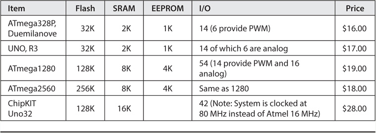
TABLE 1-1 Table of Arduino Microcontrollers
We should point out that the chipKIT Uno32 (pictured in Figure 1-1) is not part of the Arduino family. It is produced by Diligent but is Arduino-compatible in virtually all cases. One reason we include it here is that it is used in the new Rebel transceiver produced by TEN-TEC. To its credit, TEN-TEC has made the Rebel an Open Source project and actively encourages you to experiment with its hardware and software. TEN-TEC even includes header pins for the chip and a USB connector that makes it easy to modify the software that controls the Rebel, which is also Open Source. The Uno32 also has a fairly large amount of SRAM memory and is clocked at 80 MHz versus 16 MHz for the Atmel chips. We have more to say about the chipKIT Uno32 later in the book.
By design, the list presented in Table 1-1 is not exhaustive of the Arduino family. For example, the Arduino Pro Mini is essentially an ATmega328, but it leaves a few features off the board to make it smaller and less expensive. Most notably, the Mini does not have the USB connector on the board. While you can easily work around this, we have enough on our plate that we don’t need to address this issue, too. The absence of a USB port on the board is an important omission because you will transfer the programs you write (called sketches) from your development PC to the Arduino over the USB connection. Further, by default, the Arduino boards draw their working voltages from the USB connector, too. If more power is needed than can be supplied by the USB specs, most Arduino boards have a connector for an external power source. (In Figure 1-1, the “silver box” in the upper left of most boards is the USB connector and the black “barrel shaped” object in the lower left corner is the external power connector.) Therefore, we encourage you to purchase a board from the list in Table 1-1 if for no other reason than to get the onboard USB connector.
As this book is being written, Arduino has announced the Arduino Due board. The Due is the Ferrari of the Arduino boards. It supports 54 I/O ports (12 of which can be used as PWM outputs), 12 analog inputs, 4 UARTs, an 84-MHz clock, a mega-munch of memory plus a host of other improvements. Given all of these cool features, why not opt for the Due? The reason is because the Due is so new, the number of shields and support features just aren’t quite in place yet. Also, it is at least three times as expensive and many of the new features and the additional horsepower will just be idle for the purpose of our projects. Finally, the Due has a maximum pin voltage of 3.3 V, where the rest of the family cruises along at 5 V, making many existing shields unusable on the Due without modification. While we really like the Due, for the reasons detailed here, it is not a good choice for our projects.
Interpreting Table 1-1
So, how do you decide which μC to purchase? Let’s give a quick explanation of what some of the information in Table 1-1 means. First, Flash is the number of kilobytes of Flash memory you have for your program. While 32K of memory doesn’t sound like much, it’s actually quite a bit since you don’t have the bulk of a heavy-duty operating system taking up space. Keep in mind that Flash memory is nonvolatile, which means it retains its state even if power is removed. Therefore, any program code you load into Flash memory stays there until you replace it or there is some kind of board malfunction.
SRAM is the static random access memory available to the system. You can think of it as memory that normally stores variables and other forms of temporary data used as the program executes. It’s a fairly small amount of memory, but since a well-designed program has data that ebbs and flows as it goes into and out of scope, a little thought about your data and what seems like a small amount is usually more than adequate.
EEPROM is the electrical erasable programmable read-only memory. Data stored in EEPROM is also nonvolatile. As stated earlier, most of your program data resides in SRAM. The bank of EEPROM memory is often used to store data that doesn’t get changed very often but is needed for the program to function properly. For example, if your application has several sensors that have to be initialized with specific values on start-up, EEPROM may be a good place to put those start-up data values. On the downside, EEPROM memory can only be rewritten reliably a finite number of times before it starts to get a little flaky. We’ll have more to say about each of these memory types as we progress through the book.
The 328 and Uno μCs have a fairly small number of input/output (I/O) lines available to you. Most are digital lines, but analog lines are also provided. Both of these boards are going to cost a little north of $15. However, if you’re willing to work with a clone from China, these are available for around $10 each. The ATmega1280 and 2560 are similar boards, except for a larger amount of Flash memory and a greater number of I/O pins that are provided. The Diligent chipKIT Uno32 is like the ATmega1280 and 2560 except for a slightly smaller I/O line count and a much higher clock speed. Given that it is the clock speed that plays such an important part in the throughput of the system, the Uno32 is going to perform a set task faster than an Arduino board in most cases.
Making the Choice
Now that you have a basic understanding of some of the features of the various boards available, you should be totally confused and no closer to knowing which μC choice to make. Our Rule of Thumb: The more memory and I/O lines you have, the better. Given that, simply select one that best fits your pocketbook. Most of the projects don’t come close to using all available memory or I/O lines, so any of those in Table 1-1 will work. If you have a particular project in mind, skip to that chapter and see if there are any special board requirements for that project. Otherwise, pick the best one you can afford. (In later chapters, we will show you how to “roll your own” board using a bare chip. This approach is useful when the chip demands are low and the circuitry is simple.)
Having said all that, we really hope you will pick the ATmega1280 or “higher” board, at least for your experimental board while reading this book—the reason being the increased memory and I/O pins. If you develop a circuit that’s pretty simple and a bare-bones 328 would do, you can always buy the chip, a crystal, and a few other components and roll your own 328 board for under $10. (A new μC called the Digispark from Digistump has a one-square-inch footprint yet has 6 I/O lines, 8K of Flash, a clever USB interface yet sells for $9!) However, some of the advanced projects in this book make use of the additional I/O lines, which simplifies things considerably. Therefore, we are going to assume you’re willing to sell pencils on the street for a few days until you get the additional couple of dollars to spring for the 1280 or 2560. You won’t regret it.
By the way, there are a ton of knockoff Arduino’s available on the Internet, mainly from China and Thailand, and we have purchased a good number of them. We have yet to have a bad experience with any foreign supplier. (However, some of them appear to have bootloader software [e.g., the software responsible for moving your program from the host PC to the Arduino] that only work on pre-1.0 Arduino IDEs. Check before you buy.) On the other hand, many times we need a part quickly and domestic suppliers provide very good service for those needs. Appendix A lists some of the suppliers we have used in the past.
What Else Do You Need?
There are a number of other things you need to complete the various projects in this book. One item is a good breadboard for prototyping circuits (see Figure 1-2). A breadboard allows you to insert various components (e.g., resistors, capacitors, etc.) onto the board to create a circuit without actually having to solder the component in place. This makes it much easier to build and test a circuit. The cost of a breadboard is determined in large part by the number of “holes,” or tie points, on the board. The cost of a reasonably sized breadboard is around $20. Most of the breadboards we use have over 1500 tie points on them, although we don’t think we have ever used even 5% of them at once. The board pictured in Figure 1-2 is from Jameco Electronics, has over 2300 tie points, and sells for around $30. Notice the binding posts at the top for voltage and ground connections. You can buy smaller boards with about half the tie points for about half the price. A good quality board should last for years while a really cheap one will wear out and provide weak connection points over time.

FIGURE 1-2 An inexpensive breadboard. (Breadboard courtesy of Jameco Electronics)
The next thing you must have is a soldering iron for when you wish to finalize a circuit. Select an iron with a temperature control and a fairly small tip (see Figure 1-3). You can see a small light area beneath the iron, which is actually a sponge that is soaked with water and then the tip can be scraped on it to keep the tip clean. The small dial allows you to adjust the temperature of the iron. Such an iron can be purchased for around $25 or less.
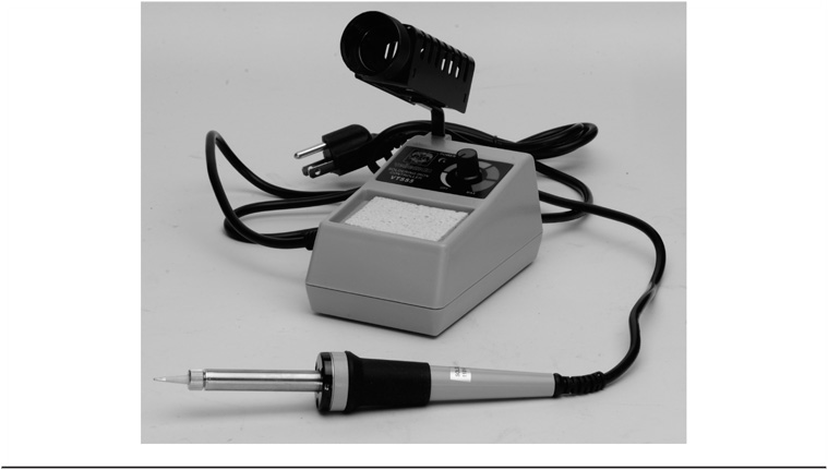
FIGURE 1-3 Adjustable temperature soldering iron.
You will also want a bunch of jumper wires that you will use to tie various components on the board together. Usually, you want jumper wires that run from one breadboard hole to another. These wires have a pin attached to both ends and are called male-to-male jumpers. In other cases, you will want to attach the lead of a device (perhaps a sensor) to the breadboard. In this case, you’ll want one end of the jumper with a small socket-like hole where the sensor lead can be inserted while having a male pin at the other end. These are female-to-male jumpers. Finally, you may have instances where you want both ends to be sockets, or female-to-female jumpers. Jumpers come in various colors and lengths. Personally, it seems we run out of the longer (10 in.) male-to-male jumpers most often. We like the quality of Dupont jumpers (see Figure 1-4) the best.

FIGURE 1-4 Dupont jumpers.
You will also need a variety of resistors, capacitors, wire, solder, cable ties, and a host of other things, depending on your area of interest. Again, your local electronic components store will have most of the components you need. If you can’t find what you need at your local supply store, check Appendix A for a list of suppliers we have found useful.
Software
For most μC projects, software is the glue that holds the project together. In simple terms, there is software that was written by others that you use (e.g., editors, compilers, debuggers, linkers, an IDE, libraries) and there is the software that you write to tell the hardware and other pieces of software what to do. Together, you form a team that is geared toward the solution of some specific problem. In a nutshell, that’s what software development is all about: solving problems. We’ll have a lot more to say about software design and solutions in Chapter 2. For now, we want to get you up and running with a new set of tools.
Downloading and Installing the Arduino Integrated Development Environment
Downloading and installing the Arduino Integrated Development Environment, or IDE, is the first piece of software you need to be able to write your own programs. As this book was being written, Version 1.0.5 is the release number for the current IDE. Now, Version 1.5.6 of the IDE is currently being beta tested, but has not been labeled “stable” yet. However, we have made the switch to 1.5.6 and have not had a problem.
Personally, before downloading the IDE, we prefer to create a matching root directory named in such a way that it is easily identified, such as:
Arduino156
We use this directory as the place to install the software rather than the default directory (which usually ends up under the program directory). The reason for doing this is that it makes it easier to locate certain program, library, and header files should we need to look at them at some time in the future. Note this is just our preference. You are free to place the files wherever you want them.
You can access the Arduino IDE download site by loading your Internet browser (e.g., Internet Explorer, Chrome, Firefox) and then typing the following URL into the address bar:
http://arduino.cc/en/Main/Software
When you get to the download page, you are given download choices for Windows, Mac OS X, or Linux. Select whichever one applies to you. Once started, it may take a while to download the software depending on your Internet download speed. The IDE file, even in its compressed format, is over 56 Mb and even with a fairly fast connection, it still took us almost 10 minutes to download the software.
Installing the Software
When the software is downloaded, move the file (e.g., arduino-1.5.6-windows.exe) to your new working directory (Arduino156 or whatever directory name you have chosen). Now double-click on the file to begin its execution. You will be asked if you want to grant permission to run the software. Press the “Continue” button.
The installer will then ask if you agree to the terms of the license. This is a standard GNU Open Source contract, so you should click the “I agree” button. You should soon see the dialog presented in Figure 1-5.

FIGURE 1-5 Installation options.
You should accept all of the programs to be installed by default. Click “Next.”
The next dialog asks where you wish to install the software, and presents the default folder for installation, as seen in Figure 1-6.

FIGURE 1-6 Default installation folder.
However, since we do not want to use the default installation folder, press the “Browse” button and navigate to the folder you created earlier (e.g., Arduino156). Now click the “Install” button.
It takes a few minutes for the installer to unpack and install all of the associated files. When finished, our installation presented another dialog, as shown in Figure 1-7.

FIGURE 1-7 Install USB device driver.
We checked the “Always trust software from ‘Arduino LLC’” box and then clicked the “Install” button. Within a minute or so, the dialog said “Completed” and we clicked the “Close” button and the installation was complete.
Or was it?
Upon looking in our Arduino156 directory, we found a subdirectory named Arduino that the installer had created automatically. Looking inside of that directory, we found the IDE application file named arduino.exe. We double-clicked the file and were quickly rewarded with the dialog shown in Figure 1-8.
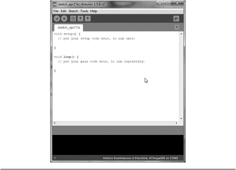
FIGURE 1-8 The Arduino IDE.
Once you see something similar to Figure 1-8, you can be pretty sure you have installed the Arduino IDE successfully. (You may wish to create a desktop shortcut for running the IDE, since you will be using it a lot.)
Running Your First Program
While seeing the image depicted in Figure 1-8 is pretty good a priori evidence that you have installed the IDE correctly, there’s no better proof of the puddin’ than to run a small test program. Fortunately, the IDE comes with a bunch of sample programs you can compile and run.
Connecting Your Arduino to Your PC
The first step in getting your system ready for use is to connect the Arduino board you purchased to your PC. Most Arduino vendors include a USB cable that connects the Arduino board to the PC via the supplied USB cable. This cable supplies power to the Arduino board, plus allows you to transfer your compiled program code from the PC into the Arduino’s Flash memory. Connect the standard USB connector to your PC and the mini connector on the other end to the USB connector on the Arduino board.
Because the Arduino IDE is capable of generating code for different Arduino boards, you need to tell the IDE which board you are using. Assuming you have the IDE up and running, select the Tools → Board → Arduino Mega 2560, as shown in Figure 1-9.
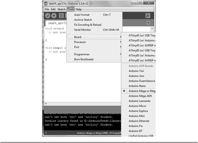
FIGURE 1-9 Selecting the Arduino board within the IDE.
If you purchased a different board, select the appropriate board from the list. If you ever switch boards at a later date, don’t forget to change the board setting to match the new board.
The IDE senses the serial port at this time, too. While our sample Blink program does not take advantage of the serial port, be aware that programs that do have serial communications between the Arduino and your PC must be in sync across the serial port. Although we repeat it later, the default serial baud rate is 9600. Anytime you seem to be getting no serial output from a program, first check to make sure you have the right COM port selected. On the other hand, if the serial communications produce output, but it looks like it came from someone whose native language is Mandarin, chances are the baud rate in your program doesn’t match the serial monitor’s baud rate. You can change the baud rate specified in your program or you can change the baud rate using the serial monitor dialog box. Our preference is to change the baud rate in the program.
Having set up the hardware connection between the IDE and your board, you can now load in the program you wish to compile. Like a bazillion other articles and books, select the sample Blink program that is distributed with the IDE. To load this program, use the File → Examples → 01.Basics → Blink menu sequence as shown in Figure 1-10.
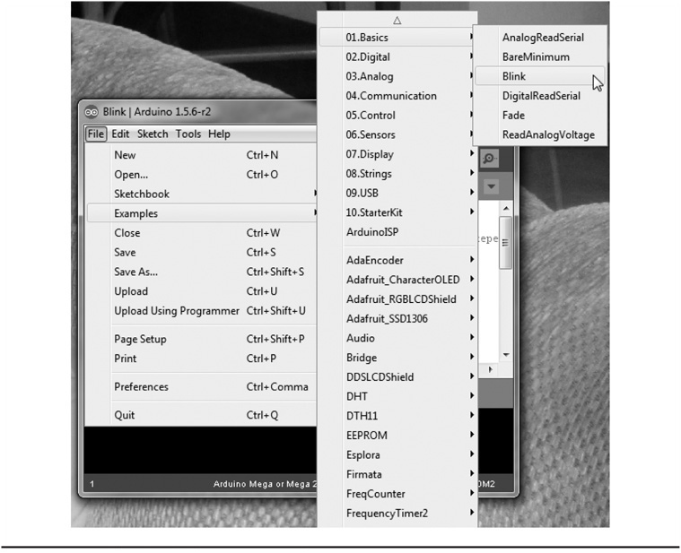
FIGURE 1-10 Loading the Blink program into the IDE.
As soon as you select the Blink program, your IDE should look like that shown in Figure 1-11. While Figure 1-11 shows the Blink program in the IDE, you will also notice an “empty” second IDE in the background. This is normal, as the IDE makes a fresh copy of the IDE when you actually add program source code to it.

FIGURE 1-11 The Blink program in the IDE.
What you see in the IDE is the program’s source code. Source code refers to the human-readable form of the program as it is written in its underlying source code language. For almost all of the programs in this book, we use the programming language named C to write our programs. While you do not have to know how to program in C to use the projects in this book, knowing C makes it easier to edit, modify, enhance, debug, and understand μC programs. In a totally unabashed plug, Dr. Purdum’s Beginning C for Arduino from Apress Publishing is an introductory C programming language book that assumes no prior programming experience. If you want a deeper understanding of what the code does in a given project or simply have a better grasp of how to write your own programs, Beginning C for Arduino is a good starting point. Simon Monk’s Programming Arduino (McGraw-Hill) is also a popular introductory programming book.
Once the program’s source code is visible in the IDE, as in Figure 1-11, you can compile the program. The term compile refers to the process by which the source code language program seen in Figure 1-11 is converted into the machine code instructions that the Atmel processors can understand and execute. You compile the source code by clicking the check mark icon that appears just below the File menu option. Alternatively, you can also use the Sketch → Verify/Compile menu sequence or the Ctrl-R shortcut. If there are no program errors, the IDE should look like that shown in Figure 1-12. Notice the message at the bottom of the IDE. It said it has done compiling and that the Blink program uses 1116 bytes of program space out of a maximum of 30,720 bytes.

FIGURE 1-12 The IDE after a successful compile.
Wait a minute!
If we selected an ATmega2560 with 256K of memory as my board choice, why is there only about 30K of memory left after the program only uses a little over 1K? The reason is: we lied. As we write this, our 2560 boards are “tied up” in other projects, so we’re really using a smaller ATmega328 (often simply called a “328”) we had lying around. Because we really hope you are using an ATmega2560, which was the example board we used in the instructions above. The compiler actually did generate the correct code, but for the board we actually do have attached to the system.
You probably also noticed that the maximum program size is 30,720 bytes. However, if the 328 has 32K (32,768) bytes of Flash memory, where did the approximately 2K bytes of memory go? Earlier we pointed out that μCs don’t have a large operating system gobbling up memory. However, there is a little nibbling away of available memory to the tune of about 2K used up by a program stored in the μC called a bootloader. The bootloader provides the basic functionality of the μC, like loading and executing your program and handling some of the I/O responsibilities.
At this stage, the IDE is holding the compiled program and is ready to send it over the USB cable to the Arduino board. To do this, click the Upload icon, which looks like a circle with a right-pointing arrow in it, just below the Edit menu option. You can also use the File → Upload menu sequence or the Ctrl+U shortcut. Any one of these options moves the compiled program code from the IDE on your PC into the Flash memory on the Arduino board. If you look closely at the board during the upload process, you can see the transmit/receive LEDs flash as the code is being sent to the board. If you’re in a hurry, you can also simply click the right-pointing arrow and skip the (compile-only) check mark icon. If the program source code has changed, the IDE is smart enough to recompile the program and upload the code even though you didn’t click the compile icon.
Once all of the code is sent to the board, the code immediately begins execution. For the Blink program, this means that an LED on the Arduino board begins to blink about once every second. Congratulations! You have just downloaded, installed, and run your first Arduino program.
Now the real fun begins …