13 Landing Systems
13.1 INTRODUCTION
Every successful flight culminates in a landing. Although the majority of landings are conducted solely with visual cues, aircraft must frequently land in weather that requires electronic assistance to the pilot or to the autopilot. This chapter describes the landing maneuver and the electronic systems that provide lateral and vertical guidance to the aircraft relative to the runway chosen for landing. The emphasis is on current systems proposed or in use; historical notes are added when needed for proper perspective.
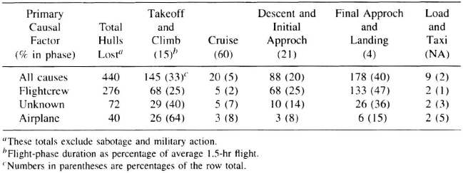
On a normal flight, an aircraft takes off, climbs to cruising altitude, and flies to the vicinity of its destination. There it begins its descent and intercepts the projected runway center line, then makes a final approach and landing with position errors of a few feet in each axis at touchdown (Section 1.5). The approach and landing are the riskiest phases of flight; approximately one-half of the catastrophic accidents occur during these flight phases of which two-thirds are attributed to errors made by the flight crew (Table 13.1). Considering the “exposure times” in the approach and landing phases, the catastrophic-accident probability for any one operation is on the order of 10−8 [1],
13.2 LOW-VISIBILITY OPERATIONS
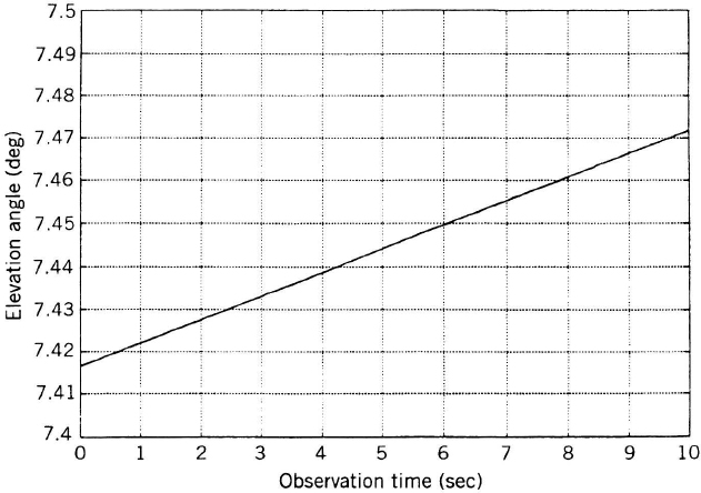
Considerable interference to civil and military operations results due to reduced visibility in terminal areas. For example, Figure 13.1 shows that the visibility at London's Gatwick Airport requires Category II operational capabilities for 115 hours per year and Category III capabilities for 73 hours per year during primary operating hours [2]. Although these hours represent only a few percent on an annual basis, the cost of diverting to an alternate landing site is large. In their 1992–93 fiscal year, KLM estimated savings of $10.3 million (U.S. $) by being able to land 500 flights at the Amsterdam (Schiphol) airport in Category III conditions. During the period 1996 to 2009, KLM estimates costs of $53 million (U.S. $) just for passage if Category III capabilities were not available at Schiphol [3]. While the successful landing of aircraft depends on many factors other than ceiling and visibility, such as crosswinds and storm activity, the term all-weather operations often refers only to operations in condition of reduced visibility [4c].
Table 13.1. Hull-loss accidents by flight phase for the world-wide commercial jet fleet, 1959 to 1990
Instrument meteorological conditions (IMC) are those in which visibility is restricted to various degrees defined by law in certain countries. Aircraft operating in IMC are supposed to fly under Instrument Flight Rules also defined by law. During a landing, the decision height (DH) is the height above the runway at which the landing must be aborted if the runway is not in sight. Usually, the better the electronic aids, the lower is the DH. The International Civil Aviation Organization (ICAO) defines three categories of visibility for landing civil aircraft with the aid of an instrument-landing system [4c]:
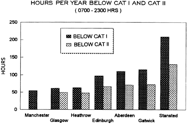
Figure 13.1 Periods of low visibility at major airports in the United Kingdom. 1972 to 1982.
Category I. Decision height not lower than 200 ft; visibility not less than 2600 ft, or Runway Visual Range (RVR) not less than 1800 ft with appropriate runway lighting. The pilot must have visual reference to the runway at the 200-ft DH above the runway or abort the landing. Aircraft require ILS and marker-beacon receivers beyond other requirements for flights under IFR. Category I approaches are performed routinely by pilots with instrument ratings.
Category II. DH not lower than 100 ft and RVR not less than 1200 ft (350 m). The pilot must see the runway above the DH or abort the landing. Additional equipment that aircraft must carry include dual ILS receivers, either a radar altimeter (Section 10.2) or an inner-marker receiver (Section 13.5.5) to measure the decision height, an autopilot coupler or dual flight directors, two pilots, rain-removal equipment (wipers or chemicals), and missed-approach attitude guidance. An auto-throttle system also may be required.
Category III. This category is subdivided into [5b]
• IIIA. DH lower than 100 ft and RVR not less than 700 ft (200 m)—sometimes called see to land; it requires a fail-passive autopilot or a head-up display.
• IIIB. DH lower than 50 ft and RVR not less than 150 ft (50 m)—sometimes called see to taxi; it requires a fail-operational autopilot and an automatic rollout to taxing speed.
• IIIC. Zero visibility. No DH or RVR limits. Category IIIC had not been approved anywhere in the world in 1996.
Aircraft are certified for decision heights, as are crews. When a crew lands an aircraft at an airport, the highest of the three decision heights applies. An abort at the decision height is based on visibility. Another abort criterion is equipment failure; alert height is the altitude below which landing may continue in case of equipment failure. To meet alert height restrictions, either the avionics must be fault-tolerant or the crew must be able to take over manually. A typical alert height is 100 ft.
Additional aircraft equipment may include automatic systems for landing, rollout, and braking. Automatic landing systems must demonstrate satisfactory touchdown dispersion limits in stringent environmental conditions including headwinds to 25 knots, tailwinds to 10 knots, crosswinds to 15 knots, moderate turbulence, and wind shears of 8 knots per 100 ft of height from 200 ft to touchdown. Accidents have resulted when much higher shears (e.g., micro-bursts) have been encountered.
Ceilometers and transmissometers are used at airports to measure terminal-area visual conditions. One version of the latter instrument consists of a light source and a paired photocell, placed 250 or 500 ft apart near the runway. Its indication of visibility is the RVR. As landing minimums are reduced, the measurement of ceiling is less important than slant-range visibility and RVR. Airports at which Category III landings are permitted must be equipped with the standard lighting pattern in Figure 13.2; three transmissometers; outer, middle, and inner marker beacons; and a suitably calibrated instrument-landing system with redundant transmitters. ICAO describes the conditions for permitting Category I, II, and III landings worldwide [4c]. The aircraft and airport equipment required, crew training and means of compliance are published also in FAA advisory circulars [5] and by national aviation authorities in major countries.
13.3 THE MECHANICS OF THE LANDING
13.3.1 The Approach
Day and night landings are permitted under visual flight rules (VFR) when the ceiling exceeds 1000 ft and the horizontal visibility exceeds 3 mi, as judged by the airport control tower. In deteriorated weather, operations must be conducted under Instrument Flight Rules (IFR) [5e]. An IFR approach procedure is either nonprecision (lateral guidance only) or precision (both lateral and vertical guidance signals). Category I, II, and III operations are precision-approach procedures.
An aircraft landing under IFR must transition from cruising flight to the final approach along the extended runway center line by using the standard approach procedures published for each airport [6]. Approach altitudes are measured barometrically, and the transition flight path is defined by initial and final approach fixes (IAF and FAF) using VOR, VOR/DME, Tacan (Chapter 4), and marker beacons (Section 13.5.5). In addition radar vectors may be given to the crew by approach control (Chapter 14).
From approximately 1500 ft above the runway, a precision approach is guided by radio beams generated by the ILS. Large aircraft maintain a speed of 100 to 150 knots during descent along the glide path beginning at the FAF (outer marker). The glide-path angle is set by obstacle-clearance and noise-abatement considerations with 3 deg as the international civil standard. The sink rate is 6 to 16 ft/sec, depending on the aircraft's speed and on headwinds. The ICAO standards [4a] specify that the glide path will cross the runway threshold at a height between 50 and 60 ft. Thus, the projected glide path intercepts the runway surface about 1000 ft from the threshold, as shown in Figure 13.3 [7].
When the aircraft reaches the authorized decision height, the law requires that the crew abort the landing unless it sees the runway or its lights. Note that a DH is not defined for Category IIIC. Figure 13.2 shows the ICAO standard Category II and III lighting pattern for civil airports [4b]. The light bars provide azimuth, roll-and-pitch cues to the pilot. Center line and edge lights provide rollout cues. The typical runway commissioned for precision approaches is 150 ft wide by 8,000 to 12,000 ft long.
For a nonprecision approach, a minimum descent altitude (MDA, 250 to 1000 ft above the runway) is defined below which the aircraft may not descend without visual contact with the runway. The choice of an MDA depends on local obstructions, aircraft type, available navigational aids, and runway lighting [5d].
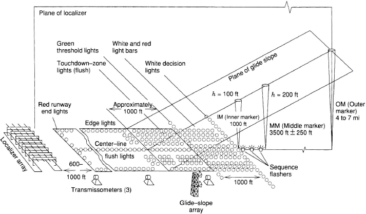
Figure 13.2 Category III runway configuration.
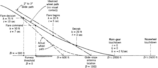
Figure 13.3 Wheel path for instrument landing of a jet aircraft.
13.3.2 The Flare Maneuver
Land-based aircraft are not designed to touch down routinely at the 6 to 16 ft/sec sink rate that exists along the glide path. Thus, a flare maneuver must be executed to reduce the descent rate to less than 3 ft/sec at touchdown.
During approach, the angle of attack is maintained at a value that causes a lift force equal to the aircraft's weight, and the speed is adjusted for a specified stall margin, typically 1.3 times the stall speed plus a margin based on reported wind speed and shear. The flare requires an elevator deflection to increase the angle of attack Δα in order to produce an upward acceleration
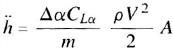
where
| Cl.α | is the derivative of the lift coefficient with respect to angle of attack |
| ρV2/2 | is dynamic pressure (Chapter 8) |
| A | is the wing area |
| m | is the aircraft's mass |
The upward acceleration causes the descent velocity to decrease.
The speed reduction of a typical jet aircraft during flare is 5% to 10% [7]. Reference [7] shows that the flare begins at a wheel height of 30 ft for jet aircraft, requiring that the pilot or autopilot apply the control command 2 sec earlier (because of the lag due to pitch-axis inertia) and that the flare decision point be 1 or 2 sec still earlier. Thus, from the time of visual cue, the flare is prolonged over a 2500-ft horizontal and 75-ft vertical distance, as shown in Figure 13.3.
13.3.3 The Decrab Maneuver and Touchdown
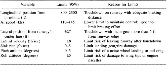
In a crosswind Vcw, an aircraft will approach with a crab angle b such that its ground-speed vector lies along the runway's center line. At an approach airspeed Va and a headwind Vhw, sin b = Vcw/(Va − Vhw); b is usually less than 5 deg and is always less than 15 deg. Near touchdown, the aircraft can decrab, slip, or execute a combined decrab-slip maneuver, as explained in Section 13.4.3. After the decrab, the wind causes the aircraft to begin drifting across the runway. For large aircraft, decrab typically occurs 2 to 3 sec prior to touch-down. It must occur late enough for the yaw rates and adverse roll to be nulled, but not so late as to result in appreciable lateral-drift speed or displacement. The slip consists of (1) lowering the upwind wing to compensate for drift and (2) holding enough opposite rudder to prevent the aircraft from turning and to keep it flying at the same heading as the runway; slip is initiated 200 to 400 ft above the runway. Reference [8] reports simulations showing that pilots will tolerate roll angles as large as 3 degrees below 100-ft altitude if the visibility is less than 700 ft, and up to 5 degrees if the visibility is greater than 1200 ft. Many large transports cannot roll more than 10 deg without striking a wingtip or engine on the runway. Reference [8a] discusses the aerodynamics of decrab in detail. Sections 13.4.2 and 13.4.3 discuss autopilot-coupled flare and decrab just prior to touchdown. The constraints to be satisfied for an acceptable landing are shown in Table 13.2 [9].
Table 13.2 Acceptable range of variables at touchdown for jet transport aircraft
13.3.4 Rollout and Taxi
Approximately 600 ft after main-gear touchdown [7], a large jet aircraft lowers its nose wheel and subsequently behaves like a ground vehicle. It must complete its rollout within the boundaries of the runway, locate an exit, and follow the taxiway to the apron. As operational visibility decreases, the ground movement requirements become more severe. Some methods for guiding aircraft on taxiways include the following:
- Runway stopping-distance can be measured with distance-measuring equipment (DME, Chapter 4) located with the localizer.
- Systems that modulate taxiway lights to guide an aircraft along a specific taxi route. Lighted signs are located at intersections; reprogrammable signs could be installed.
- Surface movement radars (Airport Surface Detection Radar in the United States) that aid in avoiding taxiway and runway-incursion accidents. Identifying aircraft and vehicles is a problem, because these radars have no transponder mode.
- Transponder-based systems that derive positions on the airport from the aircraft's transponder replies to interrogators located with taxiway lights. The surveillance data are relayed to controllers.
- Radio broadcast of on-board derived position and velocity (e.g., from GPS). If all vehicles were so equipped, the ground controller could more effectively prevent runway incursions and collisions on the ground.
- Milliwatt marker-beacon transmitters placed at all runway thresholds would give a visual and audible alarm on the flight deck of any aircraft that taxied onto an active runway. This would reduce the likelihood of a lost pilot causing a catastrophic collision.
It is mandatory that fire and rescue vehicles be able to locate disabled aircraft on the field in low visibility. Aircraft must be moved to ramps, hangars, maintenance areas, and fueling areas during periods of low-visibility landing. Except in military operations, a visibility limit exists below which aircraft operations are no longer practical because of the inability to move passengers and cargo from the airfield. The need for Category III (especially IIIC) landing by civil air carriers is tied to these supporting capabilities.
13.4 AUTOMATIC LANDING SYSTEMS
Air carrier aircraft that are authorized for precision-approach below Category II must have an automatic landing (auto-land) system. Extended-vision devices such as head-up displays improve the pilot's ability to monitor the approach and can substitute for autoland, at least to Category IIIA. In the 1990s many air-carrier aircraft such as MD-80, MD-11, A-300 Series, Boeing 757, 767, 777 were equipped with auto-land systems that were certified to Category IIIA or HIB [5b]. Below the DH, neither a manual nor an automatic go-around is permitted because of the risk of ground contact; the landing must continue.
In 1967, the first fully automatic landings were made in airline passenger service [10]. The Blind Landing Experimental Unit (BLEU) of the Ministry of Defence in the United Kingdom had been very active during and after World War II. The economic incentives of expanding commercial air operations after the war provided the motivation for auto-land system development. Even with the certification of air carrier aircraft for automatic landings, DHs were not lowered below 100 ft until the reliability and failure-detection capability (integrity) of the aircraft (e.g., propulsion, flight control, auto-land) and ground guidance had been proven and standards agreed.
In the early 1970s the British Trident and the U.S. L-1011 aircraft (including their auto-land systems) were certified for Category Ilia operations in revenue service using guidance information from the ILS and from other on-board sensors [11]. Many airliners were certified thereafter. In 1996, Category III operations were “automatic-to-touchdown,” based on the use of auto-land systems that do not require pilot intervention [5b]. These Categories have been developed, defined, and agreed internationally in a generic manner to allow innovation in meeting the requirements.
13.4.1 Guidance and Control Requirements
The FAA regulations for Category II approval [5a] require that the coupled autopilot or crew hold the aircraft within the larger of ±12 ft or ±35 μamps (measured by the ILS glide slope) of the glide path from 700 ft down to the 100-ft DH. This corresponds to a vertical error of ±38 ft (2-sigma) at the 700-ft height and ±12 ft (2-sigma) at the 100-ft height on a 3-deg glide path. For Category III certification, the allowable touchdown dispersions also are specified. The demonstrated touchdown dispersions should be limited to 1500 ft longitudinally and ±27 ft laterally on a 2-sigma basis [5c].
Paralleling the improvement in accuracy was the development of systematic methodologies for conducting hazard analyses. Thus, in addition to the operational concepts, an acceptable level of risk needs to be specified as the starting point for a hazard analysis of the aircraft and ground navigation systems. At its simplest, the probability of a catastrophic event during a Category III landing should not be greater than it is for a visual approach and landing [12]. Historical accident rates and the characteristics of modern turbojet aircraft suggest that less than one fatal accident should occur in 107 flight-hours, due to all systems, a number generally agreed upon by the designers of civil transports. Thus the probability of a catastrophic event due to an individual subsystem (e.g., autoland) is closer to one event in 109 flight-hours, a time interval that is likely to exceed the cumulative fleet life of any transport model.
Airport equipment in Category II, IIIA. and IIIB. differ only in the extent of failure detection and automatic reconfiguration following failure.
13.4.2 Flare Guidance
During the final approach the glide-slope gain in the auto-land system is reduced in a programmed fashion (called gain scheduling). Supplementary sensors must supply the vertical guidance below 100 ft.
In the 1990s, automatic landing systems used height and height-rate data from redundant radar altimeters (Section 10.2), frequently complemented with inertial sensor data, to accomplish this flare maneuver. Low-range radar altimeters have a nominal accuracy of 1.5 ft (2 sigma) below 100 ft altitude and 2% of full scale at higher altitude (Section 10.2.4). They have a low-noise output that allows the derivation of vertical rate information. The ILS cannot develop similar information, since the glide-slope receiver provides deviations from the zero-DDM glide path which is not at a constant height across the width of the localizer course/runway (Section 13.5). Therefore, accurate calculation of aircraft height using the glide-path deviations and distance information from a stop-end DME (Section 4.4.6) is not practical.
The flare command is initiated at a wheel height of about 75 ft, well before the runway threshold. However, the radar altimeter may not be usable prior to threshold due to uneven terrain or tidal variations. Typically, auto-land systems cover the gap between flare initiation and the beginning of altimeter coverage over the paved runway (50-ft height) with data from on-board inertial-navigation systems (Chapter 7).
The flare is an exponential path tangent to a horizontal plane several feet below the runway, which ensures positive touchdown. The desired height-rate at touchdown is included in the calculation of steering signals, so that the touchdown point and vertical velocity at touchdown are repeatable. A typical vertical rate command is ![]() , where h and
, where h and ![]() are the measured instantaneous altitude and altitude rate [8b].
are the measured instantaneous altitude and altitude rate [8b].
13.4.3 Lateral Guidance
In 1996, ILS localizers met Category-Ill performance requirements for landing and rollout guidance at many locations. Tracking of the localizer is aided by heading (or integral-of-roll), roll, or roll-rate signals supplied to the autopilot (Section 2.7.3) and by rate and acceleration data from on-board inertial systems. During most of the approach in a crosswind, the wings are level and the aircraft points into the wind (crabbed) so that its velocity vector tracks the localizer. The localizer gain must be scheduled to decrease as the runway is approached because the surfaces of constant DDM (Section 13.5) converge to make the error signal more and more sensitive to distance displacement.
The aircraft should touch down with its axis along the runway's center line to avoid side forces on the landing gear. To do this in Category I and II conditions, the crew can slip or decrab manually before touchdown. In lower visibility, when landing operations may be automatic to touchdown, the slip and crab are mechanized by feeding the appropriate elevator and rudder commands to the autopilot approximately 200 ft above the runway. This establishes as much slip as needed, but not more than about 5 deg roll for a typical commercial airliner, thus reducing the crab angle that was established on approach. If the crosswind is so high (above about 10 knots) that the roll angle exceeds about 5 deg, a decrab maneuver is inserted about 15 ft above the runway to point the aircraft axis along the runway. The velocity vector must be within 3 deg of the runway axis at touchdown to keep the aircraft on the runway. For example, a 40-ft lateral touchdown error (FAA 3-sigma requirement) and a 3 degree lateral flight-path error could cause an aircraft with a 20-ft landing-gear spread to leave a 150-ft wide runway in about 2.5 sec.
13.5 THE INSTRUMENT LANDING SYSTEM
The instrument landing system (ILS) is a collection of radio transmitting stations used to guide aircraft to a specific airport runway, especially during times of limited visibility. High-density airports may be equipped on more than one runway—Chicago's O'Hare airport had an ILS installed on 12 runways in 1996.
First commercially used in 1939, ILS has been in civil use for the equivalent of Category I landings since 1947 [13] and had been certified for Category II (1960s) and Category III (1970s) operations at many major airports. About 1500 ILSs are in use at airports throughout the world with U.S. airports, accounting for more than 1000 of these. In 1996, nearly 100 airports worldwide had at least one runway certified to Category III. There were approximately 117,000 aircraft worldwide with one or more ILS receivers.
The ILS development worldwide was aided by the publication of signal standards by the International Civil Aviation Organization (ICAO, created in 1944). The ICAO Standards and Recommended Practices (SARPs) [4a] for the ILS, subscribed to by the 180 member states, standardize the signal in space of the ILS ground transmitting equipment, no matter where they are manufactured, to ensure compatibility on international flights. The FAA and RTCA publish manuals for ILS equipment in the U.S. national airspace system that ensure conformance to ICAO standards [18]. In Europe, the Joint Aviation Authority (JAA) and EUROCAE do the same [31]. U.S. receivers are standardized by Aeronautical Radio, Inc. [32].
Typically, an ILS includes
- the localizer antenna is centered on the runway beyond the stop end to provide lateral guidance
- the glide slope, located beside the runway near the threshold to provide vertical guidance
- marker beacons located at discrete positions along the approach path; to alert pilots of their progress along the glide-path
- radiation monitors that, in case of ILS failure alarm the control tower, may shut-down a Category I or II ILS, or switch a Category III ILS to backup transmitters (Figure 13.2).
Increasingly, distance measuring equipment (DME) (Chapter 4) is located with the ILS, and distance readouts in the cockpit are used instead of marker beacons.
13.5.1 ILS Guidance Signals
The localizer, glide slope, and marker beacons radiate continuous wave, horizontally polarized, radio frequency energy. The frequency bands of operation are: localizer, 40 channels from 108–112 MHz; glide slope, 40 channels from 329–335 MHz; and marker beacons, all on a single frequency of 75 MHz. An audible Morse-code identification signal is transmitted on the localizer frequency; a voice channel from the control tower also may be provided. The localizer, glide slope, and DME frequencies are paired such that, for example, an ILS with a localizer frequency of 109.5 MHz has a glide slope frequency of 332.6 MHz and has channel 32× for the DME, if installed. This hard pairing reduces the pilot's work load, since only the localizer frequency need be entered to tune the ILS and associated DME.
The localizer establishes a radiation pattern in space that provides a deviation signal in the aircraft when the aircraft is displaced laterally from the vertical plane containing the runway center line [18d]. This deviation signal drives the left–right needle of the pilot's cross-pointer display (or flight director) and may be wired to the autopilot/flight-control system for “coupled” approaches.
To form the localizer course, an RF carrier is generated in the transmitter and amplitude modulated with discrete 90-Hz and 150-Hz tones to create equal-amplitude sidebands placed 90 Hz and 150 Hz above and below the carrier frequency. This “carrier-with-sidebands” (CSB) signal is radiated from the localizer array in a broadside “sum” pattern that provides general coverage of the approach course area. Simultaneously, some of the sideband energy is separated from the carrier and shifted in phase to provide a “sidebands-only” (SBO) signal. The SBO signal is radiated from the same array in a “difference” pattern, and the sharp null, characteristic of the difference pattern, is aligned with the runway center line. The lobes of the difference pattern (and thus the 90-Hz and 150-Hz sidebands) are opposite in phase on either side of the center line null (Figure 13.4).
The net result is that, on centerline where the SBO signal is nulled, only the equal-amplitude sidebands of the CSB signal are detected and the receiver provides an “on-course” output. Either side of center line, the SBO signal amplitude increases rapidly and unbalances the CSB sidebands such that a 90-Hz sideband will dominate to the left of course and a 150-Hz sideband to the right. The total signal modulation M is defined as M = (A+B)/C, where A and B are the amplitudes of the 150- and 90-Hz signals respectively, and C is the amplitude of the carrier [14]. The difference in depth of modulation (DDM) is (A − B)/C. The ILS receiver measures the magnitude of this DDM and outputs a “deviation-from-course” signal. Thus, the cross-pointer course-deviation (CDI) needle or flight director shows “fly right” when the 90-Hz tone dominates and “fly left” when the 150-Hz tone dominates.
The deviation signal is proportional to azimuth angle usually out to 5 deg or more either side of the center line. The ICAO standards [4a] require that a DDM of ±0.155 cause a full-scale needle deflection and that this DDM value occur at 350 ft on either side of the center line at the approach threshold. Thus, with different runway lengths, the angular course width from the localizer will be 3 deg to 6 deg, as set by adjusting the radiated sideband power.

Figure 13.4 Sum and difference radiation patterns for the course (CRS) and clearance (CLR) signals of a directional localizer array.
The ICAO standard is that full-scale deviation signals be provided to 35 deg either side of center line to aid acquisition of the zero-DDM course. If the localizer CSB pattern is narrow (e.g., 5 deg to 10 deg), to reduce reflections from buildings and other aircraft, the system requires the addition of “clearance” signals to provide the ±35 deg coverage. These clearance signals are added by providing a second set of CSB and SBO signals radiated from a shorter array with a broad-coverage pattern. A two-frequency “capture-principle” method may be used to reduce the interference effects on the course signal due to clearance signal reflections from, for example, large hangars at the wide angles.
The frequencies of the two RF carriers are spaced a nominal 8 kHz and are offset symmetrically about the channel center frequency. The two sets of signals (course CSB and SBO and clearance CSB and SBO) are within the 25-kHz passband of the receiver and are detected. A basic characteristic of the linear AM detector is that, with two modulated carriers present, the demodulated course information greatly favors (captures) the even slightly stronger carrier signal. The airborne receiver, when near the center line, receives two carrier frequencies each with 90- and 150-Hz modulations. The weaker clearance signals reflected into the course region are received along with the stronger course signal and thus have less influence on the detector output. Because this “capture principle” can reduce the course roughness due to clearance-signal reflections by a factor of 3 to 10, two-frequency systems are needed at most airports where higher-category landing minimums are desired. For Category IIIB and IIIC operations, the localizer signal is used along the runway for rollout guidance. ILS ground equipment being procured by the FAA in the mid 1990s are two-frequency designs that can support Category II and III operations. The localizer accuracy required to support the three ILS performance categories is shown in Table 13.3 [4a].
With regard to the vertical guidance signals, the glide slope in most respects can be considered as a localizer on its side. The minimum coverage extends approximately 10 nmi from threshold, to 8 deg on either side of center line, and up to 5000 ft for the nominal 3 deg path angle. Given a nominal angle and height at runway threshold, the linear glide path extension intercepts the runway surface approximately 1000 ft inside the threshold (Figure 13.2) [18e],
Table 13.3. ILS guidance errors allowed by ICAO standards (ft)
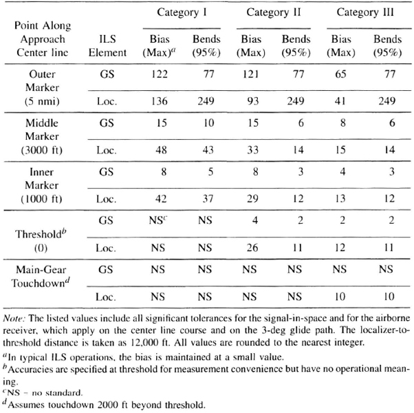
The sideband arrangement is for the 90-Hz signal to predominate above the glide path and the 150-Hz signal to dominate below (Figure 13.5) [16]. The relative signal amplitudes are such that full-scale needle deflection and a DDM = ±0.175 exist at ±θ/4 (±0.75 deg for θ = 3 deg glide path) [4a], The vertical deviation indicator (VDI) needle reads full-scale “fly up” for all downward departures exceeding θ/4 and full-scale “fly down” for upward departures exceeding θ/4 to as high as 3θ. The glide-slope accuracies required to support the three ILS performance categories are shown in Table 13.3 [4a].
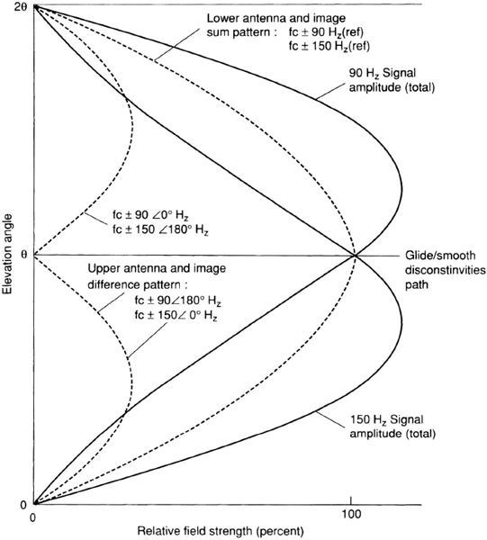
Figure 13.5 Vertical beam patterns of the null-reference glide-slope array.
13.5.2 The Localizer
The typical localizer is an array of antennas usually located 600 to 1000 ft beyond the stop end of the runway. The array axis is perpendicular to the runway center line, and the localizer zero-DDM course is aligned with the runway center line extended (Figure 13.2). Localizer arrays range from 40 to 130 ft in length on which are mounted from 6 to more than 20 antennas. Some localizers are bi-directional and provide lateral steering signals for both the normal front-course approach and for a back-course approach in the opposite direction (at which the steering signals are reversed).
Although there are three different types of antenna elements in use, all modern arrays and new procurements by the U.S. FAA use the log-periodic-dipole (LPD) antenna which provides uni-directional radiation (Figure 13.6). It is 9 ft long, can be installed without guy cables, and has good broad-band characteristics. Each dipole is driven by a balanced transmission line within the horizontal supporting structure which, in turn, is fed from a matching network at the forward end [5g]. Also within this structure, a parallel transmission line samples signals from the seven dipole arms for the integral monitor. Plans exist to modify this antenna in order to make it bi-directional for use where a back course is desired.
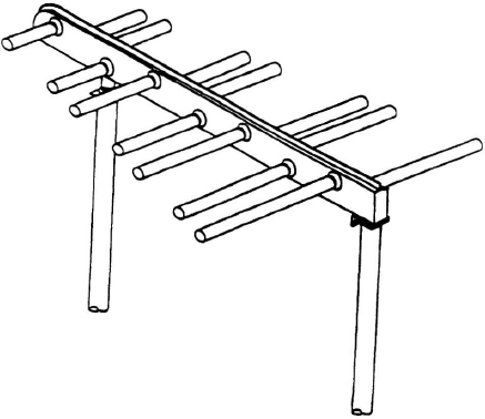
Figure 13.6 Log-periodic dipole antenna used in many localizer arrays.
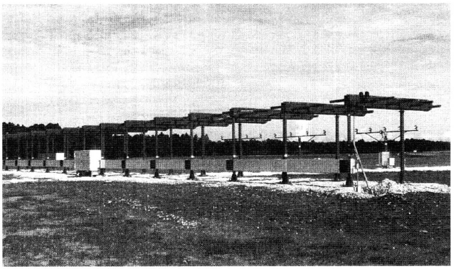
Figure 13.7 Category IIIB localizer (courtesy, Wilcox Corporation).
Clearance signals, where required (Section 13.5.2), may be provided by a separate array or, in some designs, both course and clearance signals are radiated from several elements of a single array. A Category III localizer with LPD elements is shown in Figure 13.7.
13.5.3 The Glide Slope
There are five different types of glide-slope arrays in common use; three are image systems and two are not. Image arrays depend on reflections from level ground in the direction of approaching aircraft to form the radiation pattern. The three image systems are the null-referenee system, with two antennas supported on a vertical mast 14 and 28 ft above the ground plane; the sideband-reference system, with two antennas 7 and 22 ft above the ground plane; and the capture-effect system, with 3 antennas 14, 28, and 42 ft above the ground plane.
The operating principles of each image array are similar. A two-element array is formed by the CSB antenna and its image below the ground plane. The height of the CSB antenna is chosen so that the direct signal and the image signal will add and form a “sum” radiation pattern. Similarly, the SBO antenna is placed on the mast so that the array formed with its image provides a “difference” radiation pattern with the null at the desired glide-path angle.
Because each antenna and its image form a two-element interferometer, multiple lobes are produced in the broad-side (vertical) radiation patterns. Thus, false nulls exist at 2θ, 3θ, 4θ, etc., but the steering errors show “fly down” on both sides of 2θ, “fly away” at 3θ, and “fly up” on both sides of 4θ. The first stable null is at 5θ, where the steering signals are again correct. The steepness of that stable false glide path (15 deg for a 3 deg glide slope) makes it easy to distinguish from the true glide path.
The most capable of the image glide slopes, the capture-effect array (Figure 13.8), is designed to cancel the CSB signal below about 1.5 deg in order to reduce the energy reflected from rising terrain under the approach course. To provide a strong fly-up signal, a 150-Hz clearance signal is radiated below the glide path on a separate carrier, offset in frequency, and use is made of the “capture principle” (Section 13.5.2) to reduce the interference due to reflections of the clearance signal from the terrain.
As shown in Figure 13.9, the zero-DDM surface for image arrays is the hyperboloid of revolution whose axis of symmetry is approximately the glide slope mast [17]. Note that, due to the use of the antenna images, this zero-DDM surface does not extend to ground level, although the origin of its asymptotic cone is near the bottom of the mast. The half-angle of the asymptotic cone is 87 deg for a 3 deg glide path. A vertical plane containing the runway center line intersects the zero-DDM hyperboloid in a hyperbola whose asymptote is the ideal (linear) glide path. Because the glide-slope array is offset from center line, the zero-DDM contour is 1 to 3 ft above the (straight-line) asymptotic glide path at the inner marker, 2 to 6 ft above at the threshold of a 150-ft-wide runway, and 15 to 23 ft above the runway opposite the glide-slope mast (for an array mounted 400-ft from center line).
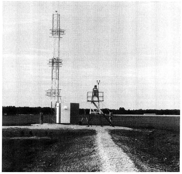
Figure 13.8 Category IIIB capture-effect glideslope and Tasker transmissometer (courtesy, Wilcox Corporation).
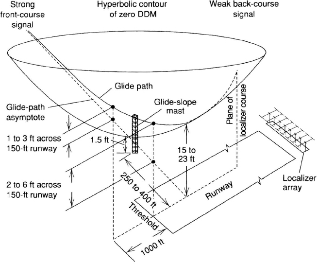
Figure 13.9 Glide-slope pattern near the runway [17]. DDM contours are symmetrical around the vertical, but signal strength drops rapidly off course.
The performance of the image glide slopes depends on the characteristics of the terrain in front of the array. A minimum ground plane extending 1000 ft in front of the array and varying not more than 12 in. from level(![]() wavelength) is required. To accommodate sites where this ground plane cannot be provided, two non-image systems have been developed:
wavelength) is required. To accommodate sites where this ground plane cannot be provided, two non-image systems have been developed:
- The wave-guide glide slope is a broadside array of slotted-wave-guide radiators with a vertical aperture of some 70 ft. There were a small number in service in the United States in 1996; one was installed on Runway 23 at Buffalo Internationa] Airport, New York. By tilting the array out of the vertical by the amount of the glide-path angle, the zero-DDM surface may be planar rather than hyperbolic.
- The end-fire glide slope (EFGS) became available for installation at difficult sites late in the 1970s. This system uses two horizontal coaxial cables, each with 96 radiating slots, to form an array of 96 antennas. The cables are laid almost perpendicular to the runway's center line and separated such that the radiation from one slot in the front cable and the corresponding slot in the rear cable are in phase and form a conical radiation pattern which contains the glide path (Figure 13.10). The 450 ft spacing of the front and rear cables creates a zero-DDM surface, which is a cone with a 6-deg vertex angle in the far-field. The pattern created by any single end-fire pair would not be satisfactory for glide-path guidance, because the cone would intersect the ground at 3 deg on either side of the localizer course. However, 96 of them merge to form a broad glide-path. Two additional slotted cables and the two-frequency “capture principle” provide strong fly-up commands on either side of the localizer course area.
The cable radiators of the end-fire array are installed on stands 40 in. high and are sited alongside the runway near the desired touchdown point (Figure 13.11). In 1996, 15 such systems were in operation worldwide with approximately 3 systems added each year.
The closest portion of the end-fire antennas is only 25 ft from the edge of the runway. The sideband reference mast is usually about 185 ft from the edge, and the null-reference and capture-effect antenna masts are 275 to 325 ft from the edge. The tall wave-guide array is laterally offset from the runway by about 1,000 ft.
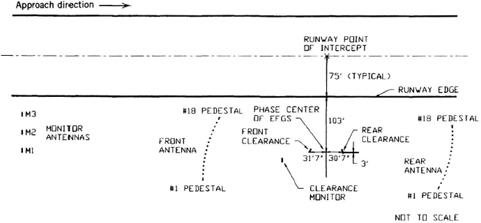
Figure 13.10 Standard end-fire glide-slope system layout.
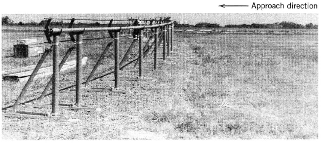
Figure 13.11 Front slotted-cable radiator of an end-fire glide slope (courtesy. Watts Antenna Company).
13.5.4 ILS Marker Beacons
Marker beacons provide pilot alerts along the approach path. Each beacon radiates a fan-shaped vertical beam that is approximately ±40° wide along the glide path by ±85° wide perpendicular to the path (half-power points). The outer marker (OM) is placed under the approach course near the point of glide-path intercept (distance varies from 4 to 7 nmi from the threshold). It is modulated with two 400-Hz Morse-code dashes per second. The middle marker (MM) is placed near the point where a missed-approach decision would need to be made for a Category I approach procedure (nominally 3000 ft from the threshold). The middle marker is modulated with one 1300-Hz dash-dot pair each second. The inner marker (IM) may be required at runways certified for Category II and III operations and is placed near the point where the glide path is 100 ft above the runway (nominally 1000 ft before threshold). The inner marker has six dots per second at 3000 Hz. Typically, marker-beacon transmitters are mounted off airport property on masts 2 to 10 ft high and are unattended.
The use of marker beacons is decreasing. Real estate for installation is a major problem. The increased use of DME in conjunction with the ILS has diminished the pilot's dependence on the markers, as will the increasing availability of Loran-C and GNSS for IFR navigation.
13.5.5 Receivers
The typical aircraft receiver is a double-conversion, superheterodyne design with an AM detector. Filters after the detector separate the 90- and 150-Hz tones which, in the most basic circuit, are rectified and fed to a dc microam-meter. The meter needle deflects in a direction corresponding to the stronger of the two tones. A DDM of 0.175, with a larger 90-Hz modulation (left of course), produces 150 μ of current and deflects the course needle to the full-scale limit on the right (“steer right”). On the right side of the course, the 150-Hz modulation dominates with a corresponding needle deflection to the left. The arrangement for the glide path vertical needle is similar. Glass displays emulate needles. When approaching in the opposite direction on the back course, the course needle deflections are reversed (a right deflection means “steer left”). No glide-path signals are present in the back course.
The marker-beacon receiver is a dedicated crystal controlled receiver, fixed-tuned to 75 MHz. Most have audio filters that control colored lights in a cockpit indicator. Thus, in addition to the audible tones, the outer marker lights a purple lamp on the instrument panel; the middle marker, an amber lamp; and the inner marker, a white lamp.
Closely harmonized airborne equipment standards and specifications are produced by RTCA [18] and ARINC in the United States [32b] and by EUROCAE [31] in Europe.
13.5.6 ILS Limitations
The major limitation of ILS is its sensitivity to the environment. At the ILS operating frequencies, the very narrow beam widths, necessary to avoid significant illumination of the environment surrounding the approach course, require array structures which are too large to be practical. Accuracy degradations (beam bends) due to reflections from buildings, terrain, airborne aircraft, taxiing aircraft, and ground vehicles are the result. The problem is particularly stressful for the glide-slope array, where the shallow elevation angle of the glide path requires large apertures in order to reduce ground reflections sufficiently to meet the stringent vertical error limits close to runway threshold. These reflected (multipath) signals mix with the direct signal at the aircraft and cause bends in the glide path (the received signal is the instantaneous sum of all energy arriving at the aircraft's antenna, including reflections, Figure 13.12). The use of image arrays helps to reduce the glide slope's physical size but requires an extensive area of terrain along the direction of the approach to be flat within ![]() wavelength (about 1 ft). To achieve Category II and III operations, the glide path must be free of sharp bends (though not necessarily straight) down to a height of 50 ft (threshold), where the allowed 95% error of ±4 ft is evenly divided between bias and bend components (Table 13.3).
wavelength (about 1 ft). To achieve Category II and III operations, the glide path must be free of sharp bends (though not necessarily straight) down to a height of 50 ft (threshold), where the allowed 95% error of ±4 ft is evenly divided between bias and bend components (Table 13.3).
The small vertical aperture of typical localizer antenna elements creates an omni-directional vertical pattern. Reflections from aircraft taking off (or executing a missed approach) can cause bends of ±20 μamp (±0.3 deg = ±60 ft laterally 2 nmi from the localizer) that persist for as long as 10 sec [13]. Such bends combined with the localizer error estimate of ±22ft at the threshold of a long runway (Table 13.3) could move the course outside the runway edges. The overflight errors are controlled during instrument operations by increasing the spacing between aircraft approaching and departing.
Aircraft and vehicles on the airport surface, especially on taxiways near the antennas, can reflect ILS signals and cause significant errors along the approach path. Experience has shown that reflection errors can be eliminated only by prohibiting traffic in sensitive regions of the airport during periods of low-visibility operations. Activation of these “critical and sensitive areas” reduces the airport capacity [5g].
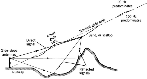
Figure 13.12 Formation of bends in the glide path.
The localizer is subject to interference from strong FM stations. This is a particular problem in congested Northern Europe. The ICAO has issued standards for ILS receivers with improved FM rejection characteristics, effective in 1998.
13.6 THE MICROWAVE-LANDING SYSTEM
During the late 1960s, the requirements of civil aviation were forecast to exceed the capabilities of the ILS. The U.S. military services, for more than a decade, had been developing microwave approach guidance systems to support tactical deployments and aircraft-carrier operations (Section 13.8). In 1974, the ICAO solicited proposals from member states for a new guidance system to replace the ILS as the international standard for civil aviation [4d].
Designs were sought that retained the desirable features of the ILS while mitigating its weaknesses. The runway-resident architecture of ILS was carried forward to MLS, because, as the landing aircraft approaches the runway, linear offsets (due to errors in the angular guidance) continually decrease, while the signal-to-noise ratio generally increases. Thus, in the most demanding phase of flight close to the ground, the positional accuracy is constantly improving and the noise content is generally decreasing.
The main weakness of the ILS, its sensitivity to the environment (Section 13.5.6), would be essentially eliminated by narrow beam-width antennas that are physically small at microwave frequencies. As a result, a single-accuracy standard, equivalent to Category III ILS, was chosen for MLS. Also, at microwave frequencies, the lack of available channels, which limits multiple ILS deployments in metropolitan areas, would no longer be a problem.
In 1978, ICAO recommended the Time-Reference Scanning Beam MLS proposed by Australia and the United States. In 1985, ICAO adopted the MLS standard and endorsed a transition from the ILS to the MLS beginning in 1998. However, in the spring of 1995, recognizing satellite navigation applications to precision landing, ICAO recommended that standards for both ILS and MLS should stand for the next 15 to 20 years, along with anticipated standards for satellite-based landing systems. In 1987, ARINC issued a specification for an MLS receiver [32c], and, in 1995, EUROCAE issued a specification for a combined ILS-MLS receiver [31].
13.6.1 Signal Format
A basic MLS consists of azimuth and elevation ground stations and a conventional DME (Section 4.4.6) for 3D positioning on approach courses to 40 deg on either side of center line and to 15 deg elevation above the runway. An expanded MLS may include a back-azimuth station for departure/missed-approach lateral guidance to ±40 deg of center line, additional approach coverage to ±60 deg of center line, and a more accurate DME (DME/P, Section 13.6.6).
The MLS ground stations transmit both angle and data functions (messages) on one of 200 frequencies between 5031.0 and 5190.7 MHz, Figure 13.13 [4a], Each transmitted function begins with a differentially encoded binary preamble, modulated by 2-state phase-shift keying. The preamble establishes the carrier phase in the airborne receiver for decoding the preamble message, provides a 5-bit correlation (Barker) code as a timing reference, and identifies the function (e.g., elevation angle) being transmitted. Preambles are radiated from low-gain, fixed-pattern antennas at the azimuth (Az) and elevation (El) stations that fill the approach coverage volume. Therefore, the acceptable bit-error rate of the differential phase-shift key (DPSK) transmissions at the 20-nmi limit determines the transmitter power (about 20 w) needed in the ground stations.
13.6.2 The Angle Functions
The requirement for proportional angle encoding throughout broad coverage sectors is achieved by scanning a narrow antenna pattern. For Az antennas, the antenna beam width may be chosen so that, when the aircraft is near the extended center line, undesirable (multipath) reflections from large hangars along the runway will arrive at the airborne antenna earlier or later than the desired (direct-path) signal. Similarly, for elevation antennas scanning vertically, the antenna beamwidth is chosen to avoid interference from signals reflected from the ground when scanning to the lowest required elevation angle, Figure 13.14. Note that reflected energy can arrive before direct energy if the scanning beam illuminates a nearby object before it illuminates the landing aircraft.
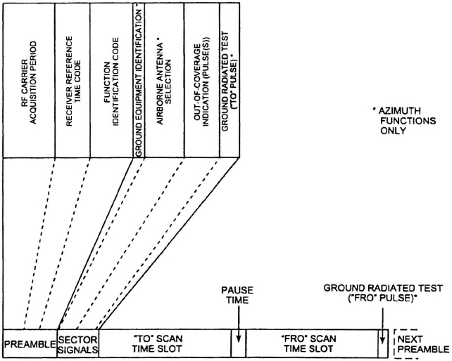
Figure 13.13 Transmission of angular information, MLS.
Early military MLS with mechanically scanned antennas used a varying audio tone (or a pulse train) to encode the pointing angle on the scanning-beam pattern. The particular audiofrequency (or pulse code) modulation on the RF carrier, which represented the instantaneous pointing angle, was detected when the scanning pattern illuminated the aircraft's MLS antenna (Section 13.8.3). The FAA adopted time interval between successive passages of the unmodulated beam as an efficient method of angle encoding. This reduced spectral requirements and was compatible with high (electronic) scanning rates. In this system, the angle coding is a linear function of time, as follows:
![]()
where θ is the azimuth or elevation guidance angle in degrees, V is the scan velocity (typically 20 deg/msec). T0 is the value of the time difference at the vertical center line plane (Az functions) or at the horizontal plane through the phase center (El functions) in milliseconds, and t is the time interval in milliseconds between TO and FRO passages of the beam centroid at the aircraft. A complete angle-transmission format is shown in Figure 13.15 [4a].

Figure 13.14 Selection of maximum beamwidths for MLS antennas: (a) Multipath geometry for azimuth antennas; (b) Multipath geometry for elevation antennas.
The high scanning rate (20,000 deg/sec) provides about 40 samples per second of the angle data, a rate ten times higher than needed to control the aircraft. Filtering this high rate at the receiver output can significantly reduce the angular errors due to multipath interference and other “noise” sources.
An electronically scanned antenna is an array of radiating elements with a feed network incorporating variable propagation delays (i.e., a “phased array”). These arrays cause the antenna pattern to rotate by “phase shifting” (delaying) the RF signal provided to each radiating element according to a predetermined sequence stored in a computer memory and readout at the proper time in the signal format, Figure 13.16 [9].

Figure 13.15 Angle scan-timing parameters for MLS antenna.
Elevation Function Quality vertical guidance is the most difficult to provide, due to the ever-present signal reflections from the ground. An antenna vertical-pattern beam width of 2 deg or less is needed, in the absence of rising terrain under the approach path, to avoid interference from the ground reflection from the major lobe at lower glidepath angles (e.g., 2.5 deg), Figure 13.14b. The MLS elevation antennas that support Category II and III operations have vertical beam widths from 1.5 deg to 1.0 deg, created at 5 GHz by phased arrays from 8 to 12 ft high. Because the vertical pattern's side lobes are reflected from the ground in front of the elevation array, the antennas are designed to suppress side lobes 30 dB or more below the major-lobe peak at critical reflection angles. The lateral pattern of the elevation array is a fan that is shaped to reduce the effect of reflections from aircraft awaiting takeoff or from buildings.
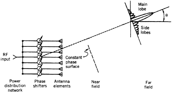
Figure 13.16 Phased array antenna.
After transmission of the preamble, the elevation array is scanned from its lowest to highest angle. This “TO-SCAN” begins slightly below the horizontal and may end as high as 32 deg, although an upper limit of 15 deg is typical of 1996 equipment designs. The scan pauses briefly before beginning the “FRO-SCAN”, back to the lower elevation angle limit [4a].
Azimuth Functions An azimuth function provides lateral guidance in the approach (forward) sector, and a back-azimuth function provides lateral guidance in the departure/missed-approach sector. While the signal formats in the two sectors differ, they are equivalent in principle and are transmitted by similar ground stations. The challenges to accurate azimuth guidance are the low coverage required over the runway and the suppression of interfering reflections from lateral structures (e.g., large hangars). A lateral-pattern beam width of 2 deg is generally satisfactory for runways less than 8,000 ft long; longer runways typically require a 1-deg major lobe, Figure 13.14a. The electrical and physical size relationships of the aperture are the same as those for elevation arrays because the transmission frequency is the same. Because the lateral pattern's side lobes are reflected from structures at wide angles, suppression of the side lobes is less stringent than for the elevation array. Thus, typical side lobes near the major lobe are attenuated 25 dB or more relative to the major lobe. The vertical pattern of the azimuth array is a fan, shaped at lower angles to reduce the amplitude of reflections from the ground and at higher angles to suppress reflections from overflying aircraft.
After transmission of an approach-azimuth or back-azimuth preamble, the azimuth-phased array is scanned clockwise (seen from above) from minimum to maximum pointing angle (e.g., from −40 deg through zero (on center line) to +40 deg). This 80-deg sector is the TO-SCAN limit for back-azimuth, although one version of the approach azimuth can provide a sector of 120 deg [4a]. The scan pauses briefly before beginning the FRO-SCAN back to the minimum azimuth angle.
13.6.3 The Data Functions
Like the angle-function transmissions, the data-word transmissions begin with a preamble that contains an identification code for a “basic” or an “auxiliary” data word. Following the preamble, predefined items of data are transmitted from the azimuth preamble antenna for the allowable time period, using the same DPSK coding scheme as the preamble. The differential encoding provides good resistance to multipath interference, since decoding either the direct or reflected signal yields the same information, (i.e., change = 1, no change = 0).
Basic-Data Words The eight basic-data words contain information about the MLS ground station that is needed for proper operation of the MLS receiver [4a]. Each word contains 26 bits of information plus 2 parity bits. Included in these words are the facility identifier, proportional-guidance limits, minimum glide-path angle, runway length, and so on. All MLS installations must transmit all eight basic-data words.
Auxiliary-Data Words In contrast, the number of auxiliary-data words is expandable to fit local needs, and the amount of data transmitted is limited only by the excess time available in the signal format [4a]. Each word contains 57 information bits plus 7 parity bits. The auxiliary-data words are demodulated within the MLS receiver and output directly to an avionic unit (e.g., a display) or to a data bus. If the addresses of on-board avionics boxes were standardized, the first eight information bits of the word could be the address of the receiving avionics. The remaining bits may include information ranging from weather data to waypoint coordinates for a particular area navigation (RNAV) procedure associated with this runway [18b].
13.6.4 Aircraft Antennas and Receivers
A large aircraft (e.g., B-747) may have one antenna above the cockpit area for forward coverage and one on the fuselage below the tail for coverage to the rear. The azimuth signal format provides a time period for the receiver to select the antenna with the stronger signal. Also, microwave horns are provided behind the nose radome in some installations (e.g., on the USAF C-130) for the final approach. Smaller aircraft may achieve the required ±70 deg forward lateral coverage with only a single antenna typically above the cockpit. The body-mounted antennas are stubs about 0.6-in. high or, on high-performance aircraft, a flush-mounted slot. Generally, the MLS receiver has no RF amplification; signals enter the mixer through a fixed filter that covers the MLS band. After the IF, the preambles and data words are demodulated in a phase-locked loop that has dynamics selected in consideration of the desired bit-error rate and signal-acquisition time. The receiver decodes the basic-data words for internal use and passes the auxiliary-data words through to the avionics data bus. The video envelopes resulting from the TO-FRO passages of the scanning beams are processed in another path to measure the elapsed time between beam passages and to validate envelope width and amplitude. The consistency of these continuous validation checks increments a confidence counter so that the receiver can maintain track in the presence of momentary noise spikes or multipath signals. However, a persistent signal of greater amplitude than the signal being tracked will decrement the confidence counter and cause the receiver to drop the current track and acquire the larger signal after the confidence is zero. In general, MLS receiver designs are centered on a microprocessor. For Category II and III operations, dual or triplicated receiver installations are required (Section 13.2).
13.6.5 Mobile MLS
The U.S. military have devloped a mobile MLS (MMLS) that is transported by a three-man team and installed within 30 minutes each for the azimuth-DME/P or elevation station on runways up to 12.000 ft long [19]. Favorable initial operational test results were achieved in 1993, and production systems were tested in 1995 (Figure 13.17).
The accuracy specifications for the MMLS are based on Category I and II ILS requirements rather than on the MLS accuracy (i.e.. Category III) standard; however, the radiated signals conform to the MLS signal format. These relaxed accuracy requirements were chosen to allow smaller scanning antennas (with wider beam widths) than would be typical of permanent installations. Although antenna aperture has been reduced for lighter weight, the MMLS performance meets MLS standards except at heights below 100 ft.
13.6.6 Precision DME (DME/P)
A precise L-band distance measuring equipment (DME) (±100 ft at runway threshold, 95%) was developed in parallel with the MLS to improve range accuracy when using MLS to calculate the three-dimensional position of the aircraft with respect to the runway (RNAV mode) [4a]. (For a description of the conventional DME, see Section 4.4.6.) The transponder and interrogator designs for DME/P are fully interoperable with conventional DME (DME/N) such that reception of the DME/P signal with a DME/N receiver improves accuracy but does not realize full performance.

Figure 13.17 View up the glide path of a Mobile MLS at the Farnborough Air Show, 1994 (courtesy, Textron Defense Systems).
Obtaining this accuracy improvement requires a faster rise-time pulse to increase accuracy which causes a wider bandwidth. It reduces the radiated transponder power and the power introduced in adjacent L-band channels [4a]. These trade-offs resulted in specifying two modes of operation—an initial approach (IA) mode using the Gaussian pulse shape of DME/N and a lower-power final approach (FA) mode using a composite pulse with a shorter rise-time, an earlier thresholding point, and the standard Gaussian decay time [20]. Thus, the DME/P operates in the IA mode from the MLS outer coverage boundary to 8 nmi from the DME/P antenna, where the interrogator begins changing the pulse-spacing code in order to complete the transition to FA mode by the 7-nmi point.
Typically, the DME/P transponder is located with the MLS approach azimuth station but operates autonomously on the paired frequencies also used with the ILS (Section 13.5.2). Civil DME receivers are standardized by ARINC [32a].
13.7 SATELLITE LANDING SYSTEMS
Even before the global positioning system (GPS) (Chapter 5) was declared operational by the United States in 1993, efforts had been underway to use it for approach and landing. Later efforts involved the Russian GLONASS (Section 5.6) and may result in the combination of GPS Glonass, and other satellites into a Global Navigation Satellite System (GNSS, Section 5.7).
An operational concept called Special Category I Precision Approach Operations Using DGPS, based on the differential GPS (DGPS) technique (Chapter 5.5.9), was developed, tested, and certified for specific airports (Sections 5.5.9 and 5.5.10, and Table 5.7). The test results of the DGPS have been very promising (Refs. [66–68] of Chapter 5). However, the unique requirements of the approach and landing phase with regard to accuracy, integrity, and availability (Section 5.7.1) have led to the development of additional GPS augmentation methods, which are discussed in the next section.
13.7.1 Augmentation Concepts
The basic GPS, without differential corrections, cannot be the primary means of navigation for precision approach and landing operations because of the following limitations:
- Accuracy. The nominal vertical error is ±150 meters, compared to requirements of about ±8 meters for Category I, ±4 meters for Category II, and ±1.3 meters for Category III (Section 13.5.2, Table 13.3).
- Integrity. The GPS design lacks a monitoring system which can provide timely warnings of guidance-data faults within 10 sec for Category I, or less than 2 sec for Category III.
- Availability. The number of satellites in view in certain time periods may not be adequate.
For nonprecision and Category I precision approaches, the above limitations are expected to be mitigated by the FAA's Wide Area Augmentation System (WAAS, Section 5.7.3), which was under development in 1996. WAAS may be supplemented with local differential GPS (LDGPS) stations located near runways. Specifically, the WAAS will address the above three limitations by providing (1) wide area differential GPS (WADGPS) error corrections, (2) a ground integrity broadcast (GIB), and (3) a GPS-ranging function from three or four geostationary satellites providing additional availability or reliability (Ref. [69] of Chapter 5 and [5f] of Chapter 13]. The details of the WAAS are described in Chapter 5.7.3.
To support Category II and III landing operations, the additional requirement for accuracy and monitor-response times can be achieved with a differential GPS reference station and a high-integrity ground-to-air data-link located near the landing runway, constituting a local differential GPS (LDGPS) configuration (Chapter 5.5.9). LDGPS operation leads to nearly complete cancellation of errors due to satellite ephemerides, clock offset, selective availability, and tropospheric/ionospheric propagation, leaving mainly those errors due to multipath-signal interference and receiver noise. The runway reference station (with appropriate monitoring) can supply integrity warnings within the required response time of 1 to 2 sec. Additional availability augmentation may be provided by the WAAS, by a precise time standard on-board the aircraft, and by pseudolites (Chapter 5.7.1) located along the final-approach path or on the airport. In 1996, the U.S. FAA was investigating the feasibility of Category II and III DGPS operations [5f].
13.7.2 Position Solutions
In 1996, GPS receivers were capable of about ten solutions per second, which is sufficient for coupled flight. The accuracy of the SPS code solution without augmentation is satisfactory for nonprecision approaches. The code solution is improved by integrating the Doppler shift of the carrier to obtain a velocity component for smoothing the position measurements and for removing latency effects. Satisfactory auto-land performance has been demonstrated using a velocity-smoothed, code-tracking, differential solution [21]. Carrier phase-tracking differential techniques (Chapter 5.5.9) have also been demonstrated in real time to provide even higher accuracies [22]. This kinematic technique results in a position solution with much lower noise content than code-tracking solutions. Also, good error-canceling properties contribute to the attractiveness of this method. One disadvantage of carrier-phase tracking is that the receiver must accurately determine the range to the satellite in terms of the specific cycle of the carrier frequency. Resolving this integer-wavelength ambiguity for each satellite and guarding against cycle slips requires special techniques (Section 5.5.9 and [23]). Some pseudolite architectures (Section 5.7.4) favor this type of solution, since the high pseudorange rates generated by the aircraft on final approach are a significant aid to cycle ambiguity resolution [24].
13.7.3 Research Issues
Data Latency Delays of two seconds are intolerable during Category III landings. The need for differential corrections to be radioed from a ground station and the on-board processing may delay the position solution for several seconds before it is available to the pilot and flight-control system. Delays can be reduced in the ground computations, in the on-board computations, in the receiver design (e.g.. the Doppler shift of the carrier can measure the velocity vector of the aircraft during the latency period) or by mixing satellite and inertial data. A state-estimator (e.g., a Kaiman filter) can combine the aged position data with the velocity history of the aircraft to provide an accurate estimate of the aircraft's current position.
RF Interference The low level of power received from the spacecraft makes the satellite-based landing system more susceptible to RF interference and receiver noise than has been experienced with the ILS and MLS. In 1996, these effects were under intensive investigation.
Multipath Effects Satellite-signal reflections from terrain or ground objects to the aircraft antenna are small, for air-carrier aircraft, but reflected-signals at the differential stations are larger. Siting criteria, analogous to the airport critical areas developed for ILS and MLS, are likely to be required to ensure integrity.
13.8 CARRIER-LANDING SYSTEMS
13.8.1 Description of the Problem
Aircraft are operated from large aircraft carriers, of which there are about 20 worldwide. Each carrier stores fewer than 100 aircraft and helicopters. Helicopters and vertical-takeoff-and-landing (VTOL) aircraft are operated from smaller ships, of which there are about 300 worldwide. There are approximately 1000 carrier-compatible aircraft in the world, about 2000 naval helicopters and about 250 VTOL aircraft (in 1996, AV8 “jump-jets”) [30].
The typical aircraft carrier landing deck is 600 ft long by 100 ft wide (Figure 13.18). The mean touchdown point is 180 ft forward of the runway threshold at the center of the arresting cable area, which is about 120 ft long by 75 ft wide. Two or three cables are stretched across the deck forward of this point and two or three aft; they are spaced about 40 ft apart. Jet aircraft approach the carrier deck at airspeeds up to 125 knots; their speed relative to the deck is lower due to the “wind-over-deck,” which is normally about 30 knots. The approach path, often called the glide slope, is in the vertical plane containing the runway centerline and is inclined 3.5 deg relative to the sea at the touchdown point (4 deg relative to the moving flight deck) [25]. Aircraft cross the threshold at a mean hook-to-ramp clearance of 11 ft and touch down about 1 sec later without flaring out, at descent rates of 10 to 13 ft/sec. One aircraft may be landed per minute by an automatic landing system; as many as two per minute are landed in VFR weather. The ship's deck “heaves” vertically with a standard deviation of 4 to 5 ft, rolls with a standard deviation of 2.3 deg to 5 deg, pitches with a standard deviation of 1 deg, and yaws with a standard deviation of 1.8 deg during an aircraft approach [25]. The frequency spectra of ship motions are discussed and their relative phasing is shown in [25]. A 1-ft heave causes a 1-ft change in threshold clearance and a 14-ft change in the touchdown point. A 1 deg-pitch causes a 9-ft change in threshold clearance and an 80-ft change in the touchdown point. Ship motions affect impact velocity at touchdown. A night landing on a carrier deck is the most difficult and dangerous task in aviation.
The prevailing wind and forward motion cause a wind-over-deck between 20 and 40 knots; the ship is steered to place the relative wind along the canted flight deck. Forward motion of the ship aids the pilot by reducing landing speed relative to the deck, but it causes a turbulent-air wake which interferes with the landing. The air wake may be divided into the following components [25]:
- Steady-state wake caused by the relative wind over the ship's deck and around the superstructure (“island”), which causes a “burble” at the threshold and along the glide path. The vertical and horizontal components of the steady-state wake for a Forrestal-class carrier are shown in [25].
- Wake perturbations, due to the ship's angular motions and heave, causing fluctuations with standard deviations of 2 ft/sec (horizontal) and 4 ft/sec (vertical) about the steady state wake. These become negligible 2000 ft aft of the threshold.
Aircraft are stacked in holding patterns 8 to 12 nmi astern at altitudes from 4000 to 40,000 ft. They are vectored onto the glide path by carrier air traffic control (CATC) using voice radio and the approach control radar until they are within the coverage of the SPN-41 and the SPN-46 instrument landing systems. Pilots are released from the holding pattern to the glide path and may follow cockpit display “needles” or may couple the autopilot to the Automatic Carrier Landing System (ACLS). Carrier pilots are also provided cues by a Fresnel-lens optical system nicknamed the “meatball,” Figure 13.19.
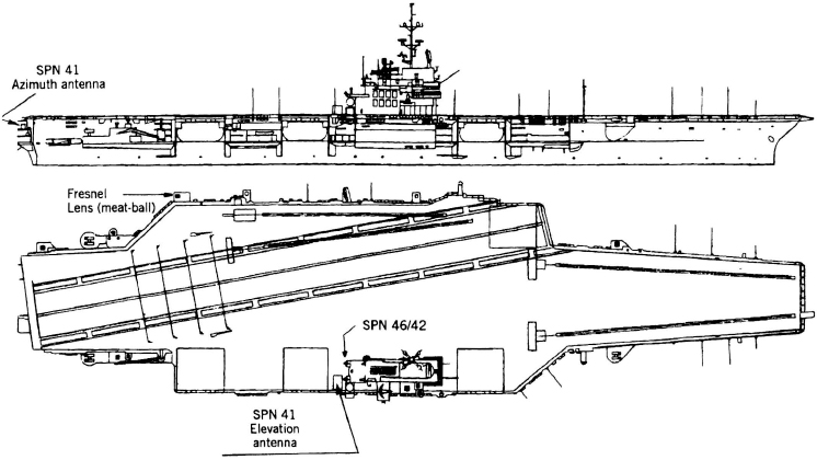
Figure 13.18 Canted-deck aircraft carrier showing installation of SPN-46/42, SPN-41, and FLOLS (courtesy of U.S. Naval Air Engineering Center).
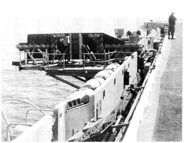
Figure 13.19 Fresnel-lens optical landing aid (courtesy, U.S. Navel Air Engineering Center).
An aircraft executing a missed approach from low altitude is called a bolter. Bolters fly to a Tacan-defined holding point that moves with the aircraft carrier.
The ACLS is capable of landing an aircraft “hands off,” giving the U.S. Navy an operational capability in zero-zero visibility conditions. In 1996, ACLS could fly an F-18 down the glide path more accurately than an average F-18 pilot [28]. However, peacetime air operations were routinely discontinued when visibility fell below ![]() to
to ![]() nmi or ceilings dropped below 200 ft. Carrier commanders were reluctant to depend on the ACLS in zero-zero visibility, except in emergencies or during hostilities.
nmi or ceilings dropped below 200 ft. Carrier commanders were reluctant to depend on the ACLS in zero-zero visibility, except in emergencies or during hostilities.
13.8.2 Optical Landing Aids
In the early days of aircraft carriers, the landing signal officer (LSO) guided the pilot using a paddle in each hand. The LSO signalled with colored lights and voice radio. Mirrors fixed to the deck were used during the 1950s to assist pilots in following the glide path by projecting an image of a light along the path.
Because of deck rotation, the aid was gyrostabilized. In 1968, mirrors began to be replaced by a vertical array of five Fresnel lenses (Figure 13.19) showing the pilot a yellow spot (“meatball”) that moves vertically relative to a lighted green horizontal reference bar. The array is called the “Fresnel lens optical landing system (FLOLS) [29]. The beamwidth of each lens is about 5 mrad. Because the five lenses are spaced about 3 ft apart, adjacent beams overlap beyond 1000 ft, so pilots cannot easily estimate their displacement above or below the glide path beyond 2000 to 4000 ft. The meatball gives only vertical cues.
The optical axis of the system is servoed to remove ship's pitch and roll but not heave, although “compensated meatball” methods have been proposed which correct for all three [25]. Lens pointing angles would be adjusted according to a quadratic function of heave in much the same way as the angle data from the radar-controlled ACLS is compensated (Section 13.8.3). This compensation has not been implemented because the “meatball” is often shared by two aircraft on final approach simultaneously.
13.8.3 Electronic Landing Aids
Two electronic instrument landing systems are found on all large U.S. aircraft carriers. The ACLS involves two identical conically scanned Ka-band radars (SPN-46 or SPN-42) set aft of the island about 125 and 135 ft above the water line. They can track two aircraft simultaneously and, if desired, can uplink guidance signals to aircraft autopilots. An independent sensor (the SPN-41) monitors the approach. SPN-41 consists of a Ku-band transmitter and an airborne receiver/processor. The receiver measures angular displacements from the glide path.
Automatic Carrier Landing System Both SPN-42 and its successor, SPN-46, are tracking-radar systems differing primarily in the antenna. Figure 13.20 shows one of the dual-frequency SPN-46 antennas. The SPN-42 was retrofitted with a small X-band parabola when aircraft beacons were added to eliminate errors caused by spatial “wandering” of the skin echo. Both radars radiate short pulses at Ka-band and receive replies from an X-band beacon (APN-202 or APN-154) as well as Ka-band skin-echoes. Radar pulses, modulated by the conically-scanning beam, are detected by the aircraft beacon receiver and data are returned to the radar in the form of the arrival time and power of a pulse from the X-band beacon's magnetron. Range and angle estimates are formed aboard ship by conventional processing of the X-band signals. Angular accuracy is primarily a function of the conically scanned Ka-band beam pattern (the X-band receiving beam is relatively broad). Errors in transferring uplink pulse height to the X-band beacon tend to cancel in the radar tracking processor.
Data measured by the radar/beacon system are digitized and delivered to a central ACLS computer which computes commands intended for the autopilot of the aircraft in track suitable for flying the aircraft down the glide path. These data are communicated to the aircraft via a UHF “Link 4” data channel [26]. The pilot has the option of coupling the autopilot to the ACLS, flying the aircraft from “needles” controlled by ACLS data, or being “talked down” by a shipboard controller. A manual carrier landing with ACLS resembles a land-based ground-controlled approach.
Figure 13.20 SPN-46 antenna (courtesy, U.S. Navy).
SPN-41 Independent Landing Monitor This system consists of a single Ku-band transmitter switched between separate azimuth and elevation antennas. Although driven synchronously, the horizontally and vertically scanning fan-beam antennas are separate units. A small rotating parabolic reflector provides a shaped vertical fan beam that scans the azimuth sector ±20 deg; at the end of the scan the transmitter is switched to the vertically scanning fan-beam formed by a horn antenna that mechanically oscillates at the end of a short torsion bar. The aircraft receiver converts pairs of short Ku-band transmitter pulses to IF and video. The pair spacing identifies the azimuth or elevation beam, and the spacing between pairs indicates its pointing angle. Airborne processing uses amplitude information in estimating aircraft azimuth and elevation angles relative to the desired glide path, which then drives localizer and glide-slope needles in the aircraft. Land-based SPN-41 was used for landing Space Shuttles in the 1980s and 1990s.
Figure 13.18 shows the locations of the SPN-41 azimuth and elevation antennas aboard ship. The SPN-41 is shared by all aircraft in the landing sequence. Antennas are stabilized in roll and pitch but are not compensated for heave. Since it conveys no range information and has no data link, the SPN-41 cannot be used as an ACLS. Common practice is to use SPN-41 signals at relatively long range (20 to 30 nmi) for ACLS acquisition guidance. It also serves as a monitor of SPN-42/46 angle information until the aircraft is within 12 sec of touchdown.
SPN-35 Precision Approach Radar (PAR) A few fixed-wing aircraft carriers carry the SPN-35 as a backup to the SPN-46 or SPN-42. However, just as in commercial avaiation, PARs are seldom used because they depend on a trained operator.
In 1996, there were more than 20 LHA, LHD, and LPH assault ships that carried only SPN-43 (approach surveillance) and SPN-35 PAR for low-visibility landings of helicopters and VTOL aircraft such as the AV-8 Harrier. Nonprecision low-visibility landings may be accomplished with Tacan (Chapter 4).
13.9 FUTURE TRENDS
13.9.1 Pilot Aids
In 1996, several technologies were being pursued to reduce pilot work load during approach and landing or to improve the pilot's ability to monitor an automatic landing.
Enhanced vision systems, such as active millimeter-wave radar (MMWR) and passive forward-looking infrared (FLIR) detectors, can create an artificial image of the runway and project it on a head-up display. MMWR developments have focussed on 35 and 94 GHz where RF transmission “windows” exist in the atmosphere. The higher frequency (3-mm wavelength) gives better resolution, but the lower frequency (9-mm wavelength) requires less power to penetrate rain. Even at these short wavelengths, physical constraints limit the beam width to about 0.25 deg, which does not provide adequate runway resolution at the shallow elevation angles encountered during the landing maneuver [4f]. Passive infrared systems with wavelengths near 10 nm (10−5 mm) have adequate resolution and reasonable fog penetration characteristics, but heat sources may be required along the runway to improve the contrast of the runway against background terrain. The minimum range of a laser radar (200 ft in 1996) may deny its use for taxi guidance.
Infrared cameras (FLIR) combined with head-up displays (HUD, Chapter 15) are found in some navy aircraft. FLIRs have been tested on aircraft carriers for monitoring operations in clear weather at night but IR energy suffers almost the same absorption as visible light in fog and rain.
Figure 13.21 shows a 4 × 4 element 94 GHz focal-plane array of antenna/detector elements that was fabricated photolithographically on a wafer of GaAs (about 1-in. square) [28]. If replication of such a tile were inexpensive, 94 visual GHz cameras and focal plane array radars might enter service as landing aids.
The HUD, which was developed by the military services to aid a single pilot in transitioning to visual cues, is finding applications on air-carrier aircraft (Chapter 15.3). It projects sensor information (navigation, attitude, and other sensors) and stored runway data onto the windscreen at infinite focus, so that the pilot can see the data and images superimposed on the view through the windshield. In 1996, European and American authorities had certified many aircraft for Category IIIA operations and most glass-cockpit models of Boeing, Douglas, and Airbus aircraft for Category 1IIB operations. These authorities have allowed a HUD and a fail-passive autopilot to substitute for a fail-operational autopilot.
Figure 13.21 A 4 × 4 element 94 GHz focal plane array (courtesy, U.S. Naval Research Laboratory and Westinghouse Corporation).
13.9.2 Satellite Landing Aids
There is a need for low-cost, nonprecision and Category I procedures at low-density airports in the industrialized countries and in underdeveloped countries that have poor highway and railroad systems and are therefore dependent on air travel. Satellite-navigation systems are likely to be the solution. Similarly military needs for tactical approach guidance systems (including landing on ships) will probably be satisfied by differential or relative satellite techniques (Section 13.7). For lower-visibility landing, an independent monitor is required.
During the period of transition from ground-based to satellite-based guidance, multi-function airborne receivers, capable of processing ILS, MLS, and GPS guidance signals, will be used in civil and military aviation. An ARINC characteristic for such a multimode receiver was in preparation in 1996. Two technologies that will aid the application of satellite navigation to precision approach operations are lower-cost inertial devices and lower-cost precision (atomic) clocks.
13.9.3 Airport Surface Navigation
The use of differential satellite-based systems for guidance and surveillance of rollout, taxi, and departure operations under low-visibility conditions will be widespread and will extend to vehicles other than aircraft (e.g., fuel trucks, police and emergency vehicles). The combination of LDGPS (Section 5.5.9) and pseudolites (Section 5.7.5) is likely to offer a solution to the airport surface navigation and surveillance problem.
13.9.4 Carrier Landing
The challenging problem of all-weather recovery of large (up to 65,000 lb) aircraft aboard a floating platform less than 1000 ft long will lead to new guidance systems. The combination of relative GPS (Chapter 5), a data link, and aircraft and ship attitude sensors could provide the basis of a new ACLS. In the difficult environment of carrier landings, an independent monitor will be needed, perhaps a descendant of SPN-41 or SPN-46.
PROBLEMS
13.1. A particular aircraft can deviate ±85ft laterally from the runway center line without leaving the hard surface. Assuming the errors are normally distributed, calculate the allowable lateral deviation (1-sigma) if the lateral performance requirement for the auto-land system states that the risk (probability) of touchdown off the runway is not to exceed 3 × 10⁻⁸.

Problem 13.1 Accuracy-allocation tree.
The accuracy-allocation tree below allocates this accuracy to each error source.
13.2. Discuss the factors associated with raising the operational category for landing on a particular runway.
13.3. What precision in terms of linear measure is needed for positioning a large transport aircraft at the approach threshold for a successful landing with visibility of 1200 ft?
13.4. What factors can degrade the guidance quality of an ILS signal?
13.5. What would prevent a DME, associated with an ILS serving a specific runway, from being used for an approach to a different runway?
13.6. Compare the value of approach lights versus runway lights to a pilot who is conducting an approach to Category II weather minimums.
13.7. What justifies the expectation that ILS marker beacons will find less use after 1997?
13.8. Discuss whether a building of a given size will be a more efficient reflector (scatterer) of glide-slope or localizer signals.
13.9. Suppose that an airport is adding a new runway that will be much closer to existing hangers than the existing runway. Assume that all physical obstruction criteria will be met. With respect to the radio guidance signals, identify the factors that must be considered when assessing the suitability of the new runway.
13.10. Considering all GPS error sources, what is the key issue in siting ground reference and monitor stations for a pseudorange-based, local area, DGPS approach and landing system?
13.11. A GPS antenna is mounted on a pole 2 meters above the ground. Signals are received from a satellite at a low-elevation angle. The GPS antenna will receive both the direct signal and one multipath signal from the ground below the antenna. Assume perfectly flat ground below the antenna. The frequency of the GPS signal is 1575.42 MHz. Figure 13.11 shows the (actual) satellite elevation angle during a 10-sec observation interval.