14 Air Traffic Management
14.1 INTRODUCTION
The purpose of air traffic management (ATM) is safe, efficient, and expeditious movement of aircraft in the airspace. It comprises two principal processes: air traffic control and traffic flow management. Air traffic control (ATC) is the tactical safety separation service whose function it is to prevent collisions between aircraft and between aircraft, terrain and obstructions. Traffic flow management (TFM) is the process that allocates traffic flows to scarce capacity resources (e.g., it meters arrival at capacity constrained airports).
The principal elements of the ATM process are airspace; air navigation facilities, equipment, and services; airports and landing areas; aeronautical charts, information, and services; rules, regulations, and procedures; technical information; and work force, including flight crews, air traffic controllers, traffic managers, and facilities technicians [37, 18]. This chapter describes these elements of the ATM process and explains how they interact to fulfill its purpose.
14.1.1 Services Provided to Aircraft Operators
A principal service provided by ATM is separation assurance for the prevention of collisions between aircraft and to prevent aircraft collisions with terrain and obstructions. Traffic flow management services are designed to meter traffic to taxed capacity resources, both to assure that unsafe levels of traffic congestion do not develop and to distribute the associated movement delays equitably among system users.
Relevant aeronautical information is provided both in the form of charts and publications and as current (real-time) information communicated to the user prior to and during flight. The real-time information provided includes weather observations and forecasts, traffic congestion conditions and delays, status of air navigation facilities and airports, and the positions and movement intentions of other aircraft in the vicinity. The final principal service is search and rescue, that is, notification of appropriate organizations regarding aircraft in need of search and rescue assistance and support of these organizations during the ensuing operations.
Navigation generally is the responsibility of the aircraft operator. Nonetheless, air traffic controllers assist lost and distressed aircraft in determining their positions and navigating to their destinations.
14.1.2 Government Responsibilities
Within the United States, the Federal Aviation Administration (FAA) is responsible for establishing rules and regulations allocating airspace to various uses and regulating those uses; for establishing and operating air navigation facilities; for ensuring the publication of aeronautical charts and information necessary for the safe and efficient movement of aircraft; and for establishing the rules, regulations, and procedures governing air traffic control and traffic flow management. The agency is also responsible for establishing minimum standards regarding the design, construction, certification, and maintenance of air-craft and airports as well as for certifying flight crews [4]. The United States has a common system for ATM in the sense that the same practices apply to civil and military users and both the FAA and Department of Defense (DOD) provide ATM services to both civil and military users. In many areas of the world, most of the airspace is devoted to military operations for which military authorities have jurisdiction; civil aviation authorities provide services to civil users in limited corridors set aside for that purpose.
Standardization of air traffic management practices internationally is the responsibility of the International Civil Aviation Organization (ICAO), which is affiliated with the United Nations and located in Montreal, Quebec, Canada. Procedures for aircraft operation and the provision of ATM services are standardized to the extent necessary to ensure regularity worldwide. In addition, appropriate technical standards for aircraft, air navigation facilities, aeronautical information and charts, and airports are established. ICAO does not provide ATM services directly to operators.
Countries align their procedures and equipment with ICAO standards so that there is safe and efficient operation of international aircraft within their borders. As a result, ATM practices and procedures around the world have few differences. Some regions have less developed ground facility infrastructures than others and the efficiency of aircraft operations suffers as a result (Section 1.7). Increased use of satellite-based services for communication, navigation and surveillance will foster better ATM services worldwide.
14.2 FLIGHT RULES AND AIRSPACE ORGANIZATION
14.2.1 Visual and Instrument Flight Rules
Aircraft in flight operate in accordance with one of two sets of rules, visual flight rules or instrument flight rules. Visual flight rules (VFR) operators are responsible for avoiding collisions with obstacles, terrain and other aircraft by visually observing these hazards and maintaining visual separations. Therefore, visibility conditions must meet prescribed minimums and the aircraft must remain clear of clouds. In much of U.S. airspace, VFR operators are not required to contact ATM authorities and are not subject to their directions. VFR flights usually involve small aircraft operated for personal or business purposes. Navigation may be by visual reference to the ground and aircraft attitude control may be based solely on the natural horizon visible through the windscreen of the aircraft.
Flight crews following instrument flight rules (IFR) must be capable of navigating and controlling the aircraft without reference to an outside visual scene. In controlled airspace, the crew must operate in accordance with instructions received from ATM authorities, and these authorities are responsible for separating the aircraft from all other IFR aircraft. Aircraft operating IFR must be equipped with appropriate attitude indicators, radios and other navigation equipment not required on VFR aircraft. Further, the flight crew requires additional training and experience to qualify for the necessary instrument rating. All aircraft operators holding Air Carrier Operating Certificates are required to follow instrument flight rules [6].
14.2.2 Altimetry
In order to understand airspace organization and navigation practices in the ATM community, it is necessary to know how altitude measurements are made in aircraft [7]. The barometric altimeter (Chapter 8) measures the static air pressure outside the aircraft and converts this pressure to an altitude, in feet, based on a standard model of the atmosphere adopted by ICAO [60]. According to the model, atmospheric pressure and temperature at mean sea level are 29.92 in. of mercury (1013.2 hectopascals) and 15.0°C, respectively. The temperature lapse rate in the model is 2.04°C per 1000 ft from sea level to 35,000 ft above mean sea level, after which the temperature is constant at −56.5°C.
The aircraft barometric altimeter permits the flight crew to set the reference pressure against which the outside atmospheric pressure is measured. If the reference pressure were adjusted to the actual pressure at mean sea level, and the temperature lapse rate matched the ICAO standard model, the altimeter would indicate true altitude above mean sea level. Unfortunately, due to the varying characteristics and movements of air masses, the pressure at mean sea level varies around the world, and these pressures may not be representative of air masses over land areas. Hence, altimeters are installed in ground stations (e.g., airports and flight service stations) and in the USA the setting is adjusted so that the altimeter indicates the true altitude above mean sea level of the station. A flight crew operating below 18,000 ft above mean sea level uses the setting provided by a station located along the route of flight within 100 nmi of its position. The resulting altimeter reading displayed to the crew is termed the indicated altitude and is a good estimate of the aircraft altitude above mean sea level. Hence, indicated altitude is expressed in feet above mean sea level, which is abbreviated “ft MSL.” Above 18,000 ft MSL, flight crews set their altimeters to 29.92 in. of mercury. The resulting altimeter reading is referred to as the pressure altitude. Pressure altitudes are expressed as flight levels (FLs) in hundreds of feet using three digits. Hence, FL290 represents a pressure altitude of 29.000 ft.
14.2.3 Controlled Airspace
A fundamental construct of the ATM system is the organization of airspace into various categories and the establishment of rules governing aircraft operations within each category. The objective is to provide maximum freedom in public use of the airspace while ensuring the safety and efficiency of flight operations where airspace is heavily used or is required to support special purposes such as military training.
Within airspace regions categorized as controlled, aircraft operating IFR are required to receive separation and other services from ATM authorities. VFR operators are required to accept ATM separation services in some types of controlled airspace. Ground-to-air communications and navigation aids support these services. The following paragraphs describe a few examples of controlled airspace. Additional details are given in the Airman's Information Manual [8].
Class A—Positive Control Area Virtually all of the airspace above the 50 U.S. states from 18,000 to 60,000 ft MSL is designated Class A. All aircraft within Class A airspace must follow instrument flight rules, that is, must file IFR flight plans and operate in accordance with clearances. A clearance is authorization for an aircraft to proceed under conditions specified by the responsible ATM authority. The purpose of Class A is to ensure separation for all aircraft operating in this regime wherein aircraft speeds are high and VFR see-and-avoid techniques are ineffective.
Class B—Terminal Control Areas Class B airspace exists around the nation's busiest airports. The general shape of Class B airspace resembles an upside-down wedding cake centered on the primary airport. The radius increases with altitude so that aircraft remain within the airspace as they descend into or climb away from the airport. All aircraft, whether operating by IFR or VFR, must receive a clearance to enter the airspace and the associated ATM authority is responsible for separating all aircraft. Aircraft at the same altitude are kept at least 3 nmi apart. Aircraft within 3 nmi of one another are separated vertically by at least 1000 ft if both aircraft are IFR, or by at least 500 ft if one aircraft is IFR and the other is VFR. VFR aircraft are required to operate in accordance with visual flight rules including maintaining prescribed distances from clouds. IFR operators have priority over VFR aircraft, and access by VFR operators can be denied if the ATM authority believes VFR operations would compromise safety.
14.2.4 Uncontrolled Airspace
Uncontrolled airspace is airspace that is not designated as controlled. In the United States, most uncontrolled airspace is within 1200 ft of the ground in sparsely traveled areas. ATM authorities will not provide separation services in uncontrolled airspace. IFR operators need not file flight plans and may operate in any visibility conditions. VFR operators below 10,000 ft MSL must have a minimum visibility of one statute mile.
14.2.5 Special Use Airspace
Special use airspace is set aside for unique purposes, notably national security operations. A prohibited area such as the airspace surrounding the White House is closed to aircraft operations at all times. Restricted areas such as military missile ranges are closed to civil traffic when operating and are open at other times. Military operations areas (e.g., for training) will accept IFR traffic if the responsible ATM authority can safely provide separation services. VFR aircraft must exercise extreme caution when operating in active military operations areas.
14.3 AIRWAYS AND PROCEDURES
14.3.1 Victor Airways and Jet Routes
A system of federal airways (highways in the sky) is defined by Parts 71 and 93 of the US Federal Aviation Regulations. As illustrated in Figure 14.1, most of these airways originate and end at VOR stations (Section 4.4.4). A few airways based on nondirectional beacons (Section 4.4.2) are still in use.
From 1200 ft above the surface to 18,000 ft MSL, VOR-based airways are called victor airways and use “V” as a prefix in their identifiers (e.g. V51). From 18.000 ft MSL to 45,000 ft MSL, all federal airways are based on VORs and are referred to as jet routes. The prefix of the identifiers is “J” (e.g. J64).
Changeover points (COPs) are defined along airways to indicate where the pilot should adjust the navigation receiver to obtain course guidance from the facility (e.g. VOR) ahead instead of the one behind. The COP is normally at the midpoint between facilities but may be elsewhere if required due to radio frequency interference, facility siting limitations, or other effects. If a COP is not at the midpoint of the airway, its position is shown on aeronautical charts.
Every VOR is designated either as a terminal VOR or as a low- or high-altitude en-route VOR. Terminal VORs are intended for use in the local area, for example, to support instrument approach and departure procedures. They are usable only at ranges less than 25 nmi and may not be used for en-route navigation. Low-altitude en-route VORs have service volumes extending up to 40 nmi from the facility and are used at and below 18,000 ft MSL for navigation on victor airways. High-altitude VORs support navigation on jet routes; their service volumes may extend 200 nmi from the facility. Service volumes of VORs are controlled as described above in order to limit frequency interference effects among adjacent ground stations.
Airway widths are determined by navigation system performance, taking into account errors in the ground station equipment, errors in the aircraft receiver and display system, and flight technical error. Flight technical error is the lateral displacement error of the aircraft from the intended track given the course deviation error signal generated by the navigation system. For the manually piloted aircraft, it represents the pilot's ability to stay on course based on the displayed cross-track error. Typical 2-standard-deviation allowances for VOR/DME in the en-route environment are 1.9 deg for the VOR ground equipment and 3.0 deg for the airborne receiver. DME ground station error allowance is 0.1 nmi with the avionics allowed 0.5 nmi or 3% of range, whichever is greater. Under the assumption that the aircraft is piloted manually, the cross-track component of the flight technical error allowance is 2.0 nmi. The total error in positioning the aircraft on the intended route is derived by root-sum-squaring these errors, treated as independent [9].

Figure 14.1. Aeronautical chart showing victor airways.
As illustrated by the example in Figure 14.2a, VOR airways are divided into primary and secondary obstacle clearance areas. The primary obstacle clearance area is 4 nmi either side of the route centerline except that the area expands along system accuracy lines drawn at a 4.5-deg angle either side of the center line when the COP is more than 51 nmi from one of the facilities [10]. The secondary obstacle clearance area extends 2 nmi either side of the primary area except where the COP is more than 51 nmi from the facility, in which case the secondary area is bounded by a 6.7-deg angle drawn either side of the center line.

Figure 14.2. Primary and secondary obstacle clearance areas for an airway.
Along each airway segment between facilities, a minimum en-route altitude (MEA) is established to ensure adequate clearance of obstacles and terrain in both the primary and secondary obstacle clearance areas. In nonmountainous areas, obstacle clearance in the primary area must be at least 1000 ft. The secondary area is raised above and slopes upward and outward from the primary area, as shown in Figure 14.2b. No obstacle may protrude above the secondary area. The MEA is set high enough to ensure adequate navigation signal reception and air-to-ground communications coverage. Aircraft operating IFR are assigned altitudes at or above the MEA.
14.3.2 Random Routes
Many aircraft have area navigation (RNAV) capability, also known as random route navigation. The on-board navigation system determines the position of the aircraft and a navigation computer, often embedded in the flight management system (see Section 14.5.7), carries out the necessary course computations for reaching the next waypoint according to the principles described in Chapter 2. (A waypoint is simply a geographically fixed position identified by its latitude and longitude.) Aircraft with RNAV capability are not constrained to travel directly toward or away from ground-based VORs as are aircraft flying along airways. Position determination may be based on station-referenced navigation signals such as VOR, DME, Loran-C, Omega, and GNSS (Chapters 4 and 5) or a self-contained capability, such as an inertial reference unit (Chapter 7). Random routes generally reduce flight distances between origins and destinations as compared to operation along the associated victor airways and jet routes. In addition, they serve to disperse traffic geographically, thereby reducing traffic congestion and increasing the traffic capacity of the airspace.
Procedures for constructing random routes that meet obstacle clearance requirements for IFR operations are provided in FAA Advisory Circular 90-45 [9]. Routes are defined based on charted waypoints, which are assigned five-letter pronounceable names. Primary and secondary obstacle clearance areas are established around the route center line. Then minimum en-route altitudes (MEAs) are established using the obstacle clearance criteria applied to airways. The lateral dimensions of the obstacle clearance areas depend upon the accuracy of the navigation system used. In the case of VOR/DME, dimensions depend upon the perpendicular distance of the facility from the route center line and the distance along the route from that tangent point (see Figure 14.3).
14.3.3 Separation Standards
There are three dimensions of separation—lateral, longitudinal, and vertical—and three sets of rules for ensuring that adequate separation exists—procedural, radar, and visual. Procedural separation is based on aircraft following preplanned flight trajectories so that all aircraft in the region will be adequately separated. Flight progress and adherence to flight plans are monitored by contrailers based on position reports received from flight crews. In the future, these position reports may be provided by the automatic dependent surveillance function (Section 14.5.3). Lateral and longitudinal separation standards (minimums) are based on the accuracies of the navigation systems in the aircraft. The minimums are lower along routes based on VOR/DME than over oceans, where less accurate inertial reference units (IRUs) and Omega have been the only means for navigation until the introduction of GPS (Section 5.5) on some aircraft. For example, aircraft procedurally separated at the same altitude and speed along the same airway or RNAV route using VOR/DME must be spaced at least 20 nmi apart [11 (Chapter 6)]. In oceanic airspace, aircraft at the same altitude on the same route are commonly separated by 10-min intervals that correspond to about 80 nmi for aircraft traveling at M 0.85 at FL350. Similar results apply to separation minimums for aircraft with crossing flight trajectories and for lateral separation of routes and flight trajectories.

Figure 14.3. Primary and secondary obstacle clearance areas for an RNAV route.
Radar separation standards depend upon the accuracy of the radar position report displayed to the controller and hence the distance of the aircraft from the radar ground station. In the United States, the radar separation standard is 3 nmi in terminal areas when the traffic is within 40 nmi of the radar site and 5 nmi for traffic beyond 40 nmi. In the en-route environment, it is 5 nm below FL600 and 10 nmi above [11, Chapter 5].
Vertical separation is applied by fixed rules for IFR aircraft operating in uncontrolled airspace and for VFR aircraft [8, Chapter 3]. For example, VFR aircraft cruising on magnetic courses between zero and 179 deg, more than 3000 ft above the surface but below 18,000 ft MSL, fly at odd thousands (MSL) plus 500 ft (e.g., at 3500 ft, 5500 ft, and 7500 ft MSL). Opposite direction VFR traffic cruises 1000 ft away (e.g., at 4500 ft, 6500 ft, and 8500 ft MSL). IFR traffic in controlled airspace operates at altitudes or flight levels assigned by ATM. These altitudes are integer thousands of feet (e.g., 4000 ft, 12,000 ft, FL310) with a 1000-ft separation minimum up to and including FL290 and a 2000ft separation standard above FL290. In 1988, ICAO concluded that a 1000-ft vertical separation standard can be established worldwide between FL290 and FL410 without imposing unreasonable technical requirements on aircraft. Planning was initiated at that time to implement the 1000-ft standard in heavily traveled airspace over the North Atlantic by 1996 [21].
Visual separation may be applied to IFR aircraft by a controller who is in communication with at least one of the aircraft and who can see both aircraft and maintain visual separation or at least is advised by one of the pilots that s/he can see the other aircraft and accepts responsibility for maintaining visual separation. Because visual procedures effectively reduce separation standards, they can expedite the flow of traffic and increase both the capacity of the airspace and the flexibility of flight operations. They are commonly used in terminal airspace, for example, in sequencing and spacing arrivals. They have less application in the en-route environment where aircraft relative speeds are high.
14.3.4 Terminal Instrument Procedures
When meteorological conditions permit VFR operations (i.e., visual meteorological conditions, VMC, prevail), flight crews may be able to make transitions from en-route airspace to terminal areas and runways visually. Alternatively, a crew may conduct an instrument approach procedure to guide the aircraft to the runway environment while ensuring safe clearances above terrain and obstacles. The runway environment consists of the runway threshold and approved lighting aids and markings identifiable with the runway (Chapter 13). Similarly, departures in VMC may be conducted visually. When meteorological conditions do not permit the visibility required for VFR, instrument meteorological conditions (IMC) prevail. In IMC, or when elected by the flight crew, departures are conducted in accordance with prescribed instrument departure procedures. Instrument procedures are designed specifically for the associated runway end, and then charted and distributed to the user community [5, 12, 28, 36]. The criteria for designing instrument procedures are provided by TERPS [10].
An instrument approach procedure describes the route the aircraft should follow (the procedure course) and the altitudes to be flown. The route and altitudes are referenced to the navigation aids supporting the procedure, which may include VOR, VOR/DME, TACAN, VORTAC, NDB, Loran-C, IRUs, ILS, the localizer-only portion of ILS, MLS, GNSS, precision approach radar, and airport surveillance radar. Radar serves as a navigation aid when a controller uses the system to monitor the position of an aircraft relative to obstacles, terrain, and the runway and issues heading, speed, and/or altitude instructions to guide aircraft to the runway environment. Instrument approach procedures also state landing minimums, which have two parts—the minimum altitude to which the aircraft can descend without sighting elements of the runway environment and the minimum visibility on the runway surface permitted when conducting the procedure, e.g., visibility required to be at least 1 smi (Chapter 13).
The following description of a simple instrument approach procedure illustrates the essential considerations in their construction [5, 28]. As shown in Figures 14.4 and 14.5, the procedure has four segments. The initial approach segment commences at the initial approach fix (IAF). In Figure 14.4, this segment derives positive course guidance from a VOR ground station. VOR system inaccuracies, including flight technical error, require a primary obstacle clearance area extending 4 nmi on each side of the course and a secondary obstacle clearance area extending laterally 2 nmi on each side of the primary area. If any portion of the segment is more than 51 nmi from the VOR, the obstacle clearance areas must be expanded in accordance with the en-route VOR airway criteria described earlier (Figure 14.2). Along the initial approach segment, the obstacle clearance in the primary area must be at least 1000 ft. In the secondary area, the clearance must be at least 500 ft at the inner edge tapering uniformily to zero at the outer edge.

Figure 14.4. Obstacle clearance surfaces for a precision instrument approach procedure.
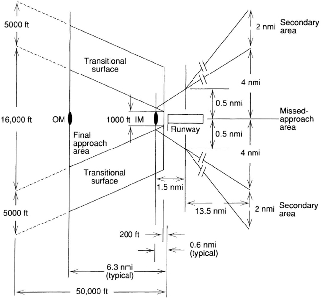
Figure 14.5. The final approach and missed approach areas.
The intermediate segment begins at the intermediate fix (IF) and extends to the final approach fix (FAF). For an ILS approach procedure, the IF is defined by the intersection of the initial approach course and the localizer course. Along the intermediate approach segment, aircraft make speed and configuration changes in preparation for the final approach. The length of the segment is between 5 and 15 nmi, and the obstacle clearance areas have the same widths as the areas of the adjoining segments. The minimum obstacle clearance in the primary area is 500 ft. In the secondary area, 500 ft of clearance must be provided at the inner edge tapering to zero at the outer edge.
The final approach segment shown in Figures 14.4 and 14.5 assumes a Category I ILS installation consisting of localizer and glide-slope stations of Category I quality and outer and inner marker beacons. (See Chapter 13 for detailed descriptions of the ILS equipment.) The outer marker (OM) serves as the FAF and is located at the point where an aircraft at the prescribed altitude at the end of the intermediate approach segment intercepts the glide slope. The length of the final approach course is dictated by the altitude prescribed at the FAF and the glide-slope angle, which is usually 3 deg. The course generally is less than 50,000 ft long.
As shown in Figure 14.5, the width of the final approach area is 1000 ft at a point 200 ft from the threshold and expands uniformly to a width of 16,000 ft at a point 50,000 ft from the beginning of the area. The final approach obstacle clearance surface is an inclined plane which originates at the runway threshold elevation 975 ft down the runway from the glide-slope ground point of intercept and overlies the final approach area. (The glide-slope ground point of intercept is the point on the runway center line at which the straight-line extension of the glide slope intercepts the runway surface.) The slope of the final approach obstacle clearance surface is a function of the glide-slope angle. Transitional surfaces for ILS Category I are inclined planes with a slope of 7 : 1 extending outward and upward from the final approach obstacle clearance surface. The final approach obstacle clearance criterion increases with distance from the runway threshold. (Chapter 13 covers categories II and III).
Aircraft approaching the runway using an ILS procedure may descend to the decision height without visually acquiring the runway environment. If the runway is not acquired at the decision height, the pilot must conduct a missed approach procedure. For Category I ILS approaches, the decision height may be no lower than 200 ft above the touchdown zone. If obstacles protrude through the final approach obstacle clearance surface, either the glide-slope ground point of intercept must be moved farther down the runway until the protrusions disappear, which reduces the usable length of the runway in IMC, or the decision height must be raised for adequate clearance. Raising the decision height reduces the utility of the runway in IMC.
The final portion of the approach procedure is the missed approach segment. It begins at the missed approach point (MAP), which is the point on the final approach course where the height of the glide slope above the touchdown zone equals the decision height. The inner marker (IM) generally is located near the MAP. The missed approach segment extends to a point or fix where either initial approach or en-route obstacle clearance is achieved. A straight missed approach course is 15 nmi long, and the missed approach area is 8 nmi wide at the end. Obstacle clearance criteria ensure that an aircraft in the missed approach area climbing with a gradient of at least 150 ft/nmi from the MAP will not collide with an obstacle. In addition, obstacles may not penetrate the secondary areas that slope upward at 12:1 from the missed approach area.
14.3.5 Standard Instrument Departures and Arrivals
Standard instrument departures (SIDs) and standard terminal arrival routes (STARs) are published IFR procedures for transitioning between terminal and en-route airspace. Their purpose is to assure obstacle clearance for departing and arriving aircraft. The tracks prescribed may extend 100 to 200 nmi from the airport. A typical SID will show the track to be followed from the airport referenced to appropriate radio navigation facilities and the minimum altitudes at which the various segments may be flown [28]. The outlying track segments may provide more than one transition path to the en-route airway structure. In some cases, STARs terminate at initial approach fixes and approaches can be made without vectoring. (A vector is a heading instruction issued by a controller to provide navigation guidance, e.g., “Turn right to heading 090 degrees.”)
14.4 PHASES OF FLIGHT
An aircraft transitions through a number of flight phases as it travels from the airport surface through the terminal airspace to the en-route environment and, finally, the destination terminal airspace and airport. Terminal airspace is the volume of airspace generally extending from the ground to 10,000 ft MSL to a distance of 30 or 40 nmi from the airport. Responsibility for air traffic management in this airspace is assigned to an approach control facility. There are five principal areas of control responsibility within the approach control facility. The clearance delivery controller provides the predeparture clearance to the pilot prior to the aircraft leaving the gate or parking area. The ground controller ensures the safe and expeditious movement of the aircraft from the gate to the runway for takeoff. Takeoff and the first few miles of the flight are under the jurisdiction of the local controller, after which the departure controller is responsible for the remainder of the flight leaving the terminal area. As the aircraft approaches the destination terminal area, an approach controller assumes responsibility for the flight. The clearance delivery, ground, and local controllers are in the tower cab from which they visually monitor aircraft movements on and near the airport. At major airports serviced by radar, the departure and approach controllers are in a radar approach control facility (TRACON, formerly RAPCON), which is often located inside the tower building below the cab. In 1996 in the U.S., regional TRACONS were being established to serve many airports.
Control responsibilities are assigned geographically, and each area, or sector, is assigned a unique VHF frequency for controller-pilot radio voice communications. The ground controller is responsible for the entire movement area of the airport except for the runways actively in use for takeoffs and landings. These active runways are the responsibility of the local controller, who also has control over small arrival and departure areas off the ends of the active runways under his/her jurisdiction. The remainder of the terminal airspace is divided into departure and arrival sectors with a controller or controller team assigned to each. Terminal areas are embedded in en-route airspace, also subdivided into sectors. In the en-route environment, low-altitude sectors extend from the floor of controlled airspace to 18,000 ft MSL, high-altitude sectors extend from FL180 to FL350, and super-liigh-altitude sectors are established from FL350 to FL600 [37]. In airspace surrounding major terminals, the en-route airspace may include arrival and departure sectors that interface with terminal arrival and departure sectors respectively. In the United States, en-route airspace is managed by controllers in air route traffic control centers (Sections 14.4.4 and 14.6.2).
14.4.1 Pre-flight Planning
Prior to departure, the flight crew requires a weather briefing describing current and forecast weather along the intended route of flight as well as at the departure, destination and alternate airports. Weather information of interest includes ceilings, visibilities, surface winds, winds aloft, turbulence, icing conditions, and storm activities. Information is also required regarding relevant air navigation facility outages, status of relevant special use airspace, and anticipated traffic congestion and delays. Private pilots and flight crews of business aircraft obtain this preflight briefing information from FAA flight service stations (FSSs) or from commercial flight planning services. Major airlines brief their crews in dedicated flight operations centers at the origin airport. The flight crew then develops the flight plan that states whether the operation will be IFR or VFR and provides the aircraft identification number (e.g., N446L or Central Airlines Flight 242); the aircraft make and model (e.g., Boeing 737-400); the planned true airspeed and cruising altitude; the origin, destination, and alternate airports; the planned departure time and estimated time en route; the planned route of flight including SIDs and STARs; the fuel on board (e.g., 5 hr, 40 min); the number of people on board; the aircraft color; and the pilot's name. The navigation equipment installed on the aircraft and the transponder capability (Section 14.5.2) are shown as well. The aircraft identification number is used by pilots and controllers as the call sign in radio communications. The description of the intended route of flight must be complete and unambiguous [8].
IFR flight plans are filed with FAA through FSSs, air route traffic control centers, towers, and commercial flight planning service providers. The FAA reviews each of the flight plans, amends it if necessary to incorporate ATM constraints (e.g., to route the aircraft around special use airspace), and stores the amended flight plan until 30 minutes prior to the planned departure time. At that time, the amended flight plan in the form of the predeparture clearance is sent to the clearance delivery controller in the tower at the airport from which the flight will originate. While flight plans for VFR flights are not required, they are strongly recommended. Their principal purpose is to notify the FAA of the flight so that search-and-rescue procedures can be initiated in the event the aircraft is overdue at its destination.
14.4.2 Departure
Flight crews operating IFR call the clearance delivery controller on the radio approximately 10 minutes prior to their planned taxi times. The controller issues the predeparture clearance including the departure procedure or SID, the route of flight and assigned altitude, the radio frequency for contacting the departure controller, and the assigned aircraft transponder code (Section 14.5.2). The flight crew next tunes a VHF receiver to the Automatic Terminal Information Service (ATIS) broadcast frequency to obtain noncontrol information, including ceiling and visibility, temperature, dew point, wind direction and velocity, the altimeter setting, the runways in use, and any facility outages affecting airport operations. The crew then contacts the ground controller for a taxi clearance. The local controller clears the flight onto the departure runway, clears the aircraft for takeoff, and, before the aircraft enters departure airspace, instructs the crew to contact the departure controller.
FAA standard takeoff visibility minimums are 1 smi for aircraft having two engines or less and ![]() smi for aircraft having more than two engines. Site-specific instrument departure procedures and ceiling/visibility minimums are established at some airports to assist pilots in avoiding terrain and obstacles during climb to the minimum en-route altitude (MEA). These minimums and procedures are published in U.S. Terminal Procedures [36]. During an instrument departure, aircraft are required to climb at a rate of at least 200 ft/nmi, cross the departure end of the runway at least 35 ft above ground level, and climb at least 400 ft above the airport elevation before turning. Based on this performance, obstacles to be overflown must be below a clearance plane sloping upward at 152 ft/nmi starting no higher than 35 ft above the departure end of the runway. This assures obstacle clearance not less than 48 ft/nmi of flight. Where obstacles meet the above criteria, specific IFR departure procedures are not required. Otherwise, site-specific procedures are developed and may include ceiling/visibility requirements to allow obstacles to be seen and avoided, climb gradients greater than 200 ft/nmi, and/or specified turning and/or climbing maneuvers. In extreme cases, takeoffs in IMC may not be authorized.
smi for aircraft having more than two engines. Site-specific instrument departure procedures and ceiling/visibility minimums are established at some airports to assist pilots in avoiding terrain and obstacles during climb to the minimum en-route altitude (MEA). These minimums and procedures are published in U.S. Terminal Procedures [36]. During an instrument departure, aircraft are required to climb at a rate of at least 200 ft/nmi, cross the departure end of the runway at least 35 ft above ground level, and climb at least 400 ft above the airport elevation before turning. Based on this performance, obstacles to be overflown must be below a clearance plane sloping upward at 152 ft/nmi starting no higher than 35 ft above the departure end of the runway. This assures obstacle clearance not less than 48 ft/nmi of flight. Where obstacles meet the above criteria, specific IFR departure procedures are not required. Otherwise, site-specific procedures are developed and may include ceiling/visibility requirements to allow obstacles to be seen and avoided, climb gradients greater than 200 ft/nmi, and/or specified turning and/or climbing maneuvers. In extreme cases, takeoffs in IMC may not be authorized.
At airports with little traffic and no obstacles, it may be possible for the flight crew to takeoff, climb to 400 ft on the runway heading, and then turn to the cleared route of flight while climbing to the assigned en-route altitude. In busy terminal areas, the parsing of airspace into sectors with separate controller teams assigned to each and the need to segregate departure and arrival traffic flows impose restrictions on the flight paths available to departing aircraft.
14.4.3 En Route
An aircraft is under the control of one and only one controller at any one time. As the aircraft moves from one sector to another, control responsibility is handed off from the transferring controller to the receiving controller. The hand-off process involves three principal functions, namely, identification of the aircraft to be handed off, transfer of pilot communications and control responsibility to the receiving controller and verification of the aircraft's automatic pressure altitude report. The aircraft's transponder provides altitude reports in response to interrogations from the ground-based surveillance radar system (Section 14.5.2), and this information is displayed to controllers (Section 14.5.6). If the aircraft's altitude shown on the receiving controller's display differs from the altitude reported by the pilot over the radio (based on the pilot's altimeter reading) by more than 300 ft, the controller cannot use the data for controlling vertical separations relative to that aircraft and will instruct the pilot to switch off the altitude reporting capability of the transponder.
As the aircraft proceeds through en-route airspace, the responsible controller monitors the flight to assure separation from other aircraft and from special use airspace and to assure that the flight conforms to its flight plan as well as applicable flow instructions. Flow instructions place limitations on the rate at which traffic can enter saturated fixes, downstream sectors and airports. Traffic managers issue these instructions to controllers who then adjust aircraft trajectories by using vectors and speed instructions, by holding aircraft and, in some cases, by diverting (rerouting) aircraft to ensure that the instructions are followed. Holding is a procedure that keeps an aircraft within a specified airspace (generally in a pattern shaped like a racetrack and referenced to a fix) while awaiting further clearance from ATM.
Pilot-controller communications are restricted to matters related to management and control of aircraft including controller instructions (e.g., vectors for maintaining separations), pilot requests for local flight path modifications (e.g., around severe weather), and traffic advisories. Traffic advisories are issued to flight crews to alert them to other aircraft in their immediate vicinity. The advisory includes the direction in which the pilot should look to see the other aircraft, the distance to the aircraft, the direction in which it is flying, and the aircraft altitude and type. The flight crew is responsible to visually search for the aircraft, to notify the controller when the traffic is in sight, and to maintain visual separation.
Arrived metering programs have been established for some major airports. The objective is to match the arriving traffic flow to the airport's acceptance rate. If aircraft must be delayed, the goal is to delay them en route with speed reductions, a strategy that is more fuel efficient than holding. Metering uses a software program to predict the arrival flow rate and, when the rate is predicted to exceed the acceptance rate, to assign metering fix crossing times to individual aircraft to reduce the rate. Metering fixes are inbound fixes in en-route airspace close to the boundary of terminal airspace. Metering fix crossing times are displayed to the responsible en-route controller who then issues instructions to adjust the flight paths and speeds of individual aircraft to meet their assigned times, usually within ±1 minute.
14.4.4 Approach and Landing
In 1996 terminal airspace is frequently organized around arrival fixes (corner posts), which may serve as metering fixes, at the vertices of a square (more generally, a quadrilateral) with the airport near the center. Typically, the fixes are 30 nmi or so from the airport. Arriving IFR aircraft enter the terminal airspace at the corner posts, while departures are routed out of the area through the sides of the quadrilateral. Arriving and departing aircraft follow prescribed routes and altitude profiles to and from the airport. Different routes are established for propeller and turbojet aircraft because they operate at significantly different speeds. This arrangement procedurally separates the traffic, thereby reducing the likelihood of traffic conflicts and simplifying the controllers' tasks. However, the process does not necessarily provide direct routes to and from the airport or fuel-efficient altitudes.
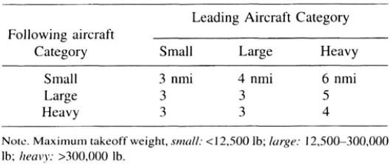
The approach controller's principal task is to sequence, merge, and space the aircraft for landing. When the leading aircraft crosses the approach end of the runway, the following aircraft must be spaced a prescribed minimum distance behind. The separation minima are established to protect the following aircraft from upset due to wake turbulence generated by the leading aircraft and depend upon the maximum takeoff weights of the aircraft involved (Table 14.1).
The task of establishing properly spaced landing sequences without encumbering aircraft operations with unnecessary vectors and speed adjustments is demanding in heavy traffic conditions. In vectoring an aircraft off its route of flight, a controller assumes responsibility for its navigation including clearance from obstacles and terrain. To ensure adequate clearances, minimum vectoring altitudes are established within terminal areas, and IFR aircraft are maintained above these altitudes as they approach the airport.
Aircraft noise is the principal factor limiting airport capacity. At some airports, specific noise abatement routes have been defined (e.g., along rivers) to channel the noise where relatively few people will be affected. These routes can be complex (require a number of turns within restricted geographical areas), and it may not be feasible to site navigation aids to support them. Hence, some of these routes are flown with visual reference to the ground and published as charted visual procedures.
TABLE 14.1 Wake turbulence separations for landing
The approach controller generally hands off traffic to the local controller when it has been established on the final approach course. The local controller hands off to the ground controller as the aircraft taxis off the active runway.
The flight crew's principal responsibilities during approach and landing are to navigate the cleared route of flight, respond to controller instructions, maintain visual separation from other aircraft, and manage the aircraft configuration (flaps and gear) and dynamics (speed, altitude, and rate of descent) for landing. Entry into the terminal area may be along the STAR requested in the filed flight plan, and the aircraft may then be cleared for an instrument, visual, or charted visual approach, with or without vectoring for the transition. Prior to entering the terminal airspace, the crew listens to ATIS communications for essential information on airport and navigation aid conditions.
14.4.5 Oceanic
The ATM processes described in the preceding sections are based on controllers having reliable, accurate radar surveillance information and nearly instantaneous voice communications with flight crews. With some exceptions, neither of these conditions prevailed in oceanic airspace in 1996. Flight crews generated position reports by determining their positions using inertial reference units having drift rates of 1 to 2 nmi/hr and communicated these reports to controllers when over mandatory reporting points spaced every 500 nmi along the route of flight. Air-to-ground communication for periodic position reporting and control instructions in 1996 was dependent upon relatively unreliable high-frequency (HF) voice links with contacts sometimes requiring many minutes to establish. The consequence of the relatively inaccurate navigation, cumbersome communication, and little real-time surveillance was large separation standards that poorly utilized the available airspace. By 1995, successful experiments had been accomplished using air-to-ground data communication via geostationary satellites for the transmission of aircraft derived position and velocity data (either from inertial navigation systems or GPS receivers) to achieve satellite-based automatic dependent surveillance (ADS) (Section 14.5.3). A few transoceanic airlines had implemented the required equipment (called FANS 1) to use this technique on a regular basis on commercial flights in 1996.
To organize traffic so that controllers can effectively ensure separation, track systems are established in heavily traveled oceanic areas (e.g., over the North Atlantic). A track system is a set of nearly parallel routes, each joining oceanic gateways (fixes) on the two sides of the ocean. Some of the track systems are flexible in that they are adjusted twice daily to provide fuel-efficient routing matched to prevailing wind and weather conditions (pressure pattern navigation). Overland en-route airways carrying traffic to and from the ocean connect with the oceanic routes at the gateways. The overland route segments are within radar coverage and are used for sequencing, merging, and spacing the traffic into oceanic airspace. Track systems, even with flexible tracks, are inefficient in terms of aircraft operations. The ultimate objective is to achieve RNAV routing, with each aircraft following the route, speed and altitude profiles best adapted to its operating requirements. It is expected that GNSS (Section 14.5.1 and Chapter 5), automatic dependent surveillance (Section 14.5.3) and satellite communications (Section 14.5.4) will facilitate widespread use of RNAV routing in oceanic airspace.
14.5 SUBSYSTEMS
The ATM system is a complex interconnection of communications, navigation, surveillance, aviation weather, and automation subsystems [13, 39]. They interact with corresponding aircraft subsystems, in some cases automatically via RF data links and in others manually based on pilot-controller voice communications and manual data entry. In the future, automatic data link communications will increasingly be used to reduce the work load and the potential for errors inherent in voice communications.
The voice and data communications network that interconnects U.S. traffic control centers, radars, etc. is operated by the FAA is second in size only to that operated by the U.S. Department of Defense. The network carries weather data, flight plans, facility control and maintenance information, traffic flow management and control instructions, surveillance data, and notices to airmen (NOTAMs) [13, 39]. A NOTAM provides current information for flight operators concerning the establishment, condition, or change in any component (facility, service, procedure, or hazard) in the system. The interfacility communications network interfaces with international ATM networks (e.g., to exchange international flight plans) using protocols established by ICAO. It interconnects with other U.S. government agencies to coordinate aircraft operations and exchange data (e.g., weather information).
14.5.1 Navigation
In 1996, only VOR/DME and VORTAC were accepted as sole means systems for en-route and terminal navigation under instrument flight rules. A sole means air navigation system is a system approved for specific phases of air navigation without the need for any other navigation system in the aircraft. A supplemental air navigation system can be used to enhance navigation performance, but the aircraft must also carry and use the sole means system approved for the particular phase of flight. In 1996, IRUs (Chapter 7) and Omega (Chapter 4) were accepted internationally as sole means navigation systems over oceans and GPS was accepted as a sole means navigation system in U.S. oceanic flight information regions (Section 14.6.6).
In 1996. guidance for precision approaches and landings was primarily provided by ILS and MLS (Chapter 13). NDBs, localizers. VOR/DME, GPS, VORTAC, Loran-C (Chapter 4), and IRUs (Chapter 7) are approved for nonprecision approaches to appropriate minimums. Precision and nonprecision radar approach procedures had been established. During radar approaches, flight path guidance instructions are transmitted to pilots by controllers monitoring the aircraft positions relative to prescribed approach paths. A precision approach procedure provides the pilot both route and height (glidepath) guidance to the decision height. A nonprecision approach procedure provides only route guidance; the pilot controls the altitude of the aircraft based on the altimeter reading and the charted procedure. Decision heights are lower for precision approaches because the height of the aircraft relative to terrain and obstructions can be controlled more accurately.
The development of navigation systems to meet civil and military requirements is a subject of intensive planning among users and providers of navigation services. In the United States, a principal product is the comprehensive Federal Radionavigation Plan (FRP) published biannually [591]. In 1996, two major development efforts were underway, one focused on establishing and implementing the concept of required navigation performance (RNP) and the second focused on the global navigation satellite system (GNSS). In contrast, the method most commonly used at that time to prescribe the minimum navigation performance required of aircraft operating in a given airspace was to require the installation of specific equipment. These requirements were often subject to international agreement and hence cumbersome to change. This situation constrained the effective application of new navigation technology and imposed heavy work loads on standards organizations, especially ICAO, trying to keep pace with technology improvements. Initially, the GNSS was represented by the U.S. Global Positioning System (GPS, Section 5.5). In the future, the Russian Global Orbiting Satellite System (GLONASS, Section 5.6) is expected to be part of the GNSS. The emergence of the GNSS has lead to the RNP approach.
RNP is a statement of the navigation accuracy required for operation within a defined airspace [22]. The navigation accuracy prescribed is the total system use accuracy (Section 2.7), including ground-station or space-station equipment errors, aircraft receiver and display errors, and flight technical errors. The RNP concept will be applied to all phases of flight, including approach and landing. Providers of air traffic services, in collaboration with airspace users, will determine the level of navigation performance required to ensure the safety and efficiency of flight operations in a given airspace and will specify the corresponding RNP. To simplify this process for airspace planners, manufacturers, and operators, ICAO is standardizing the RNP types. In 1996, four types were proposed, RNP 1, RNP 4. RNP 12.6, and RNP 20. The figure in each RNP type designation is the accuracy required on a 95% probability basis. For example, aircraft in RNP 4 airspace are required to be within 4 nmi of their intended positions in the horizontal plane 95% of the time. RNP 1 is expected to support operations along routes where the most accurate positioning of aircraft is required, including transitions to and from airports and operations along parallel offsets. Parallel offsets are routes offset laterally from the planned route center line by a specified distance. Operations along such offsets may be advantageous for passing slower traffic, for increasing airspace capacity and/or for facilitating uninterrupted climbs and descents where there is conflicting traffic on the planned route. RNP 4 corresponds to VOR navigation practices (Section 14.3.1), and RNP 12.6 corresponds to the nominal capabilities of inertial reference units on long oceanic flights. RNP 20 is the minimum capability considered acceptable to support en route traffic operations. It is the responsibility of the aircraft operator and the associated national airworthiness authority (the FAA in the United States) to ensure that an aircraft operating in a specified RNP airspace is equipped to achieve the required navigation performance. It is expected that the RNP concept will foster the effective application of new navigation technologies as they become available.
In 1996, the civil aviation community is moving rapidly to establish and exploit the two global navigation satellite systems, namely, GPS and GLONASS. After GPS achieved initial operational capability in late 1993, aircraft in the United States equipped with the approved avionics 115) were authorized to use GPS on a supplemental basis for some phases of flight. The principal issues in relying solely on GPS for route navigation are the availability of the system (i.e., the percentage of the time GPS will provide a sufficiently accurate navigation service) and the integrity of the system to provide timely warnings of satellite or system failures. In 1996, the development of the FAA's Wide Area Augmentation System (WAAS) (Section 5.7.3) was under way, with the aim of providing the required availability, integrity and accuracy for certain flight operations, including nonprecision and Category I precision approach (Section 13.8). In 1995, GPS augmented by local differential GPS (DGPS) corrections satisfied the requirements for so-called DGPS Special (private use) Category I approaches (Section 5.5.9). A number of issues pertain to the use of differential GPS for Category II and III approaches, including the practicality and cost effectiveness of augmentations to provide the necessary accuracy and integrity (Section 13.8); however, experimental test results obtained in 1995 were extremely promising.
Separation Standards Separation standards are determined by the density and complexity of traffic movements, the aircraft's navigation system performance and the communication, surveillance and automation capabilities that permit controllers to intervene in order to modify flight paths. Separation standards, in turn, determine the amount of airspace that must be protected for each route and aircraft. Efficient, flexible use of airspace is fostered by reduced separation standards and application of RNAV capabilities that permit operators to fly point to point as opposed to constraining their operations to fixed routes and airways. GNSS is expected to provide the accurate, ubiquitious RNAV capability required. The international airline community has estimated that a fully implemented GNSS will reduce their costs by $5 billion annually.
14.5.2 Radar Surveillance
The radar surveillance subsystem provides controllers information on the three-dimensional positions of aircraft. In ATM, two types of radar systems are used: Primary radar (or search radar) determines target range, azimuth, and, in some cases, elevation from the signal reflected back by the aircraft skin. The main beam of the ground station antenna pattern is broad in elevation (e.g., 40 deg) and narrow in azimuth (e.g., 2 deg). As the antenna rotates (scans) about its vertical axis, pulses of radio frequency (RF) energy are transmitted, and the signals scattered back by the surface of the aircraft are received. The target range is determined by the round-trip time between transmission and reception (the energy travels at the speed of light) and the azimuth is determined by the pointing angle of the antenna main beam (Figure 14.6). Target elevation can be determined by a second antenna pointed along the target azimuth which scans in elevation (i.e., scans around a horizontal axis). Such height-finding radars are not commonly used for civil aviation purposes but do find application in the military (e.g., radars used for controlling precision approaches).

Figure 14.6. Primary radar.
The advantage of primary radar is that accurate target position reports can be generated without any participation on the part of the target aircraft. The disadvantages are that the ground-station equipment is expensive, performance is limited by the target size and the range, and it degrades when the transmitted signal is reflected back by terrain or weather (clutter), obscuring returns from aircraft, and the aircraft cannot be uniquely identified (e.g., as “Central Airlines Flight 34”). Nonetheless, primary radar is a mature technology widely used for ATM [57].
In the secondary radar (or beacon radar) system, the signal transmitted from the ground-station antenna (commonly mounted on top of a primary radar antenna) initiates the transmission of a reply signal from the transponder (receiver/transmitter) in the aircraft. The system essentially provides two-way air-to-ground data communications and operates in several modes [23, 38, 45, 56]. As shown in Figure 14.7, Modes A and C use simple three-pulse, pulse-position modulated (PPM) interrogations with P1 and P3 having equal amplitudes. When the P1–P3 interval is 8 μsec (Mode A interrogation), the transponder replies with the aircraft identification (ACID) code; if the interval is 21 μsec (Mode C), the reply will contain the encoded altitude of the aircraft. At short ranges, the signal strength may be sufficient to interrogate transponders via the antenna side lobes. To avoid this situation, aircraft in the antenna side lobes are prevented from replying through a technique called transmit side lobe suppression. The P2 pulse of the interrogation (Figure 14.7) is transmitted on an omnidirectional antenna at a slightly higher power density than that produced by the antenna side lobes. Transponders are designed to reply only if the received P1 pulse is greater than the received P2 pulse. This condition is not satisfied in the side lobes of the antenna. It is essential to suppress transponders in the side lobe regions because their replies would be erroneously displayed at the azimuth corresponding to pointing direction of the mainbeam.
The replies are also PPM signals with 13 data pulses uniformly spaced between 2 “framing pulses” separated by 20.3 μsec. The special identification (SPI) pulse, when present, follows the last framing pulse in Mode A replies only. In Mode A replies, 12 of the 13 data pulses are used to communicate the ACID code as one of 4096 possible codes. This code is assigned to each IFR aircraft in the route clearance and is set into the transponder by the flight crew. (VFR aircraft transmit the code “1200” to identify the aircraft as not under ATM control.) The controller writes the assigned ACID code into the flight plan. Ground automation equipment correlates ACID codes with flight plans as Mode A replies are received from the surveillance site and determines the aircraft identification (e.g., Central Airlines Flight 34) corresponding to each. Through this process, the aircraft identification can be displayed in the data tag associated with the aircraft position on the controller's display (Figure 14.12 and Section 14.5.6). To contact the aircraft over VHF, the controller can read the identification directly from the display.
The SPI pulse is inserted into a Mode A reply as a result of the pilot depressing the IDENT button on the transponder control panel. Ground-based automation display equipment will blink the data block of an aircraft from which the SPI pulse is being received. Controllers will ask pilots to IDENT during hand-offs and at other times when it is necessary to quickly and unambiguously locate aircraft on their displays.

Figure 14.7. Secondary radar Mode A and Mode C (interrogation at 1030 MHz; response at 1090 MHz).
In Mode C replies, the 12 data pulses provide the pressure altitude of the aircraft in 100-ft increments from −1000 ft to 126,700 ft. All Mode C altitude reports are referenced to 29.92 in. of mercury.
Mode S has been added to reduce or eliminate some of the performance limitations of Modes A and C. For example, with Mode A, at some major airports two or more aircraft with the same ACID code may be operating in the area at the same time and the ground automation will not be able to identify these aircraft unambiguously. In addition, when two aircraft are in the antenna main beam simultaneously and close in range (e.g., one above the other), their replies will overlap and obscure one another. Mode S uses more sophisticated interrogation and reply modulation wave forms (Figure 14.8 and Section 14.5.4), permitting discrete addressing of aircraft. Data blocks have 56 bits in the short format and 112 bits in the long format. Error detection coding ensures undetected message error rates of less than 1 in 107. A unique 24-bit Mode S address is assigned to each aircraft so that aircraft can be unambiguously identified and addressed worldwide. There are more than 16 million available Mode S addresses with specific blocks assigned to every country by ICAO. A ground station with Mode S capability addresses each Mode S capable transponder by its unique address thereby establishing a private-line communications service. By managing interrogations properly in time, the ground station can ensure that replies do not overlap. The private-line capability of Mode S supports general-purpose data link communications capability for which a number of applications were under development in 1996 (Section 14.5.4). All secondary radar ground stations and aircraft transponders are capable of operating in Modes A and C. Where Mode S is added, Modes A and C are retained in the equipment to ensure that the equipment can operate compatibly with equipment having only Modes A and C.
Given a series of surveillance reports from a target aircraft, ground automation equipment estimates the target velocity over the ground by tracking the reports. In the most elementary form, the estimated velocity vector is in the direction joining the two most recent reports with a magnitude equal to the distance between the reports divided by the time interval between them. U.S. Federal Aviation Regulations require the installation of transponders with specified capabilities in various airspace regimes in order to support the ATM services provided and to ensure safety.
14.5.3 Automatic Dependent Surveillance
As shown in Figure 14.9, automatic dependent surveillance (ADS) is a function that automatically transmits, via a data link, position data derived from the on-board navigation system [2, 46]. The purpose of ADS is to provide real-time surveillance information to ATM authorities and aircraft operator dispatch facilities. Surveillance is dependent in this technique because its operation and quality depend upon the performance of the aircraft's navigation system. According to the ICAO definition [24, 30], as a minimum, the ADS data includes time of day, aircraft identification, and three-dimensional position information. Additional information reported may include aircraft speed and direction, the waypoints stored in the navigation system and meteorological data (static air temperature and velocity of winds aloft). The route data, including the next waypoint and the (next +1) waypoint with the corresponding planned altitudes, enable controllers to check conformance with their flight plans for the aircraft. The interval between ADS reports can be controlled by the controller responsible for the flight. Figure 14.9 depicts the use of a geostationary communication satellite as a relay data link medium, which is typical for overocean operations. Alternatively, over land areas, a VHF or L-band direct data link from the aircraft can be used. In 1996, the initial application of ADS was in oceanic airspace, with reporting intervals ranging between 30 sec and 5 min. Over land areas, the reporting intervals are expected to range from 10 sec (or more) in en-route airspace to 4 sec in terminal areas.

Figure 14.8. Mode S waveforms.
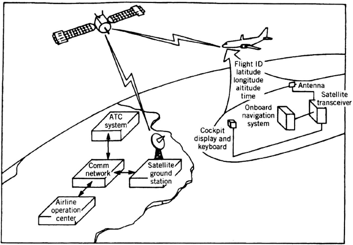
Figure 14.9. ADS concept.
14.5.4 Air-to-Ground Data Link Communications
The performance of the ATM system is critically dependent upon the quality of the information available within cockpits and within ATM and aircraft dispatch and flight planning facilities. Much of the information required at any of these sites is collected and processed elsewhere. Therefore, high capacity, reliable air-to-ground communications capabilities are required.
In 1996, air-to-ground information exchange was accomplished largely using VHF voice communications, but it was realized that digital data communications (data link) capability is needed to support a number of applications. The development of this data link capability was well under way in 1996 and in use for some applications; for example, for providing predeparture clearances to aircraft. In the future, aeronautical information such as weather data, ATIS, and NOTAMs will be provided on pilot displays and as printed copy in the cockpit to reduce transmission errors and work load. As more automated ATM processes are developed, data link will be required for exchanging flight plans and route clearances as well as to transmit ATC instructions to the cockpit, including altitude and VHF frequency assignments. In addition, data link will be used to provide automatically to flight crews traffic advisories derived from surveillance data resident in ground-based ATC centers, as well as to alert crews when they are about to enter special use airspace or airspace such as Class B (terminal control areas) where operations are closely regulated.
Efforts by ATM authorities to establish data link capability have been bolstered by complementary initiatives among the airlines focused on more efficient fleet scheduling and flight and maintenance operations. Engine performance is monitored automatically on board many aircraft with some parameters automatically transmitted to the ground for fault detection and trend analysis. Flight plans are sent to aircraft and stored automatically in the flight management system (FMS) computer (Section 14.5.7), with position reports, fuel status, estimated arrival times at waypoints, and wind and static air temperature data sent to the ground automatically on request. Data link is a principal tool for fostering improved safety and efficiency of flight operations.
Three data link media have been developed. VHF data link uses 25 kHz-wide channels in the frequency band 118–136 MHz [41]. Minimum shift keying (MSK) modulation is used to achieve data rates of 2400 bits/sec. In the future, offset quaternary phase shift keying (OQPSK) modulation techniques may be employed to increase the data rate to 21 kbits/sec. A principal advantage of VHF data link is the low cost of the ground stations and aircraft equipment. While a large number of data channels could be accommodated within the 18 MHz assigned for air-to-ground VHF aeronautical communications, the number available in practice is limited by heavy competition from voice traffic. In 1996, the airlines employed VHF data link for company purposes worldwide, and the FAA is using it to transmit predeparture clearances to appropriately equipped aircraft in order to reduce the work load of tower controllers and expedite departure operations.
By virtue of its discrete address feature, Mode S provides a wideband, general-purpose data link capability [47]. Ground-station interrogations are transmitted in a single 8 MHz-wide channel at 1030 MHz with transponder replies provided in a 2.6 MHz-wide channel at 1090 MHz. Differential phase shift keying (DPSK) modulation is used within interrogations to provide a 4-Mbit/sec data rate. Replies use pulse position modulation (PPM) with a 1-Mbit/sec data rate (Figure 14.8). A principal advantage of the Mode S data link is that it is integral with the surveillance system, which permits ground stations and transponders to efficiently support both functions. In addition, a number of data link applications (e.g., automatic traffic advisories and airspace alerts) are closely related to surveillance functions, and their implementation is therefore simplified when Mode S is used as the data link medium.
Digital data and digitized voice communications capability via satellite data link have been implemented to service oceanic regions and continental land areas where the establishment of ground stations is impractical [3, 25, 48, 49]. Satellite-to-aircraft communications operate in the 1.5 to 1.6 GHz frequency band (L-band) with ground-to-satellite links operating in Ku- or C-bands. In 1996, four channel types were used, three operating in a packet-switching mode for data and one in a circuit-switching mode for voice. For data rates between 600 and 2400 bits/sec, binary phase shift keying (BPSK) is used on the satellite-to-aircraft link with quaternary phase shift keying (QPSK) used for data rates from 4800 to 21,000 bits/sec. Voice transmissions are encoded at 9600 bits/sec. The principal advantage of satellite-based data link is that ground stations within line of sight of the aircraft are not required. Worldwide communications with aircraft can be assured between 80-deg North and 80-deg South latitudes using only three or four geostationary satellites and a like number of ground stations servicing those satellites. In practice, a larger number of ground stations (about 10 in 1996) is used to ensure reliability and competition in the provision of services. The principal disadvantage is that service is relatively expensive due to the high costs of satellites in orbit and the associated ground stations and aircraft equipment. In 1996, the principal application of satellite-based data link was ADS and associated oceanic ATM improvements.
A communications protocol is a set of rules governing the exchange of data between two entities (e.g., a computer and a display system or two computers). Typically, protocols specify data formats and coding; processes for coordination, acknowledgment, and error handling; and how data are to be sequenced and timed [55]. For air-to-ground data links, there could be a protocol developed for every cockpit entity to communicate with every ground-based entity over each of the three available media. This approach is impractical, because each entity would be required to implement a large number of protocols, and every time an entity was modified or added, every connecting entity would need to be modified to add a new protocol. One alternative is the approach selected for packet data communications within the Aeronautical Telecommunications Network (ATN). (See Figure 14.10). Avionics entities and ground-based entities are grouped into subnetworks connected to the three data link subnetworks through routers, subnetwork nodes that serve as gateways. A network (or subnetwork) is a collection of nodes to which communications entities connect, the links joining those nodes, and the protocol governing exchange of data among the nodes (Figure 14.11). Within the ATN, the avionics subnetwork connects the avionics entities and may operate according to a protocol peculiar to the aircraft type or the avionics equipment (Figure 14.10). The data link subnetworks connect any number of aircraft through avionics routers in each to any number of ground subnetworks through ground routers. The ground subnetworks operate in accordance with whatever protocols are best suited to their requirements.

Figure 14.10. Aeronautical telecommunications network.
The ATN has adopted the International Organization for Standardization (ISO) open-system interconnection (OSI) 7-layer protocol architecture [50, 55].
14.5.5 Aviation Weather
Flight crews require reliable weather information both pre-flight and in flight for planning and decision making, and air traffic controllers need timely, accurate weather data in order to aid flight crews in avoiding hazardous weather areas. Weather products unique to aviation are needed to support these requirements including forecasts of icing conditions, turbulence, ceilings and visibilities, winds aloft, and wind shear.
The production of weather products requires observations of existing weather conditions, modeling to forecast future conditions, and timely distribution of products tailored to user needs. In the United States, this is a large-scale undertaking that involves the FAA, the National Weather Service (NWS), and airspace users [29, 31]. Observations are made by ground-based sensors, aircraft sensors, flight crews in flight and space-based systems. These observations are assimilated into FAA, NWS, and airline data bases from which products are derived by forecasting models and filters that screen out the relevant information for users. The long-range objective is to ensure that all aviation weather product users are provided forecasts that are both reliable and consistent. Consistency is essential for ensuring that all concerned planners and operators are working with the same assessment of the weather situation so that their decisions and plans will be consistent as well.
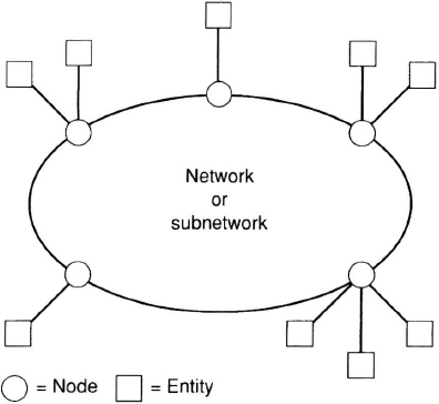
Figure 14.11. Communications network.
14.5.6 Automation and Display Subsystem
The automation and display subsystem interfaces with the air traffic controller and with surveillance, weather, and communication subsystems [57]. The surveillance subsystem provides primary and secondary radar target reports in both analog video and digital message formats. The analog formats are used only with the older radars that are gradually being replaced. The surveillance subsystem also provides radar reflectivity data from weather cells. The weather subsystem provides weather information derived from weather radars, such as the next generation weather radar (NEXRAD) and the terminal Doppler weather radar (TDWR), and from weather sensors, such as the low-level wind shear alert system (LLWAS). The communication subsystem provides the voice and data communications circuits necessary for controllers to communicate with aircraft and with other controllers both within the local facility and at other ATM facilities. Although the controller workstation configuration is somewhat different in the en-route and terminal environments, the basic components are similar. It consists of a situation display, a keyboard, and a trackball as well as means for displaying flight plan data and for controlling air-to-ground and ground-to-ground communications.
The situation display is oriented with North at the top and depicts the air traffic situation in relation to navigation aids, fixes, obstructions, airports, and runways (Figure 14.12). It also presents automation alerts to the controller. The information provided includes the aircraft position symbols with the associated flight data blocks, a list of safety alerts (i.e., minimum safe altitude warnings and conflict alerts), and a list of arriving and departing aircraft.
In Figure 14.12, there is an aircraft on the display in the 9 o'clock position. The data block shows that the aircraft identification (radio call sign) is N24F, its altitude is 5000 ft, and its ground speed is 210 Kn. The position of the aircraft is at the symbol “W” at the end of the leader line from the data block. The “W” designates the controller responsible for the aircraft, in this case, the west controller. The blinking “CA” displayed below the data block is a conflict alert to the controller based on the automation system's assessment that N24F and CAL 73 may lose standard ATC separation if the controller does not intervene. Aircraft DEL 476 in the 5 o'clock position is below the minimum safe altitude at its location and the automation therefore has generated a low altitude alert (a blinking “LA”). The aircraft to the southwest has only a limited data block because the automation has no flight plan for the aircraft. The data block shows that the aircraft's identification code (ACID) is 4724 and its altitude is 6000 ft. Its radio call sign is unknown. The data block for TUL41 at 4 o'clock is blinking because the aircraft is in the process of being handed off from the east controller to the west controller.
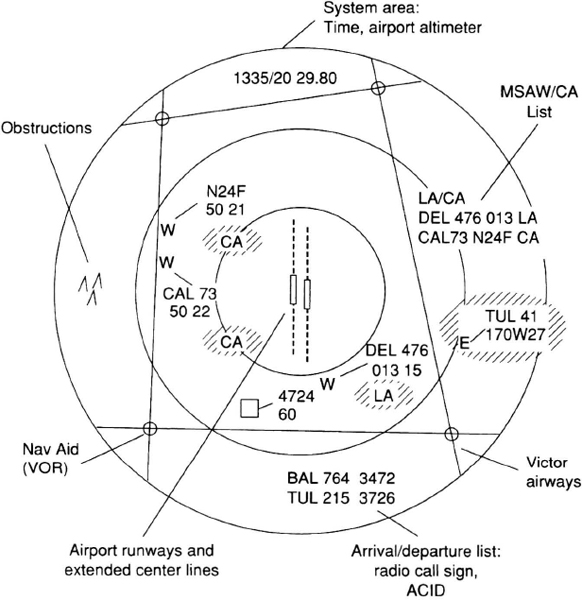
Figure 14.12. Radar situation display data presentation.
14.5.7 Airborne ATM Subsystems
Aircraft are equipped with a number of subsystems that interoperate with the ground-based system, including voice and data link transceivers, navigation receivers and computers, secondary surveillance radar transponders, and, in some cases, instrumentation for sensing wind velocity, air temperature, and turbulence. Increasingly, flight management systems (FMSs) are employed routinely to guide aircraft along their flight trajectories, and their full integration with the ATM system has been a subject of intense development [19, 32, 54]. The FMS has three specific capabilities relevant to ATM [54]. It can guide the aircraft accurately along a predetermined path defined by a sequence of two-dimensional (latitude and longitude) or three-dimensional (adding altitude) waypoints. The FMS also can minimize the cost of the flight by selecting optimum speeds and/or altitudes along the predetermined path. The optimization is based on a pilot-selected cost index that weights fuel cost relative to flight time cost. When the cost of flight time is weighted heavily, the FMS will complete the trip more quickly, burning more fuel in the process. Finally, the FMS has a required time of arrival (or 4D navigation) capability that assures the aircraft will arrive at selected waypoints within small time windows (e.g., within ten seconds of the prescribed times).
Extensive data bases are resident in the FMS, as well as the current flight plan and the wind velocities and air temperatures expected along the route of flight. The FMS provides pitch, steering, and autothrottle commands to the aircraft guidance systems, as well as essential flight data, including estimated times of arrival at waypoints, fuel remaining and fuel flow, current position and speed, and current winds. The FMS integrates the various avionic subsystems, including the navigations sensors (Figure 14.13). It will automatically tune VOR/DME receivers according to the position of the aircraft and the navigation aid frequencies stored in the data base.
Data link interfaces with the FMS have been developed to allow flight data, flight plans, ADS position reports, and wind data to be transmitted to the ground and new flight plans and information requests to be sent to the aircraft. The FMS is the airborne automation system controlling the flight path of the aircraft. Linking its operation to ground-based ATM and airline dispatch operations has obvious advantages. An early application was FMS-guided terminal procedures that allowed aircraft to fly complex procedures (e.g., charted visual approaches) in IMC, thereby providing access to runways otherwise not available. An early application of 4D navigation capability is expected to be assigning aircraft specific times for crossing oceanic gateways into track systems so that the tracks with the most favorable winds can be fully utilized. Future applications will involve dynamic reclearance of aircraft on long oceanic flights to adjust flight paths to changing wind and weather patterns. The scenario may involve the airline dispatch automation system computing a new plan and data linking it to the FMS where it would be checked by the flight crew. The crew would then send the plan to ATM via the FMS. When ATM is satisfied that the plan meets separation requirements, it would be transmitted back to the FMS where the crew would select it to actively guide the aircraft. Similar applications are expected in terminal airspace for metering traffic to airports and negotiating fuel-optimal descent and approach trajectories [19].

Figure 14.13. Flight management system.
14.6 FACILITIES AND OPERATIONS
The air traffic management services provided in the United States include traffic flow management, air traffic control, and flight services. The traffic flow management services are provided by the air traffic control system command center (ATCSCC) in conjunction with regional (en-route) and terminal facilities. ATM services are provided by air route traffic control centers (ARTCCs) at the regional level, and by approach control facilities and airport-traffic control towers (ATCTs) at the terminal and local levels. Flight services are provided principally by flight service stations (FSSs). Some flight services are also provided by ARTCCs and terminal facilities.
14.6.1 National Traffic Management
In the (ATCSCC), traffic managers monitor the national flow of air traffic to identify situations where demand may exceed capacity. This capacity/demand imbalance is often caused by a surge in demand at peak traffic hours or by a reduction in the capacity of a resource (e.g., an airport) due to weather or loss of essential ATM equipment. The traffic managers are provided graphical displays of traffic as well as automation tools to predict capacity/demand imbalances and to aid in formulating and implementing strategies to cope with excess demand. An automation tool periodically checks the estimate of demand on each resource (airport, sector, and fix), monitored against the capacity of the resource to determine if any will be saturated in the near future. As soon as a capacity/demand imbalance is predicted, the traffic manager develops a strategy to prevent its occurrence or to mitigate its effects. The strategy is often developed in coordination with the affected airlines and with the traffic management units (Section 14.6.2) and terminal facilities responsible for the aircraft involved. The strategies commonly considered include reroutes, delaying aircraft en route using speed adjustments or holding procedures, and holding aircraft on the ground at the origin airports.
14.6.2 En-route Facilities
The ARTCC provides ATM services to aircraft operating under instrument flight rules (IFR) in the en-route airspace. In 1996, there were 20 ARTCCs in the continental United States. They received surveillance data from long-range air route surveillance radars (ARSRs), and communicated with aircraft through ground-based transmitter/receivers located at remote communication air-to-ground (RCAG) sites. The ATM services provided at the ARTCC include aircraft separation and traffic flow management. The flow management services are provided by traffic managers in the traffic management unit (TMU) who work closely with sector controllers and traffic managers at the ATCSCC to formulate and implement traffic flow instructions. These instructions are designed to minimize delays while ensuring that excessive levels of traffic congestion are prevented.
The principal automation functions performed at the ARTCC include flight plan processing, metering, weather data processing, target tracking, tactical separation assurance based on target tracks, and strategic separation assurance based upon aircraft flight plans.
Flight Plan Processing The flight plan processing function accepts flight plans filed by pilots through flight service stations, airline operations offices, military base operations, or sector controllers, as well as flight plans filed in bulk form by airlines. The flight plans are processed to produce flight progress data for posting to all controllers (en route and terminal) within the ARTCC airspace who will control the flight. The flight plan data are then passed to the next ARTCC along the route of flight. In 1996, flight progress data were presented to controllers on paper medium (i.e., as flight strips).
Metering The metering function assists traffic managers and sector controllers in avoiding unacceptable levels of traffic congestion. Traffic managers in the TMU run the metering program during periods of peak traffic demand or may issue metering instructions based on their judgment and experience. The metering instructions provided to controllers may include meter fix crossing times for specific aircraft arriving at a terminal area or in-trail spacing restrictions (e.g., all aircraft being handed off to a congested adjacent sector must be separated longitudinally by 20 nmi).
Weather Processing The weather-processing function accepts real-time weather radar reflectivity data from FAA and military surveillance and weather radars as well as processed weather data from a number of sources. These data are displayed on the sector controllers' plan-view situation displays so that the controllers can route aircraft around severe weather and provide weather advisories to pilots as required.
Track Processing and Tactical Automation Functions The en-route automation system tracks all aircraft from which either primary or secondary target reports are received. The tracking process establishes a velocity vector for each tracked aircraft. The aircraft position and velocity data are used by the tactical separation assurance functions, namely, conflict alert. Mode C intruder, and minimum safe altitude warning (MSAW). The conflict alert function projects aircraft positions approximately two minutes into the future and searches for violations of separation minima between IFR aircraft (i.e., between aircraft for which the automation system has flight plans). The Mode C intruder function provides a similar service for IFR aircraft in relation to VFR aircraft that are providing automatic pressure altitude reports in the Mode C replies from their transponders. MSAW provides the controller a warning when an aircraft is projected to drop below the minimum safe altitude for the occupied airspace. Aural and visual alerts are provided to the responsible controller when separation problems are predicted.
Strategic Separation Assurance Functions Automated problem detection (APD) and automated problem resolution (APR) are automated en-route ATC (AERA) functions planned for implementation in the late 1990s. They generate a four-dimensional (x, y, z, and t) trajectory for each aircraft derived from its current position, flight plan, and aerodynamic performance characteristics. As long as the aircraft operates within a threshold distance of this trajectory, the trajectory reliably represents the future path of the aircraft and therefore can be used as the basis for detecting conflicts. Based on 15- to 20-min projections of aircraft along these trajectories, APD detects conflicts with other aircraft, with restricted airspace and with flow instructions. APR will generate recommended control instructions for resolving each conflict, taking into account all aircraft operating in the vicinity. The responsible controller may elect to use these instructions or to resolve the conflict in another way.
14.6.3 Terminal Facilities
Approach control facilities provide services to aircraft within the terminal airspace delegated to the terminal facility by the parent ARTCC. The terminal airspace is sectorized into arrival and departure sectors to facilitate the flow of aircraft to and from airports.
In 1996, there were approximately 240 facilities in the United States providing approach control services. These include combined center/radar approach controls (CERAPs), terminal radar approach controls (TRACONs), terminal radar approach controls collocated with tower cabs (TRACABs), and military radar approach controls (RAPCONs). Of these terminal facilities, the FAA operated 133 small-to-medium TRACONs, 63 medium-to-large TRACONs, and 1 very large TRACON (the New York TRACON). During the mid-to-late 1990s, several large consolidated terminal facilities called Metroplex Control Facilities (MCFs) will be created by combining several TRACONs into a single facility. Terminal area controllers communicate with aircraft through transmitter/receiver sites known as remote transmitter/receivers (RTRs) and are provided short-range surveillance data by airport surveillance radars (ASRs). The principal automation functions performed at the terminal facilities include weather processing, target tracking, and tactical separation assurance based on target tracks (Section 14.5.6).
14.6.4 Airport Facilities
Airport ATM facilities are designated airport traffic control towers (ATCTs) or towers for short. In 1996, there were approximately 692 ATCTs in the United States, 419 operated by the FAA, 208 operated by the military and 65 operated by nonfederal entities.
Towers normally have four principal positions of operation (see also Section 14.4). These are the flight data, clearance delivery, ground control, and local control positions. The flight data position is responsible for the maintenance of flight data (flight strips) and for updating miscellaneous tower data, including the automatic terminal information service (ATIS). The clearance delivery position is responsible for issuing predeparture clearances to IFR aircraft. The clearance delivery and flight data positions are commonly combined and operated as a single position.
The ground controller is responsible for the safe movement of vehicles and aircraft within the airport movement area, with the exception of those operating on active runways. The local controller is responsible for movements on active runways. In 1996, local control and ground control operations were conducted principally through controller visual contact with the aircraft and ground vehicles being controlled. High-resolution primary radar is used at some major airports for detecting aircraft and ground vehicles on the airport surface and displaying this information to tower controllers. Development and testing efforts were under way in 1996 to improve surveillance and control of the surface using automatic dependent surveillance techniques (Section 14.5.3), based on the use of differential GPS (Section 5.5.9) and digital data links.
The level of automation support provided in ATCTs is dependent upon the activity level of the tower and the complexity of the air traffic operation. The smallest towers are provided with the capability to enter flight data, print flight strips and display environmental data. The largest towers have plan-view radar situation displays to support approach control operations and ground surveillance radars. During the late 1990s, the more complex towers will be provided with automation tools to assist in metering departures and to reduce the risk of aircraft collisions on the ground.
14.6.5 Flight Service Facilities
In 1996, flight services were provided in the United States by 131 flight service stations (FSSs). These facilities receive notices to airmen (NOTAMs) from the U.S. NOTAM system and weather products from the National Weather Service (NWS), including weather observations at airports, winds aloft, terminal and area forecasts, and weather warnings that describe significant meteorological events of importance to airmen. Section 14.4 describes the principal functions of flight service stations.
14.6.6 Oceanic Facilities
The oceanic airspace is divided into flight information regions (FIRs) under the auspices of the International Civil Aviation Organization (ICAO). The United States has responsibility for providing ATM services in several FIRs in the Atlantic and Pacific oceanic regions as well as one FIR over the Gulf of Mexico. The associated oceanic control centers are colocated with en-route facilities in New York, Oakland, Houston, Anchorage, and Honolulu.
14.7 SYSTEM CAPACITY
The demand on the ATM system continues to rise. For example, the number of aircraft handled by U.S. air route traffic control centers (ARTCCs) is forecasted to rise from 36.6 million operations in 1989 to 47.8 million operations by the year 2000. This growth in air traffic will put increased pressure on all system resources, especially the major airports.
The FAA's Aviation System Capacity Plan [16] defines the aviation capacity problem in terms of flight delays determined by comparing actual with optimal arrival times. In 1990, 23 U.S. major airports experienced more than 20,000 aircraft hours of flight delay. That number is expected to grow to 40 major airports by the year 2000 if capacity improvements are not implemented.
During the course of a flight, a number of system resources are utilized, including the departure airport taxiways and runways; terminal fixes and sectors; en-route fixes, routes, and sectors; and the arrival airport. Although any of these resources can become saturated and contribute to flight delay, historically, the departure and arrival airports are the principal contributors. Table 14.2 shows the sources of flight delays greater than 15 minutes as reported in the 1991–92 Aviation System Capacity Plan.
The following sections discuss techniques for reducing flight delays by reducing peak demand and increasing system capacity.
14.7.1 Reducing Peak Demand
There are a number of techniques to reduce peak demand, thereby reducing the severity of demand/capacity imbalances. ATM authorities can delay departures and slow down en-route traffic in order to reduce airport arrival demand during the peak hour. Another demand management technique is to encourage smaller aircraft to use reliever airports. In the United States, of the 40 airports forecasted to experience significant delay problems, approximately one-third have 25% or more general aviation operations. For those airports, shifting a portion of the general aviation operations to a reliever airport would reduce delays. A related technique is to shift demand to underutilized airports that are equipped to handle air carrier aircraft and are within 50 mi of saturated airports. Finally, underutilized airports can be used as connecting hub airports instead of congesting major metropolitan airports with passengers who are only transferring to other flights.
TABLE 14.2 Sources of flight delays greater than 15 minutes
14.7.2 Increasing System Capacity
The largest capacity gainers at airports are new runways. In 1996, 62 new runways or major runway extensions were planned or proposed at the top 100 U.S. airports. The next most productive capacity enhancement is improved terminal airspace procedures. In 1989, 57% of all flight delays were attributed to adverse weather conditions. These delays are a consequence of the fact that instrument approach procedures are more restrictive than the visual procedures in effect during better weather conditions. Much delay could be eliminated if the approach procedures used during IMC were more flexible.
Dependent Parallel IFR Approaches In 1996, simultaneous parallel approaches could be made in IMC to parallel runways spaced as closely as 2500 ft provided a 2 nmi diagonal separation is maintained between aircraft (Figure 14.14a). Parallel runways with dependent approach streams can accommodate 45% to 65% more arrivals per hour than a single runway (i.e., 44 to 50 arrivals per hour as opposed to 30 arrivals per hour for a single runway).
The diagonal separation requirement makes one arrival stream dependent on the other because it prevents a faster aircraft on one approach from passing a slower aircraft on the adjacent approach. This dependency limits the capacity benefit of the parallel runways as compared with two independent arrival streams. In the late 1990s, technology advances and procedural improvements may permit the reduction of the diagonal separation requirement to 1.5 nmi, which would increase the capacity of the dependent parallels by approximately four aircraft per hour.
Independent Parallel IFR Approaches During simultaneous independent approaches to parallel runways, each approach course is monitored by a dedicated monitor controller using a plan-view radar situation display. An aircraft on an ILS approach is established on the final approach course prior to the point where it intercepts the glide slope. Aircraft on parallel approaches (e.g., to 25L and 25R in Figure 14.14b) are separated vertically by 1000 ft prior to the point where the higher approach path intercepts the glide slope. From this point forward until the aircraft land, the monitor controllers ensure that the aircraft maintain lateral separation. In particular, if an aircraft on one approach course enters the no transgression zone shown in Figure 14.14b, the monitor controller responsible for the parallel approach course will vector away any aircraft that is threatened by the “blundering” aircraft.

Figure 14.14. Parallel approaches.
For parallel runways with center lines separated by 4300 ft or more, the standard airport surveillance radar, which has a 4.8-sec antenna scan period and uses a conventional controller display, has been used for monitoring simultaneous independent approaches. In 1995, a quick-scan radar called the precision runway monitor (PRM) was developed. Its 0.5-second scan period and its high resolution controller display system permit independent parallel approaches where runway center lines are separated by 3400 ft or more.
Independent approaches provide an increase in arrival capacity of approximately 30% as compared to dependent parallel approach procedures. A decrease in the runway center line spacing requirement through the use of new technology and procedures provides capacity gains for airports with limited real estate resources.
Dependent Converging IFR Approaches Independent converging approaches are generally permitted only when the ceiling is greater than 700 ft and the visibility is 2 smi or more. The principal aircraft separation problem arises when both aircraft execute missed approaches. If the ceiling is above 700 ft the pilots and tower controllers can ensure separation visually. At lower ceilings, either the approaches must be confined to a single runway or dependent approach streams must be established. In dependent converging approach streams, the aircraft are spaced longitudinally such that, if any two aircraft execute missed approaches and fly over the point where the runway center lines intersect, the aircraft will be separated longitudinally.
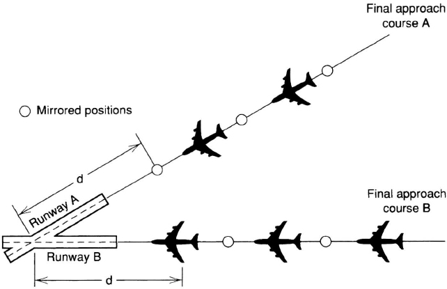
Figure 14.15. Converging dependent approaches.
To aid controllers in establishing dependent converging approach streams, the converging runway display aid (CRDA) was installed at a number of airports in 1995 (Figure 14.15). CRDA displays a mirror image of each approaching aircraft. As shown in Figure 14.15, the mirror image is drawn on the adjacent approach course at a distance from the runway intersection equal to that of the approaching aircraft. Controllers then space aircraft from the mirror images of aircraft on the converging course as well as from real aircraft on the same approach course. It is estimated that capacity increases of approximately ten arrivals per hour over single-runway arrival capacities are achievable with this procedure.
14.8 AIRBORNE COLLISION AVOIDANCE SYSTEMS
Airborne collision avoidance systems are installed in aircraft to provide ground-independent protection from midair collisions as a backup to the conventional ATC system. Within the United States, a two-member family of equipment called the traffic alert and collision avoidance system (TCAS) has been developed [17, 20, 26, 33, 51, 52, 61]. TCAS interrogates the secondary surveillance radar transponders installed in proximate aircraft and processes the replies to alert flight crews to potential conflicts. The protection provided is independent of ground-based equipment. Hence, a TCAS-equipped aircraft receives backup separation assurance service wherever it flies.
Figure 14.16 illustrates the conflict geometry when the aircraft velocities V1 and V2 are constant. VR is the relative velocity, R is the distance between aircraft 2 and aircraft 1, and m is the miss distance, that is, the distance between the aircraft at the closest point of approach (CPA). Vθ is the tangential velocity of aircraft 2 relative to aircraft 1. The time that it will take aircraft 2 to reach CPA is T. From Figure 14.16,

and
Combining Equations 14.2 and 14.3, and then using Equation 14.1, one obtains
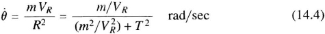
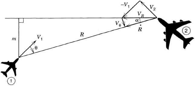
Figure 14.16. Conflict geometry.
where, from Figure 14.16,
Equation 14.4 illustrates the fact that the bearing rate ![]() is zero if and only if the aircraft are on a true collision course, m = 0.
is zero if and only if the aircraft are on a true collision course, m = 0.
The most widely implemented version of the TCAS family, TCAS II, interrogates the transponders on nearby aircraft, tracks the replies in range and altitude, and generates crew alerts if both range and relative altitude are predicted to be small at some time within the next 40sec or so. Two types of alerts are displayed: traffic advisories (TAs) and resolution advisories (RAs). A TA is displayed approximately 40sec prior to CPA and shows the range, bearing, and relative altitude of the intruder on a cockpit plan view display. If the intruder continues to close, an RA will be displayed approximately 25sec prior to CPA. The RA shows a vertical escape maneuver (e.g., “climb”) for avoiding a collision. Two TCAS II aircraft in conflict must exchange escape maneuver intentions to ensure that they are complementary (i.e., one aircraft climbs, the other descends). TCAS II uses Mode S air-to-air data link communications to perform the coordination function.
While TCAS II uses intruder bearing θ in displaying TAs, the angle-of-arrival-sensing antenna is not sufficiently accurate to provide bearing rate data for miss-distance, m, estimation. The time to CPA is estimated as tau. τ, where
This estimate is accurate in the critical cases where m is small. A principal disadvantage of TCAS II is that a certain number of unnecessary alerts are generated because miss distance cannot be estimated. In 1995, all air carrier aircraft with more than 30 passenger seats operating in U.S. airspace were required to be equipped with TCAS II.
TCAS I does not display RAs. The equipment tracks proximate aircraft in range and altitude and displays TAs for intruders that satisfy tau-based collision threat criteria. The TAs aid flight crews in visually acquiring threat aircraft so that visual separation can be maintained. By the end of 1995, TCAS I was required to be installed in all air carrier aircraft with 10 to 30 passenger seats operating in U.S. airspace.
14.9 FUTURE TRENDS
Since the air traffic management system consists of a large number of sub-systems, including communication, navigation, surveillance, automation, and weather service, there are a wide variety of future trends toward system improvements. They are discussed below.
One of the most profound trends will be the wide-spread use of air-to-ground digital data communication (versus voice) for interfacing automated, ground-based information sources with aircraft systems and flight crews. Use of data communication will result in more reliable and timely exchange of large quantities of data. In some airspace, voice communication will be used principally for emergency and nonroutine functions.
A second major, nearly revolutionary, trend will be the widespread use of satellite-navigation systems, initially, GPS (Section 5.5), to provide highly accurate, worldwide navigation information (position, velocity, and time) to meet RNP requirements for all phases of flight. In 1996, GPS was authorized by the U.S. FAA for use as a sole means system of oceanic navigation and for Special nonprecision and (private use) Category I SCAT precision approaches. In the future, in conjunction with the U.S. Wide Area Augmentation System (WAAS, Section 5.7.3), it will be authorized for use as a sole means system for terminal and en-route navigation, as well as public-use Category I precision approach operations. With a local area augmentation system (LAAS) (Sections 5.5.9, 13.8, and 13.9), Category II and III precision approach and landing capability is likely to be provided in the more distant future. Extensive research and flight experimentation, with very promising results, were in progress in 1996. In some highly congested areas, such as in Europe, MLS is likely to be used for some time in the future for providing precision approach and landing capability, particularly for Category II and III operations.
The use of GPS will be combined with GLONASS (Section 5.6) and possibly other satellite-navigation systems, to constitute a Global Navigation Satellite System (GNSS), thereby achieving a worldwide navigation capability based on at least 48 satellites. Geostationary satellites will also include a GNSS-like ranging function. This will lead to very high availability, integrity, and continuity of service characteristics and hence greater safety.
Aircraft equipped with a GNSS (initially GPS) receiver and a simple navigation computer will have RNAV capability, permitting direct routes anywhere on the globe. In the more distant future, rigid airways, based on networks of ground-based navigation aids (e.g., VOR/DME) will become obsolete. The flexibility of flight operations will be greatly enhanced, and ATM service providers will discontinue operation of some ground-based navigation aids.
Another major future trend will be the combined exploitation of rapid, automatic, air-to-ground digital communication and high-accuracy (e.g., GNSS) positioning capability to provide automatic dependent surveillance (ADS, Section 14.5.3) virtually everywhere, from oceanic airspace to the airport surface. The initial implementation of ADS will be in oceanic airspace and over remote land areas, and this will result in more cost-efficient separation standards, replacing the procedural separation methods still in use in 1996. The use of ground-based primary and secondary radars is likely to continue for terminal area surveillance for some time, but in the en-route environment it will ultimately be replaced by ADS because of its greater accuracy and cost effectiveness. Based on the successful experimentation and testing in the mid-1990s, ADS techniques (using local differential GPS and data link) are likely to be used for airport surface surveillance and control at major airports.
Ground-based automation to support national and local traffic flow management, as well as the more tactical ATC process, will be implemented on a large scale as the principal means for accommodating user-preferred flight trajectories and ensuring that system capacity resources are fully utilized to accommodate demand. ATM automation linked to FMS and flight dispatch automation by data link will ensure comprehensive planning of each flight trajectory, taking the needs of all other users into account. Four-dimensional (including time) clearances will be used where necessary to ensure aircraft separations and on-time arrivals at merge points. The FMS will guide the aircraft on fuel-optimal trajectories, meeting users' schedule requirements from wheels-up to touchdown. The traffic display capability of TCAS will be enhanced with additional information, such as the locations and orientations of runways and the identifications of proximate aircraft, to provide a comprehensive display of the ATM situation for the flight crew. The crew will then be able to participate more fully in planning and decision making, including resolution of local traffic conflicts in collaboration with the other aircraft involved.
An important future trend for air-to-air collision avoidance will be the widespread mutual exchange between aircraft of their accurately known present positions, as obtained from their on-board navigation equipment, such as a GPS receiver, to provide situation and threat information on all other aircraft in the vicinity. This technique is another means, other than basic TCAS, of achieving a ground-independent collision avoidance function for all participating aircraft. In this approach, only one-way broadcasts are used, which results in much larger communication capacities than with two-way transmissions. Also, heading and other pertinent data can be exchanged to reduce the number of unnecessary resolution advisories. This approach will improve the situational awareness performance of the collision avoidance system.
There is a strong trend toward development, evolution, and implementation of the concept of free flight [53]. Free flight is a flight operations capability, under instrument flight rules (IFR), in which the operators have the freedom to select their flight path and speed in real time, after interaircraft communications ensure safe separation. Air traffic restrictions are only imposed to remove a threat to safety, to preclude exceeding airport capacity and to prevent unauthorized flight through Special Use Airspace (SUA) [53]. The concept is intended to greatly increase a user's operational flexibility and “self-optimization,” while achieving guaranteed safety. The major technologies that will make it possible to accomplish these objectives are (1) efficient digital data links; (2) the global navigation satellite systems (e.g., GPS); (3) the concept of automatic dependent surveillance (Section 14.5.3) of continuously broadcasting (by all aircraft) the position, velocity, and short-term intent, used in conjunction with airborne collision avoidance computation equipment; (4) improved displays in the aircraft and at ATC centers to provide good situational awareness; and (5) revised air traffic procedures that capitalize on these newly available capabilities. Incremental evolution and implementation of free flight is likely to progress in the near term and continue for the foreseeable future.
The major overall theme for the future of ATM will be information fusion, providing to each user and provider of services an accurate, comprehensive awareness of the ATM situation, wherein automation systems perform the routine command, control, and guidance functions. Benefits will include increased safety and efficiency of flight operations worldwide, full utilization of system capacity resources, and reduced costs of ATM services. These new capabilities and the associated benefits will emerge first in oceanic airspace where existing ATM services have been rudimentary, the aircraft fleet is generally well equipped, and the operators are highly motivated to achieve fuel savings.
PROBLEMS
14.1. From the material in Section 14.8, show that miss distance can be expressed in terms of intruder range, range rate, and bearing rate as

14.2. It is proposed to use a TCAS antenna capable of measuring the angle of arrival (θ) of the intruder's transponder reply and to track these measurements in time to derive an estimate of bearing rate ![]() . The miss distance would then be estimated from the equation derived in Problem 14.1. Show that bearing rate estimation errors would need to be less than a few tenths of a degree per second. In particular, show that
. The miss distance would then be estimated from the equation derived in Problem 14.1. Show that bearing rate estimation errors would need to be less than a few tenths of a degree per second. In particular, show that ![]() deg/sec for m = 1.0 nmi, VR = 300 kn, and T = 25 sec.
deg/sec for m = 1.0 nmi, VR = 300 kn, and T = 25 sec.
14.3 In Figure 14.16, it is easy to show that
![]()
Hence T is always greater than or equal to the true time to CPA, T, and τ increases relative to T as m/VR increases. Plot T versus T for VR = 300 kn and m = 0, 0.5, 1.0, and 1.5 nmi. Show that for these parameters a TCAS II that requires a T less than 20 sec as a condition for displaying an RA:
- (a) Will not display an RA for m = 1.0 or 1.5 nmi.
- (b) Will display an RA for m = 0.5 nm approximately 18 sec prior to CPA.
- (c) Would be able to inhibit the unnecessary alert for the intruder with m = 0.5 nmi if it could reliably detect bearing rates of 1.0 deg/sec or so.
14.4. Queuing theory can be used to model airport capacities and arrival delays. For example, the operation of a runway can be regarded as a server that lands aircraft. The time interval between the aircraft crossing the threshold and the aircraft exiting the runway (the service time) can be modeled as an exponential probability density function (pdf) with a mean of 1/μ sec per landing operation. Aircraft arrivals can also be modeled as an exponential pdf with a mean of 1/x sec between arrivals. If the runway (server) is busy when an aircraft arrives, the aircraft must wait for the preceding aircraft to exit the runway before it can land. From queuing theory, the average number of aircraft waiting to land would be

where
![]()
The mean time required to service a landing (1/μ) is typically 50 sec, and the ultimate capacity of a runway might therefore be taken as 72 arrivals per hour. Graph ![]() and show that for ρ = 0.62, on average every aircraft must wait to land
and show that for ρ = 0.62, on average every aircraft must wait to land ![]() and a practical arrival capacity might be taken as x = 0.62μ or 45 aircraft per hour.
and a practical arrival capacity might be taken as x = 0.62μ or 45 aircraft per hour.
14.5. For the conditions described in Problem 14.4, the average value and standard deviation of the delay time experienced by each aircraft is

and

respectively. Graph these equations. Does 45 arrivals per hour still appear to be a practical arrival capacity for a single runway?