15 Avionics Interfaces
15.1 INTRODUCTION
Interfaces are an integral part of any avionics navigation system. There is no value in a navigation system that can determine the position of its host vehicle if that position cannot be made known to the host and other avionics elements through some type of a signal interface. However, interfaces between the aircraft navigation system and the rest of the vehicle extend beyond the signal interface, commonly a data bus, to include displays for the flight crew and the maintenance crew, the power system, packaging and mounting, and a suitable operating environment.
15.2 DATA BUSES
Data buses are the cornerstone of modern integrated avionics systems. They are the principal means by which information is exchanged among the navigation and other systems. Data buses are the paths by which the necessary inputs are received by a system or subsystem to perform its process(es) and the paths by which the outputs from the process(es) are sent to users.
Data buses fall into one of two broad categories: simplex (one way) with a single transmitter and multiple receivers, and duplex (two way) with multiple transmitters and receivers. Also, there are at least two possible transmission media, wire or optical cable. Other important features of data buses are bus control, bit rate, and word and message structure.
For military aircraft the principal data bus is the MIL-STD-1553, Digital Time Division Command/Response Multiplex Data Bus. This bus is used on many types of military aircraft including the F-15, F-22, and C-17. It is also being installed in older aircraft as part of retrofitting upgraded avionics, and even in some ground military equipment such as the U.S. Bradley Fighting Vehicle.
There can be three types of terminals on a MIL-STD-1553 bus: the bus controller, a remote terminal, and the bus monitor. As the name implies, the bus controller manages all activity on the bus. It directs a designated remote terminal to transmit a message back to the bus controller or to another designated remote terminal. A remote terminal is the interface between the bus and the remote terminal's host system or subsystem. It can be a separate line replaceable unit (LRU) or embedded in its host. The bus monitor, if used, records all (or a designated subset of) messages on the bus. However, in most production systems, the bus monitor is not used. Figure 15.1 shows a quadruple-redundant MIL-STD-1553 data bus.
The smallest unit of exchange on a data bus is a word. In MIL-STD-1553 a word is 20 bit times long. MIL-STD-1553 operates at one megabit per second which means each bit is one microsecond long. The first three bit times are used for synchronization and the last bit is used for parity check (odd parity). MIL-STD-1553 uses Manchester coding which means that every bit has a midbit transition. For a logical 1, the signal starts at a positive or high state and transitions at midbit to a negative or low state. For a logical 0, the signal starts at a negative or low state and transitions at midbit to a positive or high state.
Figure 15.2 shows the three types of words found on a 1553 bus, namely, command, status, and data. A command word, shown in Figure 15.2a, is always the first word in any message and can be transmitted only by the bus controller. Note that the synchronization code is a positive ![]() bit time followed by a negative
bit time followed by a negative ![]() bit time. Details on the significance of each bit can be found in MIL Standard 1553 [5].
bit time. Details on the significance of each bit can be found in MIL Standard 1553 [5].
MIL-Standard 1553 describes ten ways that words can be assembled into messages. There are six command/response formats and four broadcast formats. The appropriate message format is determined by the bus controller. Command/response formats require confirmation of receipt of a message by the designated addressee remote terminal. Broadcast message formats do not require confirmation of receipt and therefore cannot guarantee that the address(es) received the message. Because of this lack of a guarantee broadcast message formats have never been approved for use in U.S. AirForce applications.

Figure 15.1 Quadruple redundant MIL-STD-1553 data bus.

Figure 15.2 MIL-STD-1553 word types.
MIL-STD-1553, as the pioneer avionics data bus, demonstrated the advantages of data buses and whetted the appetite of the avionics designers for even higher capacity. Consequently, buses such as the high-speed data bus (HSDB) and the NATO STANAG 3910 are used in advanced fighters such as the F-22 and the Eurofighter 2000, respectively. The HSDB can operate at up to 50 Mbits/sec over either wire or optical media. STANAG 3910 is a hybrid bus design in which a MIL-STD-1553 bus controls a higher-speed (20 Mbit/sec) optical bus.
To counter the escalating electromagnetic interference (EMI) hazard in aircraft built primarily of composite material, MIL-STD-1773 has been developed to apply fiber-optic technology to aircraft data buses. Additionally, fiber-optic data buses intrinsically have enormous bandwidth, hundreds of times larger than that of MIL-STD-1553. MIL-STD-1773 is very similar to 1553, except for using the optical media. In fact, 1773 makes extensive reference to 1553 for details on word structure, and so on. Furthermore, because of the rapidly improving performance of optical bus components, 1773 defers to the specification for the system in which the bus is being used for detailed performance requirements for the optical components.
ARINC 429 [2] is the proven data bus for civil transport application and also has limited military application where civil products are being adapted to military use, such as the engines on the U.S. Air Force C-17. ARINC 429 is a one-way broadcast bus with a single transmitter and up to 20 receivers. When compared to MIL-STD-1553, ARINC 429 is very slow, having a capacity of only 12 to 14.5 kbps or 100 kbps, depending on the application. Despite these limitations, ARINC 429 is very popular on commercial transport aircraft because it is very easy to certify; that is, it is straightforward to establish the effects of the bus off-nominal performance or failure condition and to design the system to tolerate the condition.
Civil avionics bus technology has continued to advance and has led to the development of the ARINC 629 multi-transmitter data bus as the cornerstone of the B-777 aircraft. This bus incorporates many of the features of MIL-STD-1553 words but avoids the use of a bus controller, considered by civil aviation authorities to be the weak link in 1553 operation. In the case of ARINC 629, each terminal acts autonomously to transmit when, and only when, three timing conditions (one of which is unique to a given terminal) are met, and receives only those messages that have the specified labels. These transmit timing conditions are stored in an easily updatable “transmit personality” PROM, and the list of words to be recorded from the bus are stored in a “receive personality” PROM.
As noted in Section 15.1, every airborne system requires extensive integration to accomplish its function, and this integration is often accomplished through data buses. However, integration inexorably leads to the issue of data latency, since no information can be instantaneously sensed, transmitted, processed, and used. Data latency can be defined as the time from when a quantity or condition is sensed until the quantity or condition is available in suitable form to the ultimate user. Common examples of where data latency is an issue include data fusion from multiples sources such as digital maps and radar or infrared images, and feedback of sensor and state information in navigation, flight control and fire control systems.1
Precisely quantifying data latency is a very difficult problem. Estimates can be made based upon an understanding of sensor and bus characteristics, such as data transmission and frame rates. However, the only method to accurately determine the data latency is to assemble an actual system, complete with representative connectors, cable lengths, interfaces, and signal conditioners and converters and to make the appropriate measurements. Since there is no way to completely eliminate data latency, one method often used to compensate for it is to compute the probable value of a parameter at the time it is used and/or displayed, based on the most recent measured value and the trend in the measured values.
15.3 CREW DISPLAYS
The single most important interface in any manned aircraft is that between the aircraft and the crew. This interface takes the form of cockpit displays and controls (and test and maintenance panels.) Since crew error has historically played a major role in most aircraft accidents, the cockpit must be designed to be user friendly and to ensure error-free operation, especially under high work load and emergency conditions.
Electronic displays dominate the cockpit of modern aircraft, although there are still many electromechanical displays in use, in some cases as backup to the electronic displays. Electronic displays offer substantial increases in reliability and virtually unconstrained flexibility relative to electromechanical displays.2 The principal electronic display device is a cathode-ray tube (CRT). However, flat panel liquid crystal display (LCD) devices are rapidly capturing more of the market since, when compared to CRTs, they require less power and depth behind the instrument panel, have improved sun light readability, and are intrinsically digitally compatible.
Table 15.1 compares the performance of CRT displays on the Douglas MD-11 to LCD displays on the Boeing B-777. Note the reductions in power and weight for the LCD displays and the improved reliability, measured in mean time between failures (MTBF).
Figure 15.3a is a picture of the Boeing B-777 cockpit. From left to right on the instrument panel are the Captain's primary flight display (PFD) and navigation display (ND), the engine indicator, the crew alerting system (EICAS), and the first officer's ND and PFD. Below the EICAS display is the multi-function display (MFD). Because of the intrinsic flexibility of electronic displays, the B-777 can be dispatched with one display inoperative since the MFD is not required and the information normally displayed on the other five displays can be redistributed automatically by the symbol generators to the five remaining operating displays. Furthermore, all six display units are identical. Any display unit will operate in any position on the instrument panel, since the information displayed on it is determined by the display generators and the display unit connector pin arrangement.
Figures 15.3b and c are close-up views of the PFD and ND, respectively. The PFD contains five basic display formats. In the center is the attitude display that is dominated by the aircraft symbol, the pitch ladder, and the roll scale. ILS localizer and glide-slope guidance dots are below and to the right of the attitude display, respectively. On the left is the airspeed tape with a digital readout of the airspeed visible in the window. Across the top in the three windows are the navigation modes currently engaged. The abbreviations in the three upper windows stand for SPD = speed; LNAV = lateral navigation, and VNAV PTH = vertical navigation path following. On the right is the altitude tape with a digital readout of the altitude visible in the window. To the right of the altitude display is an instantaneous vertical speed indicator. At the bottom is a segment of a compass rose showing the current magnetic heading. The ND is dominated by the compass arc across the top. Also near the top are arrival time and distance to go to the next waypoint. (In the case shown the aircraft is over the LACRE waypoint (0 nmi) at 1434 Z.) Near the bottom of the ND is a triangle that represents the aircraft (“ownship”).
TABLE 15.1 Comparison of MD-11 CRT displays to B-777 LCD displays


Figure 15.3a Boeing B-777 cockpit (courtesy of the Boeing Company).
In addition to the conventional electronic displays described above that are mounted in the instrument panel, two other types of cockpit electronic displays are the head-up display (HUD) and the helmet-mounted display (HMD), frequently used on military aircraft. A HUD, which is essentially a transparent display, is mounted in the cockpit above the instrument panel in the pilot's (or first officer's) field of view when looking outside straight ahead. HUDs display a limited subset of aircraft, system, and/or target information or a synthetic or enhanced image of the outside scene. Obviously, the amount and format of information displayed on a HUD must be very carefully selected to avoid obscuring the outside scene and confusing the crew members. HUDs are relatively difficult to install, since they consume a lot of valuable space in the cockpit and must be precisely aligned to ensure the displayed information is true relative to the outside scene. A typical modern HUD will have a 24° high × 30° wide field of view and approximately 90% transmittance of the outside scene. A helmet-mounted display (HMD) is a compact, lightweight display installed on a helmet that projects into the wearer's field of view critical aircraft, system, and target information regardless of the direction in which the wearer is looking. Thus, it has a significant advantage over a HUD in military high-performance aircraft where the pilot must often look other than straight ahead while still maintaining control of the aircraft. It is essential that HMDs be very lightweight and carefully mounted for wearer comfort and to avoid neck injury in the case of high-acceleration maneuvers or ejection. To correlate the display with the outside scene, the HMD host aircraft must have a helmet tracker to determine the direction the helmet is pointing at any time.
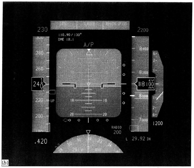
Figure 15.3b Closeup view of the Boeing B-777 primary flight display (courtesy of the Boeing Company).

Figure 15.3c Closeup view of the Boeing B-777 navigation display (courtesy of the Boeing Company).
Modern civil transport aircraft are often equipped with a flight-management computer (FMC), typically part of the flight-management system (FMS), which optimizes the performance and/or flight path of the aircraft in terms of some parameter such as flight time or fuel cost. (Chapter 14.5.7). The most common interface between the crew and the FMC is a control display unit (CDU) like the one for a MD-11 shown in Figure 15.4. In addition to the alphanumeric keyboard, there are special-purpose keys that support the flight-planning and management processes. There are typically three CDUs in the aisle stand of the cockpit, one each for the captain and first officer in the front of the aisle stand, and one at the rear of the aisle stand intended primarily for use by maintenance personnel to operate the on-board maintenance system. This third CDU also is a backup to the other two.
The B-777 aircraft uses a touchpad cursor control for interacting with some of the displays. Immediately below each flight crew CDU is a touchpad that can be used to control a cursor on either the CDU display screen or the electronic library system if installed.

Figure 15.4 MD-11 Control display unit (courtesy of the McDonnell-Douglas Corporation).
Another medium for cockpit/crew interfaces is speech. Speech-interactive systems are of two basic types: synthetic and recognition. Synthetic speech systems have been used for many years to provide aural warnings to the crew such as “Glide slope, glide slope,” and more recently for the traffic alerting and collision avoidance system (TCAS), “Traffic, traffic” (Section 14.8).
Speech is another option for the crew to control the aircraft, particularly under high work load conditions; however, so far it has found only limited application. The major challenge in using speech as a crew/aircraft interface is the same as that in many other speech-interface applications, which is word recognition. Speech systems with a large vocabulary capability are user dependent, which means that the system must be calibrated for each individual user through the generation and use of a pronunciation template. Where speed recognition systems have been tested in aircraft the correct recognition rate is only about in the mid-90% during straight and level flight. In a high-acceleration flight conditions, the rate drops to less than 80%, which is clearly not acceptable.
15.4 POWER
Power is the lifeblood of any avionics system. Historically, avionics designers have always assumed that electrical power would be available in the quality and quantity needed. However, as the performance of electronic devices has improved and avionics are being used in flight critical applications, power has taken on new importance.3
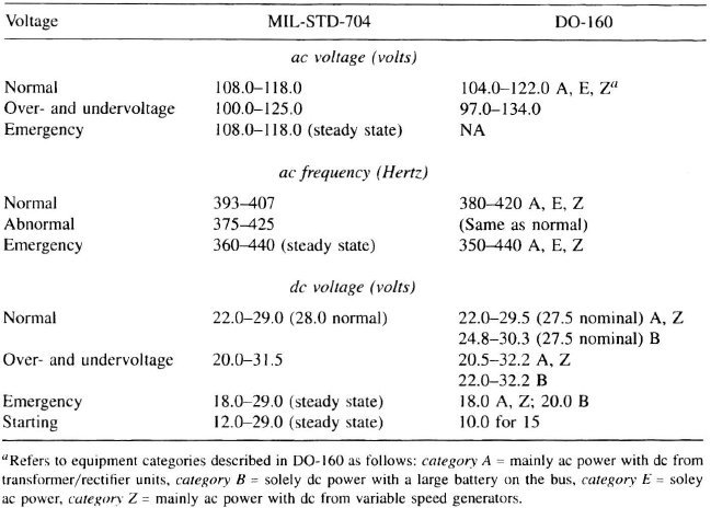
The principal document guiding the design of military aviation power systems is MIL-STD-704 Aircraft Electrical Power Characteristics. This standard levies requirements on the power quality as delivered to the connectors on the avionics equipment. A portion of these requirements is summarized in Table 15.2, along with equivalent requirements from DO-160, Environmental Conditions and Test Procedures for Airborne Equipment, the standard for civil aviation power. Civil avionics power requirements are very similar to those for military avionics, as shown in Table 15.2. DO-160 presents power quality requirements for avionics and describes the laboratory test facilities and procedures for verifying the operation (or survival) of the avionics when energized by power of the stated quality. Like the military power systems, a major driver for civil power systems is continuous availability of power for flight critical functions.
15.5 MAINTENANCE
Maintenance is a major factor in avionics life cycle costs, since much of the life-cycle cost is incurred as maintenance cost after the avionics has entered service. Maintenance costs are driven in large part by the amount of attention maintenance receives early in the design stage. The key drivers in maintenance are well designed built-in test (BIT) of the line replaceable unit (LRU, commonly called a black box) or line replaceable modules (LRMs); clearly written maintenance manuals; easy-to-use maintenance aids, and accessibility, both to replace the LRU and internal to it.
BIT is always a major concern in avionics, since approximately one-half of the avionics LRUs removed from an aircraft that are thought to be faulty are in fact not faulty. A common way of stating this situation is that the mean time between unscheduled removals (MTBUR) is approximately 50% of the mean time between failure (MTBF). One avionics manufacturer has stated a goal of increasing MTBUR to 90% of MTBF for some of the B-777 avionics. Maintenance costs are nearly the same for a LRU removal from service that later checks out to be operational, as for a LRU removal from service that is truly faulty. This is so because of the additional testing that a good LRU must undergo to determine that it is, in fact, good. As a typical design goal, BIT should be able to detect 98% of all possible faults in an LRU and identify 95% of them. Also, the BIT function should be able to test itself.
TABLE 15.2 MIL-STD-704 and DO-160 aircraft power characteristics
Another major consideration is who will be performing the maintenance and where it will be performed. The general lack of well-experienced maintenance personnel, coupled with the frequent need to get the aircraft back into the air as quickly as possible, dictate that maintenance procedures and equipment be easy to use. The availability of notebook computers with large memory capacity and reasonably large displays has led to advanced portable maintenance aids that significantly reduce the troubleshooting time and the unscheduled removals discussed earlier.
15.6 PHYSICAL INTERFACE
Packaging of the avionics is another type of “interface” with the host aircraft. Most modern avionics is packaged in accordance with widely used packaging standards. In commercial transport aircraft and some business jets, the avionics LRUs are designed in compliance with the ARINC 600 Air Transport Avionics Equipment Interface. ARINC 600 establishes standards for the LRU dimensions, cooling air, and connector and tiedown placement. Figure 15.5 shows an ARINC 600 LRU. For any ARINC 600 LRU, the height and depth are constant, 7.64 and 12.75 in., respectively, but the width can vary from 25 to 256 mm in increments of 33.0 mm, depending on the number of printed circuit boards inside.

Figure 15.5 ARINC 600 line replaceable unit.
Military avionics is packaged in a much larger variety of nonstandard LRU designs. The principal approach to standardized packaging for military avionics is the standard electronics module specified in MIL-M-28787 Modules, Standard Electronic, General Specification for. There are several optional sizes described in that specification; however, the one most often selected is size E. Hence, there are frequent references to SEM-E modules in military avionics publications. SEM-E modules have a standard height of 6.68 in. and span (depth when viewed from the front) of 5.88 in. The width (thickness) can range from 0.38 to 0.58 in., in 0.1-in. increments.
Cooling the avionics is often a major issue, since conventional wisdom holds that the lower the operating temperature of the avionics, the lower is the failure rate, or, conversely, the longer is the MTBF.4 For a cooling air inlet temperature of 30°, ARINC 600 requires a flow rate of 136 kg/hr/kw; for 40°C inlet air, the flow rate climbs to 200 kg/hr/kw, where kw is the amount of power being dissipated by the LRU. Another requirement in ARINC 600 is that the equipment must operate for up to 90 minutes without cooling air.5 As a possible indicator of future practice, the B-777 aircraft will use passive cooling, in which the entire avionics bay is cooled and the ambient bay air cools the modules using natural convection flow through air gaps between the modules.
Military avionics is often cooled by the metal rail that grips the printed circuit board card when it is installed in the module. The rail is actively cooled by circulating fluid through it. Also under consideration for advanced military avionics high-power-dissipation cards is the immersion of the entire card directly into a liquid coolant.
Another critical interface with the host aircraft is the mounting alignment of certain types of avionics such as navigation sensors, radio-navigation antennas, radar antennas, and other sensor apertures. Alignment is also critical for HUDs and HMDs, which were discussed earlier in this chapter.
One concern in the realm of physical interfaces is electromagnetic interference (EMI). Modern digital avionics is especially susceptible to EMI because of the higher processor speeds, smaller element sizes on the electronic chips, and the increasing loss of shielding as composite materials replace metals. Because of the complex interaction of electromagnetic fields with the aircraft metallic structure and wiring, EMI effects are difficult to model and predict, although progress is being made using finite element methods in programs operating on high-speed computers. Consequently, many adverse EMI effects are not discovered until the avionics is installed on the host aircraft.
15.7 FUTURE TRENDS
The present trend toward increased integrated avionics and automated cockpits is expected to continue, driven by even higher-speed microprocessors and data buses. Over the next decade, more aircraft functions will be allocated to the avionics, including additional flight critical ones. The avionics will be packaged in modules that fit into a cabinet that provides cooling air, a backplane data bus, power, and EMI protection. Fault tolerance will become a major design feature of avionics to ensure error-free operation for long periods. Enhanced vision systems will be the cornerstone of enhanced situation awareness, leading to safer operations in low-visibility and crepuscular (e.g., twilight) conditions.
In the longer term, distributed avionics architectures may develop in which there will be multiple identical avionics cabinets distributed throughout the aircraft, each of which will be capable of performing all functions, including centralized ones such as maintenance monitoring and recording.
PROBLEMS
15.1. Discuss the advantages of fiber-optic data buses over wire data buses.
15.2. Why is it necessary to determine the data latency for a given data bus configuration?
15.3. State the advantages of liquid crystal displays over cathode-ray tube displays.
1As an example. FAA Advisory Circular 25-11 Transport Category Airplane Electronic Display Systems, requires that there be no more than 0.1-sec latency in displaying aircraft attitude information on cockpit electronic displays. Also it is important to note that typical subsonic large aircraft velocities are over 600 ft/sec, which can generate substantial data latency issues in precision navigation systems.
2One avionics manufacturer has developed a drop-in replaceable LCD horizontal situation indicator (HSI) for the United States Air Force F-15 that is lighter and 100 times more reliable than the original electromechanical design.
3In the X-29 aircraft a loss of power for more than 0.2 sec will result in an unrecoverable attitude requiring immediate ejection by the pilot.
4Some reliability experts doubt the validity of the assumption that higher temperatures, at least within the operating temperature range of most avionics, lead to higher failure rates. They believe instead that the failure rate is coupled to the number of on/off cycles an electronic component or device experiences.
5This requirement is driven by the typical airline route structure, which dictates that an aircraft should be capable of being dispatched with an inoperative cooling system for up to a ![]() -hr flight from a remote “spoke” or feeder airport with limited or no-maintenance capability to an airport where the cooling system can be repaired.
-hr flight from a remote “spoke” or feeder airport with limited or no-maintenance capability to an airport where the cooling system can be repaired.