H¯¯¯(h)=−−−G(h)r,mαmG(h)i,mαm.00−−−G(h)r,mβmG(h)i,mβm.000¯2(m1)×2(nm+1)−−−−−−−−.....−−.....−−−00.G(h)r,nαnG(h)i,nαn−−−00.G(h)r,nβnG(h)i,nβn

si489_e  (7-112)

where h = 1, 5, 7, …, L. For h = 1 the entries are zero.

7.4.5 Harmonic Jacobian Entry Formulas Related to Line Currents

Figure 7.15 shows a typical nonlinear bus i of an n bus system. This ith bus is connected to three other buses, m, k, and l. The nonlinear device connected to bus i demands a complex load current g˜(h)load,isi490_e (referred to the nonlinear bus i) at the hth harmonic frequency.

f07-15-9780128007822
Figure 7.15 Nonlinear bus i.

The total hth harmonic complex current leaving bus i via the lines is

I˜(h)lines,i=I˜(h)k+I˜(h)+I˜(h)m,

si491_e  (7-113a)

I˜(h)lines,i=(V˜(h)iV˜(h)k)y˜(h)ik+(V˜(h)iV˜(h))y˜(h)i+(V˜(h)iV˜(h)m)y˜(h)im,

si492_e  (7-113b)

where ij(h) is the admittance of the line connecting buses i and j evaluated at the hth harmonic frequency. Rearranging terms gives

I˜(h)lines,i=(y˜(h)ik+y˜(h)i+y˜(h)im)V˜(h)iy˜(h)ikV˜(h)ky˜(h)iV˜(h)y˜(h)imV˜m(h),

si493_e  (7-114a)

or

I˜(h)lines,i=(Y¯¯¯(h)bus)iiV˜(h)i+(Y¯¯¯(h)bus)ikV˜(h)k+(Y¯¯¯(h)bus)iV˜(h)+(Y¯¯¯(h)bus)imV˜(h)m,

si494_e  (7-114b)

where (Y¯¯¯(h)bus)ijsi495_e is the (i,j)th entry of the hth harmonic admittance matrix. Because k, l, and m are the only buses connected to bus i (see Fig. 7.15),

I˜(h)lines,i=(rowiofY¯¯¯(h)bus)iiV¯¯¯(h)bus,

si496_e  (7-115)

where V¯¯¯(h)bussi497_e is a complex vector of the hth harmonic bus voltages. Therefore, the mismatch current for the hth harmonic is based on the Kirchhoff current law at bus i:

ΔI˜(h)i=I˜(h)lines,i+G˜(h)load,i=(rowiofY¯¯¯(h)bus)V¯¯¯(h)bus+G˜(h)load,i,

si498_e  (7-116)

where G˜(h)load,isi499_e is the hth harmonic nonlinear complex load current (for bus i), referred to the swing bus:

G˜(h)load,i=G(h)r,i+jG(h)i,i

si500_e  (7-117)

In this equation, the second index i pertains to bus i and the first index i indicates imaginary. Breaking the mismatch current ΔĨi(h) into a real part ΔIr,i(h) and an imaginary part ΔIi,i(h) we get

ΔI(h)r,i=Real{(rowiofY¯¯¯(h)bus)V¯¯¯(h)bus}+G(h)r,i

si501_e  (7-118a)

ΔI(h)i,i=Imag{(rowiofY¯¯¯(h)bus)V¯¯¯(h)bus}+G(h)i,i,

si502_e  (7-118b)

Therefore,

ΔI(h)r,i=I(h)r,i+G(h)r,i=j=1ny(h)ijV˜(h)jcos(θ(h)ij+δ(h)j)+G(h)r,i,

si503_e  (7-119a)

ΔI(h)i,i=I(h)i,i+G(h)i,i=j=1ny(h)ijV˜(h)jsin(θ(h)ij+δ(h)j)+G(h)i,i,

si504_e  (7-119b)

where yij(h) and θij(h) are the magnitude and phase angle of the (i,j)th entry of the hth harmonic admittance matrix, respectively, and |V~(h)jsi505_e| and δj(h) are the hth harmonic voltage magnitude and phase angle of bus j with respect to swing bus.

The entries of the Jacobian matrix corresponding to line currents are submatrices Y¯¯¯(h,h)si506_e (h = 1, 5, …, L). These matrices are defined as

Y¯¯¯(h,h)=(I¯(h))(V¯¯¯(h)).

si507_e  (7-120)

Note that Y¯¯¯(h,j)si508_e = 0 for h ≠ j. The zero terms are due to the fact that the (v-i) characteristics of the nonlinear devices are modeled in the Jacobian matrix using submatrices G¯¯¯(h,j)si509_e.

Y¯¯¯(h,h)=I(h)r,1δ(h)1I(h)i,1δ(h)1I(h)r,nδ(h)1I(h)i,nδ(h)1I(h)r,1V(h)1I(h)i,1V(h)1I(h)r,nV(h)1I(h)i,nV(h)1I(h)r,1δ(h)nI(h)i,1δ(h)nI(h)r,nδ(h)nI(h)i,nδ(h)nI(h)r,1V(h)nI(h)i,1V(h)nI(h)r,nV(h)nI(h)i,nV(h)n,

si510_e  (7-121)

For h = 1 only the last 2(n – m + 1) rows exist because fundamental current balance is not performed for linear load buses. Also for h = 1 the first two columns of the matrix do not exist (are zero) because V˜(1)1si511_e and δ1(1) are known and constant.

The entries of Y¯¯¯(h,h)si512_e are computed from Eq. 7-119 by setting Gr,i(h) and Gi,i(h) to zero:

I(h)r,iδ(h)j=y(h)ijV˜(h)jsin(θ(h)ij+δ(h)j),forh=1,5,,L,

si513_e  (7-122a)

I(h)r,iV˜(h)j=y(h)ijcos(θ(h)ij+δ(h)j),forh=1,5,,L,

si514_e  (7-122b)

I(h)i,iδ(h)j=y(h)ijV˜(h)jcos(θ(h)ij+δ(h)j),forh=1,5,,L,

si515_e  (7-122c)

I(h)i,iV˜(h)j=y(h)ijsin(θ(h)ij+δ(h)j),forh=1,5,,L,

si516_e  (7-122d)

where h and j denote harmonic order and bus number, respectively.

7.4.6 Newton-Based Harmonic Power Flow Algorithm

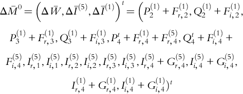
Based on the equations given, the harmonic power flow algorithm is the computation of bus voltage vector Ū for a given system configuration with linear and nonlinear loads. The Newton–Raphson approach (Eq. 7-107) will be used to force the mismatch vector (Eq. 7-101) to zero using the harmonic Jacobian matrix and obtaining appropriate correction terms ΔŪ. Therefore (ξ represents the iteration number),

ΔU¯¯¯ξ=J¯¯1ΔM¯¯¯¯(U¯¯¯ξ),

si517_e  (7-123)

U¯¯¯(ξ+1)=U¯¯¯ξΔU¯¯¯ξ.

si518_e  (7-124)

The solution procedure for the harmonic power flow algorithm is as follows (Fig. 7.16):

f07-16-9780128007822
Figure 7.16 Harmonic Newton-based power flow algorithm.

Step 1: Perform the fundamental load flow analysis (treating all nonlinear devices as linear loads) and compute an initial (approximate) value for the fundamental bus voltage magnitudes and phase angles. Make an initial guess for the harmonic bus voltage magnitudes and phase angles (e.g., 0.1 pu and 0 radians).

Step 2: Compute nonlinear device currents Gr,m(h) and Gi,m(h) (referred to the swing bus) for nonlinear loads.

Step 3: Evaluate ΔM¯¯¯¯(U¯¯¯)si519_e using Eqs. 7-101, 7-102. If it is small enough then stop.

Step 4: Evaluate J¯¯(h)si520_e (Eqs. 7-108 to 7-112 and 7-121) and calculate ΔŪ (Eqs. 7-107 and 7-123) using matrix inversion or forward/backward substitutions.

Step 5: Update Ū (Eq. 7-124).

Step 6: Update the total (fundamental plus harmonic) powers at nonlinear buses (Pjt and Qjt) (Eq. 7-99, Eq. 7-100), and the specified total apparent power or total reactive power (Eq. 7-98), whichever is known.

Step 7: Go to Step 2.

7.4.7 Application Example 7.14: Computation of Harmonic Admittance Matrix

The harmonic power flow algorithm will be applied to the nonlinear power system as shown in Fig. E7.14.1 where all impedances are given in pu at 60 Hz and the base is Sbase = 1 kVA. In order to simplify the problem, the harmonic (v–i) characteristic of the nonlinear load at bus 4 (referred to the voltage at bus 4) is given as

g˜(5)load,4=g(5)r,4+jg(5)i,4,g(5)r,4=0.3(V(1)4)3cos(3δ(1)4)+0.3(V(5)4)2cos(3δ(5)4),g(5)i,4=0.3(V(1)4)3sin(3δ(1)4)+0.3(V(5)4)2sin(3δ(5)4).

si521_e

f07-24-9780128007822
Figure E7.14.1 Four-bus power system with one nonlinear load bus, where n = m = 4, that is, there is one nonlinear bus (bus 4), two linear buses (buses 2 and 3), and the swing bus (bus 1).

It will be assumed that the voltage at the swing bus (bus 1) is V˜(1)1si522_e = 1.00 pu and δ(1)1=0si523_e rad.

The swing bus can be represented by Fig. E7.14.2 at the fundamental frequency. For the 5th harmonic, an of Fig. E7.14.3 represents a short-circuit, and the synchronous machine impedance Z1 is replaced by the (subtransient) impedance Z2 ≈ jX = j0.0001 pu at 60 Hz (see Fig. E7.14.1). In this case the subtransient reactance has been chosen to be very small in order to approximate bus 1 as an ideal bus.

f07-25-9780128007822
Figure E7.14.2 Representation of swing bus (bus 1) for fundamental (h = 1) frequency.
f07-26-9780128007822
Figure E7.14.3 Equivalent circuit of swing bus for the 5th harmonic (h = 5).

Compute the fundamental and 5th harmonic admittance matrices.

Solution to Application Example 7.14

The fundamental bus admittance matrix (X does not exist for fundamental quantities) is computed in Application Example 7.8. The 5th harmonic bus admittance matrix takes into account X and its entries are calculated as follows:

y(5)11=10.01+j(0.025)+10.01+j(0.015)+1j(0.00015)=2029.137pu1.5684rad

si524_e

y(5)12=10.01+j(0.015)=19.612pu1.7681rad

si525_e

y(5)13=0

si526_e

y(5)14=10.01+j(0.025)=9.9503pu1.6704rad

si527_e

y(5)21=y(5)12

si528_e

y(5)22=10.01+j(0.015)+10.02+j(0.085)=22.084pu1.3900rad

si529_e

y(5)23=10.02+j(0.085)=2.4969pu1.62066rad

si530_e

y(5)24=0

si531_e

y(5)31=y(5)13

si532_e

y(5)32=y(5)23

si533_e

y(5)33=10.02+j(0.085)+10.01+j(0.025)=12.445pu1.4811rad

si534_e

y(5)34=10.01+j(0.025)=9.9504pu1.6704rad

si535_e

y(5)41=y(5)14

si536_e

y(5)42=y(5)24

si537_e

y(5)43=y(5)34

si538_e

y(5)44=10.01+j(0.025)+10.01+j(0.025)=19.901pu1.4711rad.

si539_e

Therefore,

Y¯¯¯(5)bus=2029.137pu1.5684rad19.61pu1.7681rad09.9503pu1.6704rad19.61pu1.7681rad22.0847pu1.3900rad2.4969pu1.62066rad002.4969pu1.62066rad12.445pu1.4811rad9.9504pu1.6704rad9.9503pu1.6704rad09.9504pu1.6704rad19.901pu1.4711rad.

si540_e

Note that: yijθij=yij(θij+π).si541_e

7.4.8 Application Example 7.15: Computation of Nonlinear Load Harmonic Currents

For the system of Fig. E7.14.1, assume an initial value for the bus vector Ū0 and compute the fundamental and the 5th harmonic currents injected into the system by the nonlinear load. The computation of the nonlinear load harmonic currents is the initial step of the harmonic load flow algorithm.

Solution to Application Example 7.15

The initial step of harmonic load flow is as follows:

The real and imaginary nonlinear device currents G(1)r,4si542_e and G(1)i,4si543_e – referred to the swing bus – may be computed as follows, where the following powers are referred to the nonlinear bus 4:

P(1)4=V(1)4I(1)4cos(δ(1_4γ(1)4)Q(1)4=V(1)4I(1)4sin(δ(1_4γ(1)4)

si544_e

I4(1) and γ4(1) = δ4(1) – tan−1(Q4(1)/P4(1)) are the magnitude and phase angle of the fundamental nonlinear device current, respectively. The diagram of Fig. E7.15.1 demonstrates the phasor relationships.

f07-27-9780128007822
Figure E7.15.1 Phasor diagram for fundamental quantities, where ɛ(1)4=tan1(Q(1)4/P(1)4)=(δ(1)4γ(1)4)si4_e or δ(1)4=ɛ(1)4+γ(1)4si5_e.

The real part of the fundamental of the nonlinear device current at bus 4 (referred to the swing bus) is

G(1)r,4=I(1)4cosγ(1)4

si545_e

where

I(1)4=P(1)4V(1)4cos(δ(1)4γ(1)4).

si546_e

Thus

G(1)r,4=P(1)4cosγ(1)4V(1)4cos(δ(1)4γ(1)4).

si547_e

Correspondingly one obtains for the imaginary part of the fundamental of the nonlinear device current at bus 4 (referred to the swing bus):

G(1)i,4=P(1)4sinγ(1)4V(1)4cos(δ(1)4γ(1)4).

si548_e

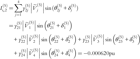
The real and imaginary harmonic (5th) nonlinear device currents are given as (referred to bus 4)

g(5)r,4=0.3(V(1)4)3cos(3δ(1)4)+0.3(V(5)4)2cos(3δ(5)4)g(5)i,4=0.3(V(1)4)3sin(3δ(1)4)+0.3(V(5)4)2sin(3δ(5)4)

si549_e

where δ4(5) is the angle between V˜(5)4si550_e and V˜(1)1si551_e the swing bus voltage, I4(5) is the fifth harmonic current magnitude

I(5)4=(g(5)r,4)2+(g(5)i,4)2

si552_e

and γ4(5) is the phase angle of Ĩ4(5) with respect to the swing bus voltage 1(1).

Assuming bus 1 to be the swing bus (δ(1)1=0radians,V(1)1=1.00pu)si553_e, the solution procedure is as follows.

Step #1 of Harmonic Load Flow. Using the solution vector x¯si554_e of the fundamental power flow analysis (see Application Example 7.13) and assuming harmonic voltage magnitudes and phase angles of 0.1 pu and 0 radians, respectively, the bus vector Ū0 will be

U¯0=(δ(1)2,V˜(1)2,δ(1)3,V˜(1)3,δ(1)4,V˜(1)4,δ(5)1,V˜(5)1,δ(5)2,V˜(5)2,δ(5)3,V˜(5)3,δ(5)4,V˜(5)4,α4,β4)t

si555_e

U¯0=(2.671104,0.9976,2.810103,0.9964,3.414103,0.9960,0,0.1,0,0.1,0,0.1,0,0.1,0,0)t

si556_e

where the angles are measured in radians.

Note that the nonlinear device variables (α4 and β4) are assumed to be zero because there are no device variables defined in this example for the nonlinear load at bus 4.

Step #2 of Harmonic Load Flow. Use Ū0 to compute the nonlinear device currents. With P4(1) = 250 W corresponding to 0.25 pu, Q4(1) = 100VAr corresponding to 0.100 pu, V4(1) = 0.9960 pu, and δ4(1) = –3.414 · 10−3 radians, one gets

ɛ(1)4=tan1(Q(1)4P(1)4)=tan1(0.10.25)=0.3805rad

si557_e

γ(1)4=δ(1)4ɛ(1)4=(0.0034140.3805)=0.38391rad

si558_e

G(1)r,4=P(1)4cos(γ(1)4)V(1)4cos(δ(1)4γ(1)4)=0.25cos(0.38391)0.9960cos(0.003414+0.38391)=0.2514pu

si559_e

G(1)i,4=P(1)4sin(γ(1)4)V(1)4cos(δ(1)4γ(1)4)=0.25sin(0.38391)0.9960cos(0.003414+0.38391)=0.1015pu.

si560_e

The fundamental magnitude of the nonlinear current is

I(1)4=(G(1)r,4)2+(G(1)i,4)2=(0.2514)2+(0.1015)2=0.2711puwithγ(1)4=0.38391rad.

si561_e

The fifth harmonic current components of the nonlinear load current at bus 4 are (referred to bus 4)

g(5)r,4=0.3(V(1)4)3cos(3δ(1)4)+0.3(V(5)4)2cos(3δ(5)4)g(5)i,4=0.3(V(1)4)3sin(3δ(1)4)+0.3(V(5)4)2sin(3δ(5)4).

si562_e

With V4(1) = 0.9960 pu, δ4(1) = –0.003414 rad, V4(5) = 0.1 pu, δ4(5) = 0 rad, one obtains

g(5)r,4=0.3(0.9960)3cos(30.003414)+0.3(0.1)2cos(30)=0.2994pug(5)i,4=0.3(0.9960)3sin(30.003414)+0.3(0.1)2sin(30)=0.003036pu

si563_e

I(5)4=(g(5)r,4)2+(g(5)i,4)2=(0.2994)2+(0.003036)2=0.2994pu

si564_e

ɛ(5)4=tan1(g(5)i,4g(5)r,4)=0.01014rad.

si565_e

Therefore, the fifth harmonic currents at bus 4 referred to the swing bus are G(5)r,4=I(5)4cosγ(5)4si566_e and G(5)i,4=I(5)4sinγ(5)4si567_e.

The phasor diagram for the 5th harmonic is shown in Fig. E7.15.2, where the angles are

δ(5)4=ɛ(5)4+γ(5)4

si568_e

or

γ(5)4=δ(5)4ɛ(5)4=0ɛ(5)4=0.01014rad

si569_e

resulting in G(5)r,4si570_e = 0.2994 pu and G(5)i,4si571_e = –0.003036 pu.

f07-28-9780128007822
Figure E7.15.2 Phasor diagram for 5th harmonic.

These nonlinear currents referred to the swing bus are about the same as those referred to bus 4 because the angle γ4(5) is very small for this first iteration.

Note that

P(1)4=I(1)4V(1)4cos(δ(1)4γ(1)4)=0.27110.9960cos(0.003414+0.38391)=0.250puQ(1)4=I(1)4V(1)4sin(δ(1)4γ(1)4)=0.27110.9960sin(0.003414+0.38391)=0.100pu

si572_e

are as expected. Correspondingly,

P(5)4=I(5)4V(5)4cos(δ(5)4γ(5)4)=0.29940.1cos(0+0.01014)=0.029994puQ(5)4=I(5)4V(5)4sin(δ(5)4γ(5)4)=0.29940.1sin(0+0.01014)=0.000304pu.

si573_e

Therefore, the total injected real and reactive powers at the nonlinear bus 4 are

Pt4=P(1)4+P(5)4=0.250pu+0.02994pu=0.27994puQt4=Q(1)4+Q(5)4=0.100pu+0.000304pu=0.100304pu.

si574_e

7.4.9 Application Example 7.16: Evaluation of Harmonic Mismatch Vector

Using the results of Application Example 7.15, evaluate the mismatch vector for the system of Fig. E7.14.1.

Solution to Application Example 7.16

Step #3 of Harmonic Load Flow. Evaluation of the mismatch vector

ΔM¯0=(ΔW¯,ΔI¯(5),ΔI¯(1))t=(P(1)2+F(1)r,2,Q(1)2+F(1)i,2,P(1)3+F(1)r,3,Q(1)3+F(1)i,3,Pt4+F(1)r,4+F(5)r,4,Qt4+F(1)i,4+F(5)i,4,I(5)r,1,I(5)i,1,I(5)r,2,I(5)i,2,I(5)r,3,I(5)i,3,I(5)r,4+G(5)r,4,I(5)i,4+G(5)i,4,I(1)r,4+G(1)r,4,I(1)i,4+G(1)i,4).

si575_e

To compute these mismatches use equations Eqs. 7-80 and 7-81

ΔPi=Pi+Fr,i=Pi+j=1nyijV˜jV˜icos(θijδj+δi)

si576_e

ΔQi=Qi+Fi,i=Qi+j=1nyijV˜jV˜isin(θijδj+δi)

si577_e

and Eqs. 7-119a,b

ΔI(h)r,i=I(h)r,i+G(h)r,i=j=1ny(h)ijV˜(h)jcos(θ(h)ij+δ(h)j)+G(h)r,i

si578_e

ΔI(h)i,i=I(h)i,i+G(h)i,i=j=1ny(h)ijV˜(h)jsin(θ(h)ij+δ(h)j)+G(h)i,i.

si579_e

Hence,

ΔP(1)2=P(1)2+F(1)r.2=P2+y21V1V2cos(θ21δ1+δ2)+y22V2V2cos(θ22δ2+δ2)+y23V3V2cos(θ23δ3+δ2)+y24V4V2cos(θ24δ4+δ2)=0.0170pu

si580_e

ΔQ(1)2=Q(1)2+F(1)i,2=Q2+y21V1V2sin(θ21δ1+δ2)+y22V2V2sin(θ22δ2+δ2)+y23V3V2sin(θ23δ3+δ2)+y24V4V2sin(θ24δ4+δ2)=0.083pu

si581_e

ΔP(1)3=P(1)3+F(1)r,3=P3+y31V1V3cos(θ31δ1+δ3)+y32V2V3cos(θ32δ2+δ3)+y33V3V3cos(θ33δ3+δ3)+y34V4V3cos(θ34δ4+δ3)=0.00325pu

si582_e

ΔQ(1)3=Q(1)3+F(1)i,3=Q3+y31V1V3sin(θ31δ1+δ3)+y32V2V3sin(θ32δ2+δ3)+y33V3V3sin(θ33δ3+δ3)+y34V4V3sin(θ34δ4+δ3)=0.00192pu

si583_e

ΔPt4=Pt4+F(1)r,4+F(5)r,4=Pt4+j=14y4jV(1)jV(1)4cos(θ4jδ(1)j+δ(1)4)+j=14y(5)4jV(5)jV(5)4cos(θ(5)4jδ(5)j+δ(5)4)=Pt4+y41V(1)1V(1)4cos(θ41δ(1)1+δ(1)4)+y43V(1)3V(1)4cos(θ43δ(1)3+δ(1)4)+y44V(1)4V(1)4cos(θ44δ(1)4+δ(1)4)+y(5)41V(5)1V(5)4cos(θ(5)41δ(5)1+δ(5)4)+y(5)43V(5)3V(5)4cos(θ(5)43δ(5)3+δ(5)4)+y(5)44V(5)4V(5)4cos(θ(5)44δ(5)4+δ(5)4)=0.037pu

si584_e

ΔQt4=Qt4+F(1)i,4+F(5)i,4=Qt4+j=14y4jV(1)jV(1)4sin(θ4jδ(1)j+δ(1)4)+j=14y(5)4jV(5)jV(5)4sin(θ(5)4jδ(5)j+δ(1)4)=Qt4+y41V(1)1V(1)4sin(θ41δ(1)1+δ(1)4)+y43V(1)3V(1)4sin(θ43δ(1)3+δ(1)4)+y44V(1)4V(1)4sin(θ44δ(1)4+δ(1)4)+y(5)41V(5)1V(5)4sin(θ(5)41δ(5)1+δ(5)4)+y(5)43V(5)3V(5)4sin(θ(5)43δ(5)3+δ(5)4)+y(5)44V(5)4V(5)4sin(θ(5)44δ(5)4+δ(5)4)=0.188pu

si585_e

I(5)r,1=j=14y(5)1jV˜(5)jcos(θ(5)1j+δ(5)j)=y(5)11V˜(5)1cos(θ(5)11+δ(5)1)+y(5)12V˜(5)2cos(θ(5)12+δ(5)2)+y(5)13V˜(5)3cos(θ(5)13+δ(5)3)+y(5)14V˜(5)4cos(θ(5)14+δ(5)4)=0.201pu

si586_e

I(5)i,1=j=14y(5)1jV˜(5)jsin(θ(5)1j+δ(5)j)=y(5)11V˜(5)1sin(θ(5)11+δ(5)1)+y(5)12V˜(5)2sin(θ(5)12+δ(5)2)+y(5)13V˜(5)3sin(θ(5)13+δ(5)3)+y(5)14V˜(5)4sin(θ(5)14+δ(5)4)=201.98pu

si587_e

I(5)r,2=j=14y(5)2jV˜(5)jcos(θ(5)2j+δ(5)j)=y(5)21V˜(5)1cos(θ(5)21+δ(5)1)+y(5)22V˜(5)2cos(θ(5)22+δ(5)2)+y(5)23V˜(5)3cos(θ(5)23+δ(5)3)+y(5)24V˜(5)4cos(θ(5)24+δ(5)4)=0.000255pu

si588_e

I(5)i,2=j=14y(5)2jV˜(5)jsin(θ(5)2j+δ(5)j)=y(5)21V˜(5)1sin(θ(5)21+δ(5)1)+y(5)22V˜(5)2sin(θ(5)22+δ(5)2)+y(5)23V˜(5)3sin(θ(5)23+δ(5)3)+y(5)24V˜(5)4sin(θ(5)24+δ(5)4)=0.000620pu

si589_e

I(5)r,3=j=14y(5)3jV˜(5)jcos(θ(5)3j+δ(5)j)=y(5)31V˜(5)1cos(θ(5)31+δ(5)1)+y(5)32V˜(5)2cos(θ(5)32+δ(5)2)+y(5)33V˜(5)3cos(θ(5)33+δ(5)3)+y(5)34V˜(5)4cos(θ(5)34+δ(5)4)=0.000104pu

si590_e

I(5)i,3=j=14y(5)3jV˜(5)jsin(θ(5)3j+δ(5)j)=y(5)31V˜(5)1sin(θ(5)31+δ(5)1)+y(5)32V˜(5)2sin(θ(5)32+δ(5)2)+y(5)33V˜(5)3sin(θ(5)33+δ(5)3)+y(5)34V˜(5)4sin(θ(5)34+δ(5)4)=0.0000082pu

si591_e

I(5)r,4+G(5)r,4=j=14y(5)4jV˜(5)jcos(θ(5)4j+δ(5)j)+G(5)r,4=y(5)41V˜(5)1cos(θ(5)41+δ(5)1)+y(5)43V˜(5)3cos(θ(5)43+δ(5)3)+y(5)44V˜(5)4cos(θ(5)44+δ(5)4)+G(5)r,4=0.2996pu

si592_e

I(5)i,4+G(5)i,4=j=14y(5)4jV˜(5)jsin(θ(5)4j+δ(5)j)+G(5)i,4=y(5)41V˜(5)1sin(θ(5)41+δ(5)1)+y(5)43V˜(5)3sin(θ(5)43+δ(5)3)+y(5)44V˜(5)4sin(θ(5)44+δ(5)4)+G(5)i,4=0.00325pu

si593_e

I(1)r,4+G(1)r,4=j=14y(1)4jV˜(1)jcos(θ(1)4j+δ(1)j)+G(1)r,4=y41V˜(1)1cos(θ(1)41+δ(1)1)+y43V˜(1)3cos(θ(1)43+δ(1)3)+y44V˜(1)4cos(θ(1)44+δ(1)4)+G(1)r,4=0.0027pu

si594_e

I(1)i,4+G(1)i,4=j=14y(1)4jV˜(1)jsin(θ(1)4j+δ(1)j)+G(1)i,4=y41V˜(1)1sin(θ(1)41+δ(1)1)+y43V˜(1)3sin(θ(1)43+δ(1)3)+y44V(1)4sin(θ(1)44+δ(1)4)+G(1)i,4=0.0054pu.

si595_e

The mismatch vector ΔM¯¯¯¯0si596_e is now

ΔM¯¯¯¯0=(ΔW¯¯¯¯,ΔI¯(5),ΔI¯(1))t=(P(1)2+F(1)r,2,Q(1)2+F(1)i,2,P(1)3+F(1)r,3,Q(1)3+F(1)i,3,Pt4+F(1)r,4+F(5)r,4,Qt4+F(1)i,4+F(5)i,4,I(5)r,1,I(5)i,1,I(5)r,2,I(5)i,2,I(5)r,3,I(5)i,3,I(5)r,4+G(5)r,4,I(5)i,4+G(5)i,4,I(1)r,4+G(1)r,4,I(1)i,4+G(1)i,4)t

si597_e

or

ΔM¯¯¯¯0=(0.0170,0.083,0.00325,0.00192,0.037,0.188,0.201,201.98,0.000255,0.000620,0.000104,0.0000082,0.29960.00325,0.0027,0.0054)t.

si598_e

Note that for a mismatch residual of 0.0001 pu the solution has not converged yet.

7.4.10 Application Example 7.17: Evaluation of Fundamental and Harmonic Jacobian Submatrices

Using the results of Application Examples 7.15 and 7.16, evaluate the Jacobian matrix for the system of Fig. E7.14.1.

..................Content has been hidden....................

You can't read the all page of ebook, please click here login for view all page.
Reset