This chapter discusses how to look at a Revit model using the views set up in the default template, as well as how to create new views. We'll explore how to create plan, section, elevation, and 3D views. This chapter also explores how to create simple schedules quickly and how to customize a schedule to show a wide range of information available in a building information model.
We will cover the following topics:
Visualizing a Revit model
Creating views
Working with views
Schedules
In Chapter 2, "Getting Acquainted — Interface and File Types," we discussed the basics of the Revit interface. Let's now dive into the primary data visualization components of Revit. You'll notice immediately that Revit is designed with architectural drawing conventions in mind. The various views that Revit generates should be familiar: floor plans, sections, elevations, details, perspectives, and even schedules. Each of these is a way to display the building model in what Revit calls views. The view typology follows a long tradition; however, the act of creating views with Revit is quite new and can be very different from traditional drafting and CAD practices.
There is an important difference between Revit and CAD applications to keep in mind as we delve into documenting and viewing a building information model. In Revit, views are dynamic, live snapshots taken from the same database that you created as you built your model. In CAD, views are represented by line drawings created manually from scratch and are independent of one another. Each drawing is a manually generated artifact. In Revit, you build your building by making a digital model. Then when you need to create a view, be it plan, section, or whatever, you don't need to create or redraw; it's already there — available to you. It is as if you're taking a snapshot of the very same 3D model from various vantage points.
As you learned in Chapter 1, "Understanding BIM," in Revit a wall drawn in any view is represented in other views automatically. For example, the wall is drawn in plan view, and it shows automatically in 3D, section, and elevation view. There is no need to draw the wall multiple times in separate views as you'd need to in CAD. This feature is incredibly powerful because it allows you to rapidly generate your building geometry and have all the information necessary to begin laying out a drawing set much earlier in the design process. From an early stage, you have enough information to generate plans, sections, elevations, and details, and place them onto sheets for documentation. From that point forward, sheets on which such views have been placed will update automatically as the design progresses and moves through the many changes and iterations that are typical in an architecture project. When the design solidifies, you'll add the necessary level of construction detail and annotations to your views.
Views are best understood as live snapshots of the same 3D model taken from various vantage points. There are many view types in Revit: plans, sections, elevations, schedule tables, lists, 3D views, and sheets. These are easily recognized and organized in the Project Browser. Each view type provides control over values such as view depth, scale, display style, visibility of elements, and level of detail. Right-clicking any view in the Project Browser lets you access the properties of that view and change any of these values. As you'll see, view properties lets you be extremely versatile in how you represent a view.
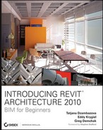
The majority of the tools for view creation can be found under the View tab in the Ribbon (shown in Figure 3.1).
As do all the other Ribbon tabs, the View tab has three states: Minimized to Tabs, Minimized to Panel Titles, and Full Ribbon. You can switch among these by selecting the little arrow at the far right of the tab. The Minimized to Panel Titles state offers four view panels: Graphics, Create, Sheet Composition, and Windows (see Figure 3.2). There you'll find tools for controlling the view graphics, creating new views, managing and modifying the current view, and switching views.

There are some additional ways to create views, which we'll be exploring throughout this chapter. Any view can be preset using project templates; this assures consistency across teams and projects when new projects are started. When you use Revit's default templates, a number of views are already established when you start a new project. As you develop your own graphic standards, you'll be able to create your own starting project templates. However, in this book, we will primarily be using the default templates. Customization of templates is covered extensively in the book Mastering Revit Architecture 2010 (Sybex, 2009).
As new views are created, they appear instantly in the Project Browser. When you create new views or delete views, they're added to or removed from this list automatically. Double-clicking on the name of any view in the Project Browser opens that view in the drawing area and makes it active. An active view can be closed later using the Close button in the upper-right corner of the view. Note that this will not delete the view — it will just close it in the drawing area. To delete a view, use the right-click menu when the mouse is over the view name in the Project Browser, or delete the view symbol (such as the section mark or elevation tag) in another view where the mark is available.
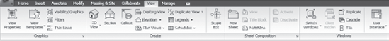
In addition to using the Project Browser, you can use view reference graphics, including section marks, elevation tags, and levels, as hyperlinks to navigate between views. When a view such as a section is created, the section view tag in Revit will be displayed in blue in other views — floor plans and other sections. You can double-click this blue tag to go directly to the view it references. You must double-click the arrow (in the case of elevations) or the flag (for sections and callouts) to open the view. Figure 3.3 shows that tag in black and white.
Note
To toggle through multiple open views, press Ctrl+Tab on the keyboard. To view all open views, go to the Switch Windows menu (under the Windows panel) — all available views will be listed.
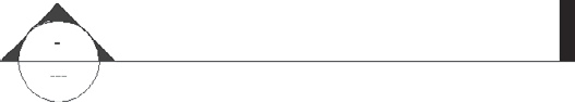
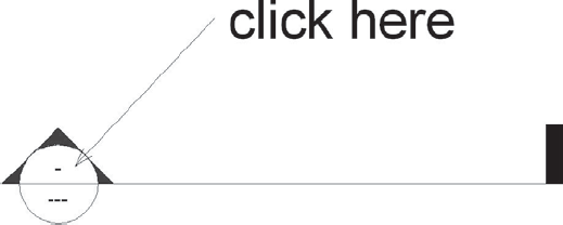
Make sure you double-click within the blue section tag to open the corresponding view (see Figure 3.4). Double-clicking the section line will not open the associated section. You can also use the right-click menu when hovering your mouse over view tags, and choose Go to View (or Go to Specific View when one unique link is available) from the context menu to navigate to a new view.
Note
The hyperlinking of section and elevation tags via double-clicking works only when they are not selected or highlighted. If they're selected (highlighted blue in Revit), no matter how many times you double-click, it won't lead you to another view.
This section discusses a few tasks and challenges you may encounter in your first Revit projects when adding or manipulating views.
Let's start with the first view you'll typically use: a plan view. In Revit, the default plan view is referred to as a Level 1 view and is organized under Floor Plans in the Project Browser. A level typically represents one story in a building, but as you'll see later, a level can also be used to reference the position or height of other elements (split levels, roof edges, and so on). Levels are typically created for each story in the building model.
You can select the Level command from the Datum panel under the Home tab (Figure 3.5). When selected, this command allows you to draw a level using two mouse clicks to define the start point and endpoint of the level graphics — this will add a new level and plan view to the model. It's important to note that the Level command is disabled unless you're actively in an elevation or section view.

To create a level using the Level tool, you have to be in section or elevation view. The Level tool will be grayed out in any other view. Select the Level tool, click on a point that will define the height of the level, and then drag the mouse horizontally to click a second point and thus complete the command. The interaction is similar and as simple as drawing a line but will create a 3D level (story) in the project. When a level is drawn, Revit automatically generates a floor plan and a reflected ceiling plan for that level, and lists them in the Project Browser. To add another story, repeat the process.
You can also create a level by copying an existing one. If you are starting with a default Revit template, usually at least two levels are predefined. To create additional levels, open a section or elevation view; select the level line in the view; and, using the Copy command, copy the existing level, thus creating a new one.

Copied levels react differently from those drawn with the Level command. The critical difference is that the level symbol will appear black instead of blue. This isn't just a graphic difference: the copied level doesn't automatically create a new view (you will see in the Project Browser that no new plan has been added); it only gives you another level graphic in the project that shows in elevation or in section. This behavior is intentional, and it's useful when you need another benchmark in elevation to show heights or want to associate geometry to a level, but you don't necessarily want to generate an associated plan view. A good example is the top of a parapet wall.
What do you do when you have created a level using the copy method and it isn't associated with a plan view, and you later decide that you want it to become a plan view? It's not too late. Go to View tab and under the Create panel, select Plan Views/Floor Plan. A dialog box opens that allows you to select a level and create a new floor plan based on that level (Figure 3.6). Check Do not duplicate existing views at the bottom of the dialog box. (This process is the same for ceiling plans.) The level symbol will then change to blue, indicating that it is a hyperlink to a plan view.
What happens when you want to create a new view based on an existing floor plan? Say you already have a design plan of Level 1, but also need a presentation plan and a fully annotated plan for your documentation set. You can achieve this in Revit by duplicating views. To duplicate a view, right-click the view's name in the Project Browser (Level 1 for example), and choose Duplicate View from the context menu (see Figure 3.7).
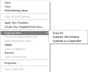
Each command on the Duplicate View submenu makes a duplicate view of the model from the same vantage point. There are three different ways to duplicate a view:
- Duplicate
Makes a duplicated view in which only the model data of that view is copied. This can be useful when you don't wish to copy any tags, dimensions, or annotations from one view to the next. Keep in mind that the model is not copied — you're just creating a duplicate view of the model without bringing along any 2D graphics.
- Duplicate with Detailing
Makes a copy of the model data and any 2D information (such as text, dimensions, or keynotes) in the view. When this method is used, annotations and detailing that are added or edited in the original view after the duplication aren't propagated in the duplicated view. Only model-data modifications are propagated in the duplicated view. The copied annotations are not linked.
- Duplicate as a Dependent
Not only creates a duplicate of all the model and drafting data, but also creates a dependency between the detailing information of the duplicate view and the original view. When this type of duplication is used, changes of both model (3D) and drafting (2D) elements in the original view will propagate in the duplicate view. A use case for this type of duplication would be a project with a big floor plate that you need to split into separate segments for printing. Another one would be a situation where you need to place the same view on multiple sheets.
Note
Dependent views created with the third method (Duplicate as a Dependent) must always remain in the same scale as the original.
Revit provides many types of views for documenting and representing your building designs. This section lists the commonly used views.
All plan views are horizontal slices through the building. Each plan shows the model as cut but can also show information above and below the cut. To control how the plan is represented, a view range is defined. This is a combination of settings that will help you specify exactly what you need when creating a floor plan. Most of the time, Revit's default settings are sufficient. However, there are situations in which you may want (or need) to modify the view range settings to get correct representation.
When working in a modeling environment, a plan view is nothing but a horizontal slice of your building. Architects slice the building at what is called a cut plane. The standard height for a cut plane varies slightly in different regions, but it usually is about 4′–0″ (1.20m). So far, so good. But once you cut the building, how deep do you want to see? Only to the first floor your eyes hit? Or do you need to see beyond that? How do you want to represent the objects below the cut plane? Hidden? Cut through? Dashed? What about the objects above you? Do you want to see the beams above your cut height dashed? Or not at all? This is where the view range options come in handy.
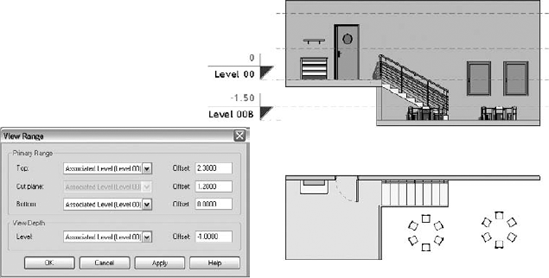
The View Range options are applicable only to floor and ceiling views. Modifying these options influences the visibility and appearance of the elements in the plan or ceiling views of the project. To access the View Range dialog box, shown in Figure 3.8, right-click in the drawing area and choose View Properties → Edit (under Visibility/Graphic Overrides) → View Range.

The following list describes the Primary Range features in the View Range dialog box (see Figure 3.9). These features can be a little complex to understand initially, but as you modify them and see the results in your model, they will become easier to understand.
- Top plane
The top plane defines the uppermost plane above the cut plane up to which elements will be considered. If an element is above the cut plane but still in the primary range (partially or fully), the element is visible in the plan view as if it were seen from below the element.
- Cut plane
The cut plane defines the height at which the 3D elements of the model are physically cut, as shown in Figure 3.10.
- Bottom plane
By default, the bottom plane is coincident with the view depth plane, but it doesn't have to be. If an element is below the cut plane and is wholly in the primary range, it's still shown. Note that only a few Revit elements are considered here: windows, furniture systems, and generic models.
- View depth
View depth defines the extent to which you want to view what is below the cut plane.
Various combinations and values set in the View Range dialog box will produce different ways of representing the plan and ceiling views of the model.

Figure 3.11. A split level requires specific view range settings to display what you need in plan view.
Figure 3.11 is a model of a simple space that we will use to explain the view range. You can find this model on the book's web page. We have chosen a split-level example to show you the power of various settings and how they affect the display of the view range parameters. Note that the furniture and the chairs belong to the Furniture category. The wall shelf belongs to the Furniture Systems category.
Figures 3.12 through 3.14 demonstrate the use of the view range and illustrate how different settings for the bottom plane and cut plane result in different plan view displays.
Revit doesn't cut all 3D elements. When you cut furniture, regardless of the cut plane, the furniture is not cut. In addition, some Revit families are never cut. To understand which Revit elements are cuttable and which are not, choose the Manage tab and click Project Settings → Settings → Object Styles. Note that some elements are grayed out in the Cut column (see Figure 3.15). These objects aren't cuttable, meaning they are not affected by a change of cut height.
- Floor plans
Floor plans are horizontal slices through the building and are associated with levels. These views typically cut the model at 4′ (1.2 m) above the level line.
- Ceiling plans
Ceiling-plan views behave in a similar fashion to floor plans, with the exception that they give a view upward to the ceiling of a level. (You look up instead of down as in a standard floor plan.)
- Site plans
Site plans by default are at 1″-20′ (1:250) scale and are views from above your model. The site plan typically shows the physical and topographic features of the model and doesn't show certain annotations that normally would not appear at scales greater than 1/16″-1′ 0″ (1:200).
- Area plans
Area plans can be used for gross area, rentable, or Building Owners and Managers Association (BOMA) area calculations, to name a few. To create one of these types of plans, click the Home tab and under the Room and Area panel select Area and then Area Plan. Area plans are most effective when you have areas that span multiple rooms.
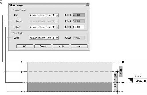

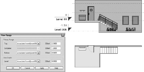
Figure 3.12. The lower level is not displayed at all. The bottom plane and the view depth have been set to Level 00.
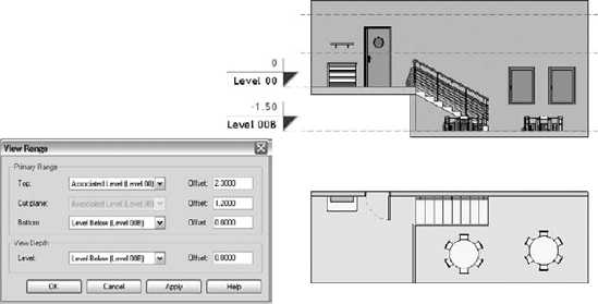
Figure 3.13. The lower level is displayed along with the furniture placed on it. The bottom plane is set to Level 00B and the view depth is set to the same value as the bottom plane (Level 00B).

A callout is a detail view that can be placed in plan, section, or elevation views. For example, if you have a plan view of a kitchen and you want to create another plan view that represents only part of the kitchen at a larger scale to show more detail, you use this command. Callouts are used to show a larger-scale cutout of a view that is dependent on the parent view from which it was placed. This means that if the parent view is deleted, any callout view or views dependent on that parent view will also be deleted. There are two possible types of callout views for floor plans (as shown in the Type Selector when you select the Callout tool): Floor Plan and Detail View. Similarly, for sections, you can choose either Section or Detail View. Once you make a choice, the new callout will show up in the Project Browser, either under Floor Plans (Sections) with the prefix Callout before the view name, or under the Detail Views folder.
Elevations show your model projected onto a vertical plane, so you can evaluate and annotate building façades and interior wall elevations. Elevations are created by placing elevation tags into your model. These are orthogonal projection views (of the exterior façades of the building or of interior elevations). What's great about Revit is that when you insert an elevation tag, it dynamically positions itself perpendicular to any wall. This speeds up the process of making as many elevations as you need, even in projects that have complex, nonorthogonal floor plans. Once an elevation has been placed, you can duplicate any elevation by right-clicking the view name in the Project Browser and choosing Duplicate View → Duplicate. This will make a new nondependent elevation view.
Note
Try drawing a few nonorthogonal walls. From the View tab, under the Create panel, select Elevation and start placing the elevation tag at various places around the walls, moving the mouse around the plan. See how the elevation tag orients itself automatically according to the wall that it references or one that is nearby. If you have a series of walls at different angles to each other, it selects the one most nearly perpendicular to it.

Figure 3.16. A highlighted elevation tag. Note that the active elevations' associated boxes are checked.
Each elevation symbol is capable of creating four elevation views at once, each facing a different direction. This is designed for interior elevations. If you place an elevation symbol in the middle of a room, by inserting the tag and then highlighting the center of it, you see check boxes that can be used to activate the other elevations. Check or uncheck one of the boxes to turn the elevation on or off (see Figure 3.16).
Note
Revit understands the differences between interior and exterior elevations. When creating interior elevations (placing an elevation tag in the middle of a room), Revit draws the elevation of the room in a way that it cuts it where the bounding walls, floors, and ceilings are located. The interior elevation tags in Revit are capable of generating four orthogonal elevations at a time. To do that, select the tag and check all four sides of the elevation arrows.
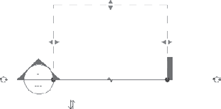
Selecting an activated elevation arrow gives you additional options and displays the width and depth of the elevation. In Figure 3.17, the bar represents the width of the elevation, and the dashed line shows the depth. Both of these properties can be modified either in plan or in the actual elevation. The bar also determines the start plane of the cut and may be moved independently from the elevation graphic.


You can double-click any of the elevation arrows to navigate directly to the corresponding elevation view, or you can open the elevation views from the Project Browser. Once the elevation is placed on a sheet, the sheet number appears inside the elevation box (Figure 3.18), and the view number appears in the elevation arrow. Deleting the elevation tag deletes all the corresponding elevations from the model.
Sections show a vertical slice through the model. The properties of section tags are similar to those of elevation tags, except the cut plane of the section graphic cannot be moved independently from the section graphic (as with elevation symbols). The view width and depth are defined by the dashed lines when a section is selected, as in the elevation. Use the opposing arrow drag controls to adjust the crop boundary of the section (Figure 3.19).
You often need a jointed section cut through a project — for example, when you want to cut through a building but want to jog the section line to pass through a staircase that isn't in the cut line of the initially desired section. To accommodate this, the Section tool has the capability of splitting so that it allows for staggered section lines.
To stagger a section line, first draw a section line where you need to establish a view. Next, select the section, and choose Split Segment from the Section panel of the Modify Views tab. This enables the Split tool and allows you to split the section line at any point. Note that now each segment of the section cut can be adjusted for location and depth. Grab a portion of a section line that you've segmented, and move it up or down to achieve the desired position. A section line can be cut multiple times if need be.
Note
For best performance, be sure to limit the depth of your section and elevation cuts only to what you really want to see. For example, if you are cutting a wall section, there is no reason to set the section depth past the back wall of the room in which you are cutting the section. Revit will calculate all of the information whether or not you see it, so make your section depth as shallow as possible in order to gain in performance and not force Revit to calculate what you do not need to see.
Drafting views are 2D views specifically designed to show information that is not generated directly from the model. They're usually used to show standardized details or information that is typical of a certain area but doesn't necessarily have a connection with the model. Drafting views can also be used to display detailed 2D information about something in the model.
A range of 2D details and elements by various manufacturers is available on the Web, usually in DWG or DXF format. You can use these resources to enrich your Revit model. You can also reuse 2D details from previous CAD projects. Drafting views let you import CAD files of standard details or create 2D details by drawing with drafting tools such as lines and fill patterns.
It is important to understand that drafting views created separately from the model or imported can be referenced in the model and linked to a callout so your drawing sheets always maintain a parametric relationship to their associated details. You should also understand that using the Callout Detail tool allows you to create dynamic details that are generated out of the model with 2D drafting elements overlaid on top. Unlike drafting details, these details are connected with the model elements, so any model changes are reflected in the details.
Drafting views can be inserted onto sheets and can also be referenced to sections or elevations as a similar (SIM) condition. To reference a drafting view to a model, follow these steps:
Create your new drafting view: switch to the View tab, and in the Create panel select Drafting View.
Import a DWG file, or use detail lines, filled regions, and other drafting tools from the Annotate tab to create the 2D detail.
Switch to a view where you want to indicate a callout that will reference this newly created drafting view.

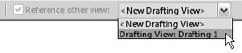
Prior to drawing the callout bubble in the model where the detail explains the condition, from the Options bar check the Reference Other View option in the Options bar and choose the drafting view you just created (see Figure 3.20). Now draw the callout bubble where you wish the drafting view to be referenced.
The resulting reference brings you to more detailed information about the portion of the model that you describe in the drafting view.
As discussed in Chapter 1,"Understanding BIM," you don't need to model every detail of the building. Each project needs to define an acceptable level of detail to model, based on the project parameters.
We've just covered the main types of views in Revit. Now let's take a look at some additional tools that fine-tune how we look at the model.
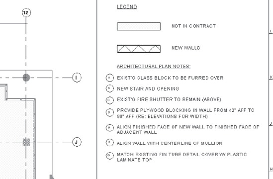
Legends are a special type of view in Revit that allow you to place graphic representations of elements in the model to explain the symbology used in the project. Examples include a key to symbols in a site plan; typical wall, door, or window types used in a project; or demolition notes on a title block. Unlike all other views, which you can place only once on a sheet, legends are used for views you want to have appear on multiple sheets. Legends are 2D elements derived from the components used in your project. Elements in a legend have no effect on scheduling quantities of elements. For example, adding a door symbol to a legend view will not increase the number of instances of that door in the overall project and thus won't be reflected in the schedule of the door totals. This is one of Revit's more sophisticated and unique features (see Figures 3.21 and 3.22).
To create a legend view, first click the View tab. On the Create panel, click the Legends button and select Legend. You can then give the legend view a name and associated scale, and you will be presented with an empty view window. To start creating the legend and add content to this view, go to the Annotate tab, and under the Detail panel, click the Component button. Then select Legend Components and start generating the legend.
Note
Legends are the only view type in Revit that can be placed on multiple sheets.

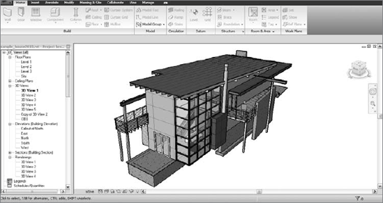
Axonometric views of the entire project model can be generated by clicking the 3D button (the house icon) on the Quick Access toolbar located at the top left of the application (Figure 3.23) or by selecting the 3D View tool, located on the Create panel of the View tab.
Figure 3.23. Click the 3D button on the Quick Access toolbar to create a 3D view of the model on the fly.
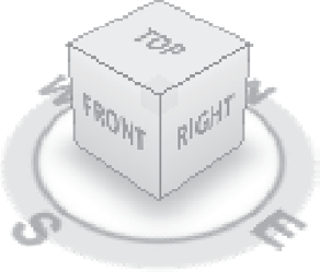
Once a 3D view is created, you can orbit around the model to get a visual feel for your building. Once you like the view, rename it so it gets stored under a recognizable name in the Project Browser, by right-clicking on the {3D} name; that way, you can easily come back to it later. Once you've renamed the default {3D}, any time you click the 3D button from the toolbar, it will create a new default {3D} view for you to use again (Figure 3.23). To orbit and pan around the model, use the ViewCube (see Figure 3.24) that appears in the top-right corner of any 3D view. Clicking on faces, edges, and corners of the ViewCube will spin the model (actually the camera) accordingly.
The Steering Wheel is another tool that helps you navigate through the model. By default, it is positioned on the far right of the drawing area, just below the ViewCube.
Details of how to use the mouse, the ViewCube, and the Steering Wheel are covered in Chapter 2, "Getting Acquainted — Interface and File Types."
The visibility of these navigation tools can be controlled from the View toolbar. In the Windows panel, under User Interface, you specify whether you want a tool to be visible or not.
Figure 3.25 shows an axonometric view of a house.

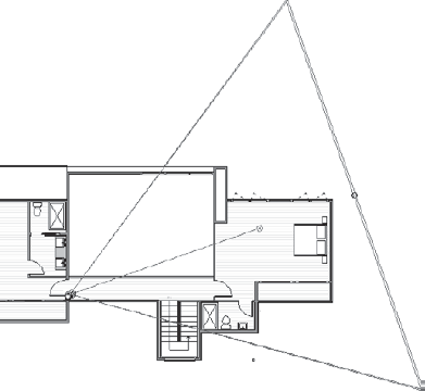
Another type of 3D view is the perspective view (Figure 3.26). You create a perspective view by using the Camera tool. Once created, these views also appear under the 3D Views folder in the Project Browser. When creating perspective views, be sure to give your views unique and descriptive names, as you will find yourself creating many perspective views in a project. This approach will save time later when you are hunting for views to open or place on sheets.
To create a perspective (camera) view, you will need to place a camera in a view. The typical approach is to position the camera in a floor plan view. By default, the camera view is 5′–6″ (1,750 mm) above the floor and looks straight ahead.
To create a camera view, follow these steps:
Make sure you're in a floor plan view. Click the View tab, and in the Create panel, under 3D choose Camera.

Click on the location where you'd stand in the model and then click again to set the direction in which you want to look. The second click will determine the visual focal point and the center of rotation for the camera when you orbit the view. You can manipulate the view size, width, height, and clipping plane once the camera is placed. Figure 3.27 shows the camera after it has been placed in a view.
When your camera is placed, it automatically opens the 3D view of the model that you just created. At this point, you can expand the view boundary vertically and horizontally using the blue drag grips to show more or less of the model.
Once you are in a perspective view, the camera you have placed will not be visible in other views. To see the camera placement in other views, open the perspective view and select the crop region surrounding the view (the border of the view), or right-click the view name in the Project Browser and choose Show Camera. Back in the plan where you created the camera view, the camera will be highlighted in red. The extent of the new view range is shown graphically in this view.
To modify it numerically, select the camera, right-click, and select Properties. Doing so opens the properties dialog box for the view and allows you to modify the camera's head height, target height, and far clipping. (This sets the farthest point to which the camera can see.)
A walkthrough is an animation of a camera that follows a path. It's an effective method that creates a sense of walking through a building, and a good way to communicate your ideas to a client.
You create a walkthrough by placing a series of keyframes (camera positions) in a chosen order along a path in plan view. You can then walk through each keyframe and adjust the camera to change where the view is being directed. Once the keyframes have been set, you can export an animation that takes the camera along the path. Revit automatically makes transitions between keyframes smooth and seamless. You can export the walkthrough view as an AVI file to share with your clients or team members.
The Walkthrough tool is accessible from the same location as the Camera tool: go to the Create panel of the View tab and, under 3D View, select Walkthrough.
Schedules are lists of entities and objects within the model. They enumerate things that can range from building objects such as walls, doors, and windows, to drawing sheets, text notes, and keynotes. The ability to dynamically create and update schedules, as well as drive or locate model information from within a schedule, is a core aspect of BIM and Revit.
Creating schedules of objects, areas, or material quantities in a project is one of the most painful tasks for architects. A manual calculation takes a long time and can result in errors. And those painfully created manual calculations are good until the next change, when the work needs to start over. Using CAD systems, this process may be partially automated, but the calculation can only reflect the number of blocks that are predefined in a file. In Revit, all elements have information about their physical properties, and you can add information to individual elements. For example, doors can have properties like width and height, as well as material, color, fire rating, exterior or interior, and so forth.
Revit lets you schedule any element based on the properties of the element. Any geometric element placed in a Revit view can be scheduled. Additionally, because the schedule is linked to the objects in the model, you can use the schedule to locate objects within the model and change their types or properties. As we often state, it does not matter in which view you add or change something in Revit; the changes will be reflected in all the views. Schedules are easy to create and use, and they are intuitive.
You can use a schedule to document doors and windows within a project, but you can also use a schedule to look for inconsistencies within your model. For instance, you can keep a schedule of text notes only within a model and not use them on sheets. This schedule can then be used to look for odd items inserted into the model. You can schedule the text note name and the number of times it appears in the model. Perhaps the schedule indicates that a particular note is used only one or two times in the model. You can then decide if the note was inserted incorrectly into the project and determine whether it's inconsistent with the other notes in the model. The same thing can be done for wall types or anything else you can schedule.
To create a schedule, select the View tab and in the Create panel, choose the Schedule button and select Schedule/Quantities.
This will open a dialog box that lists several possibilities, starting with the following:

- Multi-category
This schedule is for objects that don't normally appear together. For example, you may want to create a schedule of fire-rated windows and doors combined. You may also want a schedule showing all the casework and furniture in a project. A multi-category schedule allows you to combine a number of different items in separate categories into one schedule. (Keep in mind that multi-category schedules only schedule component families, not host families.)
- Area (Gross Building)
This schedule lists the gross building areas created with the area plans.
- Areas (Rentable)
Rentable area plans can be created with a rentable plans schedule. The categories that you can schedule in Revit are as follows:
Areas (Rentable)
Gutters
Rooms
Casework
Lighting Fixtures
Site
Ceilings
Mass
Slab Edges
Curtain Panels
Mass Floor
Specialty Equipment
Curtain Systems
Mechanical Equipment
Stairs
Curtain Wall Mullions
Parking
Structural Columns
Doors
Planting
Structural Foundations
Electrical Equipment
Plumbing Fixtures
Structural Framing
Electrical Fixtures
Property Line Segments
Topography
Fascias
Property Lines
Wall Sweeps
Floors
Railings
Walls
Furniture
Ramps
Windows
Furniture Systems
Roofs
Following in the same New Schedule dialog box you will find all other Revit categories of which you can get quantities and make schedules in Revit.
But there are other types of schedules in Revit accessible from the same Schedules button in the Create panel of the View tab. Here is what can you do with them:
- Material Take-off
This type of schedule can list all the materials and subcomponents of any Revit family and allow an enhanced level of detail for each assembly. You can use a material take-off to schedule any material that is placed in a component. For example, you might want to know the cubic yardage of concrete within the model. Regardless of whether the concrete is in a wall, a floor, or a column, you can tell the schedule to report the total amount of that material in the project.
- View List
This schedule shows a list of all the views in the Project Browser and their properties.
- Drawing List
This schedule shows a list of all the sheets in the project, sorted alphabetically.
Note
The drawing list can also be used as a sheet index to the documents. Because Revit sorts sheets alphabetically, it's typically not desirable to prepare the sheet index in the traditional fashion, with civil sheets first, then architectural, and so on. One way to customize sheet sorting is to add a field to the schedule and number the sheets so civil is 1, architectural 2, and so on. You can then sort by that number column.
- Note Block
This schedule lists the notes that are applied to elements and assemblies in your project. You can also use a note block to list the annotation symbols (center lines, north arrows) used in a project.
- Keynote Legend
For users of previous versions of Revit: the Keynote Legend previously grouped with the ones listed here is now available under a separate button called Legends, also available in the View tab. This schedule lists all the keynotes that have been applied to materials and objects in the model. You can either use this list as a complete index of all the notes in the drawing set or filter it by sheet. This legend can then be placed on multiple sheets. For more about keynote legends, see Chapter 10, "Annotations."

Now that we've discussed the variety of schedule types, let's make a simple schedule. When you begin a new schedule, you're presented with a number of format and selection choices. These will help you organize and filter the data shown in the schedule, but also set the graphical aspects of the schedule, such as font style and text alignment. Remember that Revit at its core is a database, so many of the same functionalities that are available in database queries are also available in Revit. If you're unfamiliar with database concepts, don't worry; we'll explain the options as they appear in the New Schedule dialog box. The choices available for a new schedule in Revit are shown in Figure 3.28.
You're first given the option of choosing a category to schedule from the menu. You're also prompted for a name for the schedule (you can change this later) and given the option of a phase filter. This filter allows you to schedule new construction or existing construction in conditions where you may be working on a renovation and want to schedule only the new or existing materials.
The following example of creating a new door schedule walks through the options in the New Schedule dialog box:
Open the
Station.rvtfile found on the book's companion web page,www.wiley.com/go/introducingrevit2010.Go to the View tab and from the Create panel, choose Schedules.
Choose Doors from the Category menu, and name the schedule Door Schedule.
Click OK. You'll see a series of tabs that allow you to choose the graphics of the schedule and exactly what data is shown. We'll discuss these tabs and how they control the information and visibility in the schedule in Chapter 10. For the time being, we'll only discuss the use of the Fields tab.
You can add fields either by double-clicking the name of the field or by highlighting the field and clicking the Add button. Doing so moves the field from the left to the right column. You can also remove a field by highlighting it in the right column and clicking Remove.
Choose the fields Family and Type, Type Mark, and Level, described in Table 3.1.
Click OK. Revit will show you the complete schedule in table form (see Figure 3.29).
You've just created a schedule that shows all the doors in the project and the levels they appear on. As you can see, it is very easy to create simple schedules in Revit. These schedules can be modified, re-sorted, filtered, or copied at any time in the process, and they will always be up to date.
