
Now that you can configure and start a single IOS router, roll up your sleeves and I’ll show you how to create a project by networking two or more routers together. Compared to working with real lab equipment, creating virtual networks and managing devices in GNS3 is a breeze. The user interface acts like a master control room, allowing you to manipulate your network designs and devices with just a few clicks. This chapter will show you how to use GNS3 to centrally manage your network, including the virtual hardware.
A strong feature of GNS3 is project management. You can create an unlimited number of network designs to save and use whenever you need them. That means you’ll never have to waste time tearing apart an existing project to create a new one, which often happens when you use physical equipment.
Not only can you save multiple projects, but you can save multiple snapshots of an entire project configuration. A snapshot preserves your project’s network layout and the state of all your router configurations at a particular moment in time. You can restore a snapshot whenever you’d like to roll your entire project back to the state it was in when the snapshot was taken.
Note
Snapshots are useful for practicing CCNA or CCNP configuration drills. You can create a lab, apply the basic router configurations required for a drill (such as network addresses, routing protocols, and so on), and then take a snapshot. Once you have a snapshot of the basic setup, you can practice applying the scenario’s objectives to the network. If you want to practice the same tasks again later, you can revert to the basic snapshot, and your routers should be ready without additional configuration.
GNS3 also gives you the ability to manage your virtual hardware. Just like with real routers, you can use Cisco expansion modules to upgrade your virtual routers. You can add a wide range of functionality, such as additional random access memory (RAM), Ethernet interfaces, serial ports, Asynchronous Transfer Mode (ATM), and Packet over SONET (POS) ports.
Before beginning, let’s explore some important terminology. You need to know the difference between a topology and a project. A topology file is a text file that ends in .gns3 and primarily refers to devices and the links between them. A project is a user-defined project folder (MyLab, for example) stored inside the GNS3/projects folder. A user project folder contains a topology file named <project_name>.gns3, router configurations, the contents of nonvolatile random access memory (NVRAM), and other saved information. In other words, it represents an entire network, including the topology and all device configurations.
Another term you should be familiar with is node. In computer networking, a node is any device connected to your network. In GNS3, a node is any device found on the Devices toolbar.
To be effective at managing devices and projects, you’ll need more than just vocabulary; you’ll also need to be familiar with GNS3’s screen layout.
Let’s take a look at the standard GNS3 layout (shown in Figure 4-1) and define a few concepts used by the program.
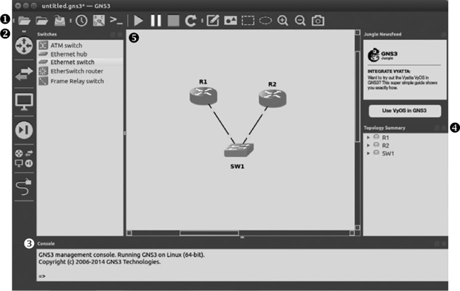
➊ GNS3 toolbar A series of icons to easily perform common tasks.
➋ Devices toolbar Used to add routers, switches, end devices, and security devices, as well as to create links between devices. To create topologies, select a device type from the toolbar and drag devices from the device window to your workspace. There are two types of devices: simulated and emulated. A simulated device mimics all the characteristics of an actual device (like an Ethernet switch node) and does not run an operating system. An emulated device emulates the hardware of an actual device and requires an operating system to function (like virtual Dynamips routers running Cisco IOS).
➌ Console A command line interface where you can manage aspects of your devices.
➍ Topology Summary Displays the state of devices in your project. A green circle by a device indicates that it has started, a red circle indicates that a device is stopped, and a yellow circle indicates that a device is suspended. Simulated devices (like the Ethernet switch node) are always green. To see the links in use on a given device, click the triangle next to the device name.
➎ Workspace The area in which you’ll design your network. Drag devices from the Devices toolbar to the workspace and link them together.
Now that you know what the main GNS3 screen looks like, let’s look more closely at the options you’ll find there.
The GNS3 toolbar contains several groups of icons that are roughly organized by function and offer a simple way to get things done. The first group deals with projects, the second with links, the third with devices and snapshots, and the fourth with additional ways to visually organize your projects.
The first group of toolbar icons, shown in Figure 4-2, deals with actions that affect entire projects.

From left to right, these icons are as follows:
New blank project. Creates a new project folder and allows you to choose what to name your project.
Open project. Opens a previously saved project. To open a project, choose the project folder name and select the file named <project_name>.gns3.
Save project. Saves a complete project to the GNS3 projects folder. By default, a PNG image file of your workspace is saved with your project.
The buttons in the second group of toolbar icons, shown in Figure 4-3, allow you to create project snapshots, show or hide interface labels, and connect to your devices using the virtual console port on your devices.
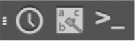
From left to right, these icons are as follows:
Snapshot. Creates a snapshot of your devices, links, and IOS configurations to record the state of your workspace at that time. You can save more than one snapshot and revert to a saved snapshot at any time. Options are Create, Delete, Restore, and Close.
Show interface labels. Shows or hides interface names used by a link. These labels are abbreviated and displayed with devices in your workspace (for example, f0/0 is displayed for FastEthernet0/0).
Console connect to all devices. Opens a console connection to all running routers in your workspace.
Note
When you open a console connection to all devices, your screen might become cluttered with open console windows unless your terminal supports tabbed sessions. When dealing with large topologies, you might find it easier to open and close single sessions as needed by right-clicking a device node and choosing Console.
The third group of toolbar icons, shown in Figure 4-4, primarily deals with controlling devices.

From left to right, these four icons are as follows:
Start/Resume all devices. Starts all stopped devices or resumes all suspended devices in your workspace.
Suspend all devices. Places all suspend-capable devices in a suspended state.
Stop all devices. Stops all devices.
Reload all devices. Reloads all devices. Be sure to save your router configurations and project before reloading or else you might lose your configurations!
The final group of toolbar icons, shown in Figure 4-5, provides tools to present your network layouts more clearly. You can add objects such as rectangles and ellipses to your project, and even generate a screenshot of your workspace.

From left to right, the icons in the last toolbar group are as follows:
Add a note. Creates text annotations in your workspace. Double-click text to modify it, and right-click the text object to change the Style attributes (such as font size and color). You can also rotate text objects from 0 to 360 degrees.
Insert a picture. Adds images and logos to your projects. GNS3 supports PNG, JPG, BMP, XPM, PPM, and TIFF file formats.
Draw a rectangle. Draws dynamically sizable rectangles. You can right-click a rectangle object to change the Style attributes for border and border color. Rectangle objects can be rotated from 0 to 360 degrees.
Draw an ellipse. Draws dynamically sizable ellipses. You can right-click an ellipse object to change the border style and color.
Zoom in. Zooms in your workspace to see details.
Zoom out. Zooms out of your workspace for a bigger bird’s-eye view.
Screenshot. Generates a screenshot of your workspace. The image can be saved as a PNG, JPG, BMP, XPM, PPM, or TIFF file and by default is saved in your GNS3/projects folder.
Objects (notes, pictures, and shapes) that you add to your workspace can be grouped into layers. To raise or lower an object, right-click the object and select Raise one layer or Lower one layer. This feature allows you to manipulate objects in a layer without affecting other layers. You can display layer positions for your objects by choosing View ▸ Show Layers from the menu, which is useful during advanced layer manipulation.
By adding shapes and colors with this toolbar, you can divide network components into logical groups. With text, you can add notes and reminders about how your project is configured. Figure 4-6 shows how you can present information more clearly using shapes, colors, and annotated text messages.
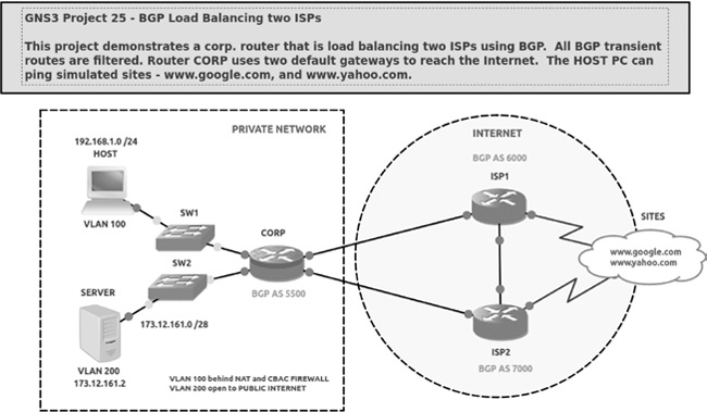
Once you’ve created several projects, it’s easy to forget how you configured them or what your objectives were. Adding notes (like the helpful one in Figure 4-6) is a simple way to quickly remind yourself of that information, especially after a few weeks or months have gone by. Notes are awesome—use them!
The Devices toolbar (shown in Figure 4-7) organizes devices by function. Click an icon on the Devices toolbar to see all the devices in that device group.

To add a device node to your project, click an icon from the Devices toolbar to display a list of configured devices and then drag a device to your workspace. You can press SHIFT to add multiple identical devices. From left to right, the device types in the toolbar are as follows:
Routers. Displays all available Dynamips router nodes that have been configured with a valid IOS image file, as well as IOU L3 routers.
Switches. Displays all available switch nodes, including Ethernet switch, Ethernet hub, ATM switch, Frame Relay switch, EtherSwitch router, and IOU L2 switches.
End Devices. Displays all available end devices, including QEMU guests, VirtualBox guests, host, and cloud.
Security Devices. Displays all available security devices, including ASA firewall, IDS/IPS, and any custom nodes you’ve created.
All Devices. Displays all available devices from the Devices toolbar.
Add a Link. When this is selected, your mouse pointer changes to a crosshair, indicating that you can link two devices together using their virtual interfaces. To link devices, click the first device and select an interface; then repeat for the second device to complete the connection.
Click the All Devices icon now, and you should see a window containing every configured device in GNS3. You can drag any of the devices to your workspace and use them in your project.
Now that you know your way around the GNS3 interface, let’s dig into some project management details. I’ll cover the easiest way to get things done, but keep in mind that GNS3 often provides more than one way to do things.
When you launch GNS3, a New project window appears, as shown in Figure 4-8. From here, you can either open an existing project or create a new one.
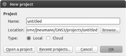
To create a new project, replace untitled with your project name, and click OK. If you’re already in GNS3, select File ▸ New to create a new project.
Once you’ve created a new GNS3 project, it’s time to build a topology, starting with some Dynamips routers.
Begin a project by dragging a couple of routers from the Devices toolbar to the GNS3 workspace. If you press SHIFT when adding devices, you should see a dialog that allows you to add multiple identical devices. Try adding the first pair of routers this way. If you don’t see any routers on the Devices toolbar, please refer to Setting Up Your First IOS Router to learn how to add devices to GNS3.
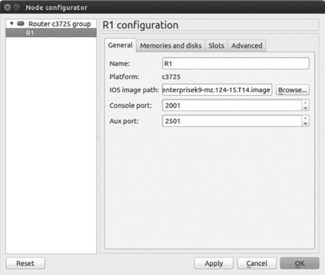
After adding the routers to your workspace, they should be named R1 and R2 automatically. The routers got their names from the command hostname %h found in the GNS3 file ios_base_startup-config.txt. This file contains default IOS settings that are applied to all your routers and are assigned to a device when it’s configured with an IOS image file. To locate the Dynamips configuration files, go to Preferences, choose Dynamips from the pane on the left, and choose IOS Routers. Select a configured router and click Edit to display the Dynamips IOS Router configuration options, shown in Figure 4-9.
From here, you can verify the path to your device’s startup-config and private-config files. When a router is placed in your workspace, the contents of the startup-config file ios_base_startup-config.txt are applied to the router startup configuration and loaded to the router’s running configuration when the router is started. If you would like to create custom parameters that are globally applied to your routers (for example, to bring up an interface automatically or use a preassigned username and password), use a text editor to modify and save the ios_base_startup-config.txt file. You can apply any valid Cisco IOS commands to the file, provided your IOS supports them, of course. You shouldn’t need to modify the ios_base_private-config.txt file. This file was installed by GNS3 so that you can use Secure Shell (SSH) between router restarts, without having to generate new crypto keys on your routers.

It’s important to note that the changes you make are applied only to routers you add to new projects and can’t be applied retroactively to routers in your previously saved projects.
After you’ve placed devices in your workspace, you’ll need to add links between them to create a fully functional network. This is equivalent to cabling up a real network, except that you’re using virtual cables rather than physical ones. To add links to your devices, click the Add a link icon in the Devices toolbar. Your cursor should change to a crosshair, indicating that you can select devices. To create a link, click a device. You’ll be presented with a drop-down menu of available interfaces, as shown in Figure 4-10.

A red circle next to an interface indicates that it’s available to use; a green circle indicates the interface is already being used by an existing link. Select any available interface to establish the link, and then select an interface on another device to complete the connection. You can create connections only between two compatible interface types. In other words, just like with physical hardware, you can’t plug a serial cable into an Ethernet interface.
At some point, you may want to break a link between two devices to simulate an outage, to reconfigure your network, or for some other reason. To break a link between two devices, right-click the link and select Delete, as shown in Figure 4-11.
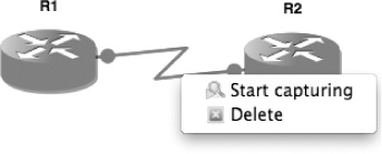
To reestablish a link, click the Add a link icon again and choose the same devices.
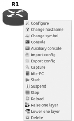
When you place virtual routers in your workspace, they have the same configuration options that were applied when you configured the device’s IOS image. But that doesn’t mean your routers are stuck with this configuration. Like PCs, Cisco routers have expansion ports to provide additional functionality, and GNS3 Dynamips routers provide the same expansion options as their physical counterparts. To modify a router’s hardware configuration, right-click the router and select Configure; then click the node name (R1, for example), as shown in Figure 4-12.
In the Node configurator dialog, you should see the available configuration options for that model of router. Basic models only allow you to add simple options, such as Cisco SLOT, WIC, or RAM cards, while more advanced models allow you to define features such as the chassis type or a Network Processing Engine (NPE) type that can be found in Cisco 7200 series routers.
You can configure and apply the same device options for memory and slots that were covered in Chapter 3, but the changes you make here will be applied only to the devices or device group you chose in your project. All other devices will remain unaffected.
I’ve shown you how to start and stop routers by right-clicking a router and choosing either Start or Stop, but you can also suspend your router by right-clicking it and choosing Suspend. Suspending a router is handy when you want to simulate a failure without having to go through the process of saving your configuration, stopping the router, and restarting it. In fact, repeatedly stopping and restarting GNS3 routers can cause Dynamips to crash with some IOS versions, so I recommend suspending and resuming instead.
The suspend feature really shines in network convergence tests. You can quickly simulate failures and recoveries to test routing protocols such as the Routing Information Protocol (RIP), EIGRP, and OSPF, as well as redundancy protocols such as the HSRP, Virtual Router Redundancy Protocol (VRRP), and Gateway Load Balancing Protocol (GLBP). To simulate a failure, click Suspend and monitor your other routers to verify that failover or convergence has occurred.
To simulate a recovery, resume the router by right-clicking the device and choosing Start. Due to throughput limitations placed on Dynamips because of the emulation, failover or convergence may take a little longer than you’re used to when using real hardware. Don’t worry—this is totally normal.
Of course, even if you can start and stop your routers, you won’t be able to do too much with them until you’ve logged on to a console.
You log on to your routers using the simulated console port. If this sounds familiar, it’s because that’s also how you log on to actual Cisco equipment. On a physical piece of hardware, the console port is where you plug in Cisco’s little blue serial console cable. Be sure the router is started before you open a console connection; otherwise, you won’t get a console screen.
Configuring Terminal Settings
Whether you’re running Windows, OS X, or Linux, there are a number of terminal types available to use with GNS3. But why would you prefer one over the other? One reason might be that it’s what you have installed on your system. On Linux, for example, you may be using the Gnome Desktop, which has gnome-terminal installed by default. If that’s the case, you may want to modify the GNS3 terminal setting to use gnome-terminal. Another reason is that some terminal programs provide more features than others. You may want to choose a terminal type that allows you to use tabbed windows, for example, so you can open more than one console at a time without a bunch of open windows cluttering the screen.
To modify the terminal settings, go to Preferences, click General, and then click the Console applications tab to display the window shown in Figure 4-13.

From here, you can choose a predefined terminal type and customize the command settings under Console application command. (Check your terminal application documentation to find out what options are available on your system.) When you’re done, click Set and then Apply and OK.
To log on to all your routers at once, click the Console connect to all devices icon in the second toolbar group (see Figure 4-3). To log on to a single router, right-click the router node in your workspace and select Console or Auxiliary console from the menu (see Figure 4-14).
To change the Transmission Control Protocol (TCP) port number on which a router’s console or AUX port listens, right-click a device in your workspace, click Configure, and select the General tab. The port number you choose must be unique for every device in GNS3 and on your PC. As a rule, I try not to mess with port numbers unless I must. GNS3 does a pretty good job of keeping them all straight, and mucking with them can lead to headaches. But if some other TCP/IP application running on your PC happens to conflict with GNS3, you may have to make some changes before you can log on to your router.
Once you’ve established a console connection to the router, you should see a familiar Cisco console window.
Trying 127.0.0.1...
Connected to 127.0.0.1.
Escape character is '^]'.
Connected to Dynamips VM "R1" (ID 1, type c3725) - Console port
Press ENTER to get the prompt.
ROMMON emulation microcode.

Cisco 1720 (MPC860) processor (revision 0x202) with 55206K/9830K bytes of memory.
Processor board ID FTX0945WOMY (4279256517), with hardware revision 000
M860 processor: part number 0, mask 0
Bridging software.
X.25 software, Version 3.0.0.
1 FastEthernet/IEEE 802.3 interface(s)
32K bytes of non-volatile configuration memory.
4096K bytes of processor board System flash (Read/Write)

SETUP: new interface FastEthernet0 placed in "shutdown" state

Press RETURN to get started!
00:00:02: %LINK-5-CHANGED: Interface FastEthernet0, changed state to administratively down
00:00:03: %LINEPROTO-5-UPDOWN: Line protocol on Interface FastEthernet0, changed state to down
R1#
At this point, you can begin using standard IOS commands to configure the router. One command that might look odd is the show flash command. Normally this command displays files saved in flash memory, such as the router’s IOS image file and other default files from Cisco. In GNS3, however, you’ll notice there are no files saved here by default. What’s more, the flash drive may be unformatted; if that’s the case, you’ll need to issue the erase flash: command before you can save files to flash memory. Otherwise, you may receive an error similar to the following:
%Error opening slot0:router-confg (Bad device info block)
Note
If you use an NM-16ESW switch module, you may have to erase your router’s flash memory before you create VLANs; otherwise, the VLAN database (vlan.dat) will not be able to be saved.
This section has been all about Dynamips routers so far, but you can also use switches in your GNS3 projects, which I’ll cover next.
The Ethernet switch node is an emulated virtual switch that allows you to create VLAN access and trunk ports. The Ethernet switch node supports access ports, industry-standard 802.1Q trunk ports, and QinQ tagging. It does not, however, support Cisco’s proprietary Inter-Switch Link (ISL) trunking protocol.
To use an Ethernet switch node, drag the node to your workspace. You never have to start an Ethernet switch node; they’re always ready to use.
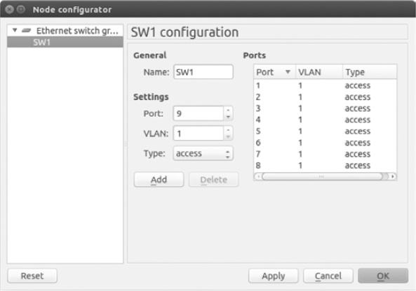
To configure the switch, right-click the Ethernet switch node icon and select Configure. Using the Node configurator window shown in Figure 4-15, click the switch name (SW1, for example) to modify the default switch ports or add new ports.
By default, there are eight access ports assigned to VLAN 1. To change a port, click the port number and modify the settings as needed. When you’re done, click Apply and OK. To add a new port, define the port settings and click the Add button; then click Apply. When you’re finished adding ports, click OK to complete the setup.
One alternative to the Ethernet switch node is to configure a Dynamips router with a network switch module. The advantage of using a switch module is that it supports more features (such as the Spanning Tree Protocol); the downside is that using a network switch module uses more PC resources. If you need the functions of only a simple switch, I recommend you stick with the Ethernet switch node. If you need full IOS switching capability, use a router with a switch module installed like the EtherSwitch router, or use an IOU L2 switch image (discussed in Chapter 9).
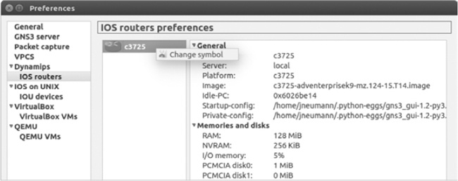
You can change the symbols that are used to represent devices in your workspace and choose where your devices are located in the Devices toolbar. Let’s say you want to change an IOS router’s symbol. To change the symbol of the device, select Edit ▸ Preferences on Linux and Windows or select GNS3 ▸ Preferences on OS X. Next, go under the device you want to change, right-click the device icon, and select Change symbol, as shown in Figure 4-16.
You can change the symbol for IOU devices, VirtualBox virtual machines, and QEMU virtual machines in the same way. The Symbol selection window, as shown in Figure 4-17, should appear after you click Change symbol.
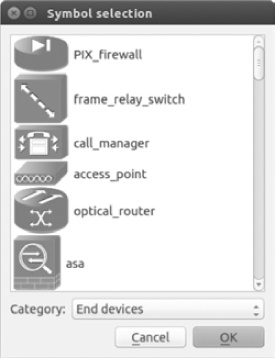
To change a device symbol, scroll down in the Symbol selection window and select the symbol you want to use. Next, use the drop-down menu to choose a category. This is the category where the device will be placed in the Devices toolbar. The categories include Switches, Routers, End Devices, and Security Devices. When you’re finished, click OK to complete the change.
In this chapter, you learned the basics of setting up a GNS3 network, so now is a good time to create a few labs and practice what you’ve learned. If you’re studying for a Cisco certification, spending as much hands-on time as possible with Cisco gear is the only way to gain enough experience to pass the exams. (They’re tough!)
Start by creating the network in Figure 4-1. After creating the topology, log on to the routers, configure their interfaces, and try pinging between them. Simulate a failure and recovery by using the suspend and resume feature or by starting and stopping a device. Once you’ve explored some IOS commands and GNS3 features, try creating a simple CCNA lab with three or more routers; there are plenty of CCNA and CCNP example labs online.
One last word of caution: if you create large topologies that use multi-protocol routing, you might find that you have to increase your router’s protocol timers to prevent your interfaces from repeatedly going up and down. (It’s rare, but it does happen sometimes.) The problem is caused by the inherent effects of latency within Dynamips. Serial connections are another common problem area; some router images can be flaky when running on emulated serial ports. If you find a router’s serial port is acting up by either crashing your router or flapping the connection, try another router model or different IOS image. In general, c36xx, c37xx, and 7200 IOS images are the most stable with Dynamips and should be used whenever possible.
In Chapter 5, you’ll explore the basics of capturing network packets with Wireshark and expanding your networks by adding hosts using VPCS, VirtualBox, and Linux.