
Now that you’ve seen GNS3’s most commonly used features, let’s explore some fun tricks you can do with your GNS3 projects. First, you’ll create a simulated Cisco access server that functions like its real Cisco counterpart.
Next, I’ll show you how to move your GNS3 projects from one operating system to another and how to copy your GNS3 virtual router configurations from GNS3 to real Cisco routers. Finally, you’ll look at sharing a project’s resource load using multiple PCs, create some nerdy labs, and simulate a few real network scenarios.
An access server allows you to manage all network devices from a central console so you can concurrently log on to multiple device consoles and easily switch between them. It’s an efficient way to manage devices on large Cisco networks, and with only a little effort you can create a fully functional virtual Cisco access server (sometimes called a terminal or comm server) to manage your GNS3 devices. I find that using a virtual access server is a fast way to manage and configure devices in GNS3, and you can also do it to learn the commands and keystrokes of a real access server.
A GNS3 virtual access server has two components. The first is a Cloud node configured with a virtual interface; you’ll use a Loopback Adapter driver in Windows and a TAP adapter in Linux. The second is a Cisco Dynamips router that acts as the management console. Configuring the virtual access server itself varies slightly depending on your operating system. I’ll cover Windows and Ubuntu Linux, but the concepts apply to other Linux operating systems. Unfortunately, OS X is not supported at the time of writing.
Whether you use Windows or Linux, you’ll need to install a virtual network adapter and assign it an IP address. On Windows, you’ll install a Loopback Adapter driver, and on Unix-based systems like Linux, you’ll install a TAP driver. If you’re a Linux user, you can skip to Configuring a TAP Adapter in Linux.
If you haven’t done so already, install the Microsoft Loopback Adapter driver. (Refer to Using a Loopback Adapter on Windows.) After you’ve installed the adapter, assign it an IP address. The IP address and subnet mask you choose must be unique from any network adapters already configured on your PC and from any IP addresses that you plan to use in your GNS3 network topology.
To configure the adapter, open the Windows Control Panel and select Network and Sharing Center. Next, select Change Adapter Settings to display a list of available adapters, as shown in Figure 10-1.
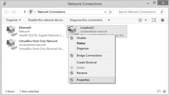
Right-click the Microsoft Loopback Adapter driver and select Properties. From the Properties window, select Internet Protocol Version 4 (TCP/IPv4) and then click the Properties button to display the IP address settings, shown in Figure 10-2.

Select Use the following IP address and enter a unique IP address and subnet mask. I’ve chosen 9.9.9.9 and 255.255.255.0, but any address and mask will work, as long as they’re unique from any addresses assigned to any Ethernet adapters in your PC, and from any addresses that you plan to use in your GNS3 network topology. There’s no need to include a default gateway address or provide any DNS servers because they won’t be used by the access server. When you’re finished, click OK to complete the configuration. Now close any open windows and launch GNS3. If you’re a Linux user, read on; otherwise, you can skip to Preparing the GNS3 Server.
On Ubuntu Linux, you’ll use a virtual TAP adapter for the access server. Open a terminal and enter the following command to install the drivers:
$ sudo apt-get install uml-utilitiesTo enable tap0, enter the following command, replacing jneumann with your Linux username:
$ sudo tunctl -u jneumann -t tap0Next, assign a unique IP address to the tap0 interface. The IP address and subnet mask you choose must be unique from any network adapters configured on your PC and from any IP addresses that you plan to use in your GNS3 network topology.
$ sudo ifconfig tap0 9.9.9.9 netmask 255.255.255.0 upTo ensure the tap0 interface maintains its IP address and is available after a reboot, you’ll need to change your Linux network settings.
Open the interfaces file under /etc/networks/ in a text editor like pico or vi. You’ll need administrator privileges to make changes to the file, so log in as root or run the editor with the sudo command, as in sudo pico interfaces. Then, append the following to the end of the file:
auto tap0
iface tap0 inet static
        pre-up tunctl -t tap0
        up ifconfig tap0 up
        down ifconfig tap0 down
        address 9.9.9.9
        netmask 255.255.255.0
With these commands in place, save the interfaces file, close it, and reboot. When Ubuntu restarts, the TAP driver should automatically load, and interface tap0 should be ready to use.
Warning
Use caution when editing the /etc/networks/interfaces file. Entering a typo here can prevent Ubuntu from booting properly.
Enter the ifconfig command to verify the tap0 settings:
  $ ifconfig
  --snip--
➊ tap0    Link encap:Ethernet HWaddr 16:81:25:c1:cc:8c
➋         inet addr:9.9.9.9 Bcast:9.9.9.9.255 Mask:255.255.255.0
           UP BROADCAST MULTICAST MTU:1500 Metric:1
           RX packets:0 errors:0 dropped:0 overruns:0 frame:0
           TX packets:0 errors:0 dropped:0 overruns:0 carrier:0
           collisions:0 txqueuelen:500
           RX bytes:0 (0.0 B) TX bytes:0 (0.0 B)
The output from ifconfig should show that the tap0 adapter is enabled ➊ and configured with an IP address ➋. After you’ve installed and configured a virtual adapter, you’ll need to set up the GNS3 server.
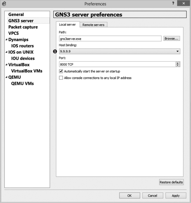
On Windows, run GNS3 as administrator. Begin by binding the GNS3 server to the IP address of your virtual interface; otherwise, your access server will not work. Click Edit ▸ Preferences and choose GNS3 server from the left column. Select the Host binding drop-down menu and then select the IP address you assigned to the virtual interface, as shown in Figure 10-3.
In Figure 10-3, the IP address is 9.9.9.9 ➊. Click Apply and OK, and the GNS3 server should restart with the new host binding.
With your GNS3 server bound to the virtual adapter’s IP address, you can create the virtual access server. The access server is created using two devices: a Cloud node and a Dynamips IOS router.
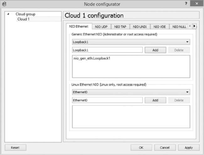
Begin a project by adding a Cloud node to your workspace. Right-click the Cloud node and select Configure. If you’re running Windows, select the NIO Ethernet tab (shown in Figure 10-4).
Click the drop-down menu under Generic Ethernet NIO and select your Microsoft Loopback Adapter driver (Loopback1 in this example); then click Add, Apply, and OK to complete the configuration.
If you’re running GNS3 on Ubuntu Linux, configure the Cloud node using tap0. Instead of NIO Ethernet, select the NIO TAP tab and enter tap0 in the TAP interface field, as in Figure 10-5.
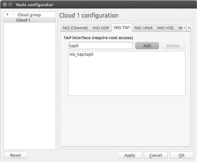
When you’re finished, click Add, Apply, and OK to complete the Cloud node configuration.
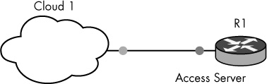
After configuring the Cloud node, add a Dynamips router to your workspace and create a link from the router to the Cloud node. Together, these two devices comprise the virtual access server, shown in Figure 10-6. They will not be linked to any other devices in your GNS3 project.
After linking the virtual access server components together, add more routers to your workspace to create a simple three-router network, as shown in Figure 10-7. This is the network topology that will be managed using the virtual access server.
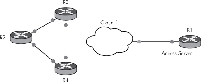
Figure 10-7 shows that you have created a virtual access server using router R1 and a Cloud node (Cloud 1), and you have created a network topology that’s made up of three routers, named R2, R3, and R4.
Now that you’ve created both the access server and a GNS3 network topology, you can configure the access server router. Assign router R1 an IP address from the same network as your PC’s virtual adapter, and test connectivity from R1 to the virtual adapter interface. For example, if you assigned the virtual adapter the IP address 9.9.9.9 255.255.255.0 as I have, you could assign the access server router R1 any IP address in that network range. I use the IP address 9.9.9.8 and the subnet mask 255.255.255.0.
To configure the address on interface f0/0, open a console connection to router R1 and enter the following commands:
R1>enable
R1#configure terminal
R1(config)#interface f0/0
R1(config-if)#ip address 9.9.9.8 255.255.255.0
R1(config-if)#no shutdown
R1(config-if)#exit
R1(config)#exit
R1#ping 9.9.9.9
Type escape sequence to abort.
Sending 5, 100-byte ICMP Echos to 9.9.9.9, timeout is 2 seconds:
!!!!!
Success rate is 100 percent (5/5), round-trip min/avg/max = 1/1/4 ms
In this configuration, router R1’s interface f0/0 is linked to the Cloud node and configured with IP address 9.9.9.8 255.255.255.0. Test the connection between R1 and the virtual interface using a ping command. If the ping test is successful, you’re ready to move on. If the ping test is unsuccessful, verify that all your interfaces are enabled and that the virtual interface (loopback or TAP) is configured with the proper IP address and subnet mask.
After configuring an IP address on the virtual access server (R1), you’re ready to configure an IP hostname table using information gathered from the devices that the access server will manage. In this project, the devices are routers R2, R3, and R4. Using Cisco IOS commands, you’ll create an IP hostname table using the IP address of the virtual interface (9.9.9.9) and the console port numbers that GNS3 has assigned to the routers used in your network topology. A Cisco IP hostname table works much like a Unix hosts file, except that you’ll also include port numbers in the table. You’ll create an entry for each device in the topology that you want to manage.
Begin by finding the console port numbers for routers that the access server will manage. In this project, you’re interested only in the console port numbers for routers R2, R3, and R4. You can quickly find any device’s console port number by hovering your mouse over the device, as shown in Figure 10-8.

Router R2’s console is on port 2002. Because console port numbers are assigned sequentially as devices are added to a project, routers R2, R3, and R4 should have been assigned the console port numbers 2002, 2003, and 2004, respectively. If you’re unsure, hover your mouse over each device icon to verify the information.
Note
If you add multiple routers at the same time, instead of one at a time, the console port numbers may not be assigned in sequential order.
To create the IP hostname table, open a console on router R1 (the access server) and enter the following commands:
R1#configure terminal
R1(config)#ip host R2 2002 9.9.9.9
R1(config)#ip host R3 2003 9.9.9.9
R1(config)#ip host R4 2004 9.9.9.9
R1(config)#exit
R1#
Notice the host port numbers correspond with the unique console port numbers from the three routers you want to manage, but the IP address is always the same; it is the IP address assigned to the virtual adapter (9.9.9.9). That’s because when the virtual access server opens a console to one of the lab routers, GNS3 creates a telnet session from the access server to the routers using the virtual adapter’s IP address. From there, it connects to the individual console port number that you assigned. For example, when the access server opens a console connection to router R2, GNS3 telnets to IP address 9.9.9.9 using port number 2002. This is similar to how an actual Cisco access server works.
Now, verify which hosts are configured on your virtual access server with the show hosts command.
R1>show hosts
Default domain is not set
Name/address lookup uses static mappings

Codes: UN - unknown, EX - expired, OK - OK, ?? - revalidate
       temp - temporary, perm - permanent
       NA - Not Applicable None - Not defined

Host➊                      Port➋ Flags      Age Type  Address(es)➌
R2                         2002  (perm, OK)  0   IP    9.9.9.9
R3                         2003  (perm, OK)  0   IP    9.9.9.9
R4                         2004  (perm, OK)  1   IP    9.9.9.9
This command displays the hostname ➊, port number ➋, and IP address ➌ for each host configured on the access server.
To learn more about configuring and using a real Cisco access server, visit the Cisco website (http://www.cisco.com/) and search for configuring a comm server. For now, you should know all you need to try your virtual access server.
After you’ve fully configured the access server and started your project routers, you should be able to manage those routers using the access server. You can open a console connection to several routers, and easily switch between them.
Begin by opening a console connection to R1. Right-click router R1 and choose Console. Next, type the name of a host you want to manage and press
R1>R2
Translating "R2"
Trying R2 (9.9.9.9➊, 2002➋)... Open
Connected to Dynamips VM "R2" (ID 1, type c3600) - Console port
Press ENTER to get the prompt.

R2>➌
In this example, I open a session with router R2 by entering R2 from the access server command line. The output shows that a session is established using IP address 9.9.9.9 ➊ and port number 2002 ➋, and the prompt ➌ has changed to the router being managed (R2 in this example). After the session is open, you can configure the router as though you opened a console directly from GNS3.
When you’re finished configuring the router, return to the access server console; just press SHIFT-CTRL-6 and then press the X key. (Cisco calls this combination of actions an escape sequence.) After returning to the access server console, enter the name of another router in your project to open a console on it. Try entering R3 now, and configure the router however you’d like. When you’re done, use the escape sequence again to return to the access server.
Even though you’re currently logged on to the access server console, the sessions on the other two routers remain open. To display a list of open sessions and their corresponding connection numbers, enter the show sessions command.
R1>show sessions
Conn Host                     Address          Byte  Idle  Conn Name
     1 R2                      9.9.9.9           0     0    R2
 ➊*  2 R3                     9.9.9.9           0     0    R3
You should see two active connections (1 and 2). The asterisk ➊ next to Conn 2 indicates that router R3 was the last session used. To return to the last session, press ENTER. To return to a different session, type a connection number and press ENTER; for example, you’d enter 1 to return to router R2.
When you’re ready to disconnect from an open connection, enter the disconnect command followed by the connection number; then press ENTER to confirm closing the session.
R1>disconnect 2
Closing connection to R3 [confirm]
R1>
In this example, I’ve disconnected from router R3 (connection 2). After disconnecting a session, you will have to enter the hostname again to reconnect to the device.
You may want to adjust the timeout setting (via the console exec-timeout parameter) on your routers and access server to ensure that you’re not logged out automatically during idle times, such as when you’re not actively configuring a router. The default value is ten minutes, but it can be set higher, lower, or changed to infinite.
The following commands set the console timeout to zero minutes and zero seconds (infinite):
R1>enable
R1#configure terminal
R1(config)#line console 0
R1(config-line)#exec-timeout 0 0
GNS3’s default startup-config should have already done this for you, but know that from a security standpoint, never allowing the router to time out is a bad idea in production environments. It is, however, highly convenient in lab environments such as GNS3.
One of the benefits of GNS3 is that it allows you to create and test network configurations that can later be used on real equipment. You simply export a router configuration in GNS3 and load it on a real Cisco IOS router.
After thoroughly testing a router configuration inside GNS3, you’re ready to export it and load it on a real Cisco router. You can export all the routers in your project, or you can export the configuration of an individual device. Before exporting a GNS3 IOS router configuration, log in to that router and save its running-config file to the startup-config file. The saved startup-config is the configuration that will be exported by GNS3.
R1#copy running-config startup-configIf you have any IOU devices in your project, you’ll need to make copies of their running-config files, too. Just log in to the device and enter the following command to create a text file of the IOU configuration:
IOU#copy running-config unix:initial-config.cfgAfter you’ve saved a running-config file, you can export all device configurations at the same time by selecting File ▸ Import/Export device configs. GNS3 should then show the dialog in Figure 10-9.
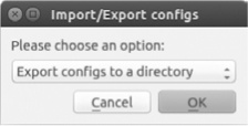
Select Export configs to a directory from the drop-down menu, click OK, browse to the location where you want to save your configuration files, and click Open to save the configurations. The exported configuration files will be named after the devices in your workspace, like R1_startup-config.cfg and IOU1_initial-config.cfg. For each IOS device, you’ll also see a private config file that’s used only by GNS3 and contains SSH crypto keys. You don’t need to upload this to your real Cisco router. This export method is an all-or-nothing procedure that exports all the device configurations in your project. To export the configuration of a single device, save the configuration, right-click the device in your project, and select Export config. The saved file will be named using the device name.
Now, let’s look at how to import a live Cisco router configuration into GNS3. Begin by logging on to your real Cisco router and saving its configuration to your PC, using FTP or TFTP. Use a text editor to clean up any interface name discrepancies. Next, append the name of the exported file with .cfg to ensure that GNS3 can recognize the file. If you haven’t done so already, save your GNS3 project and stop the GNS3 router that is the target for the import. Finally, right-click the GNS3 router and choose Import config. Browse to the directory where you saved the .cfg file, and select the file to import it into the router. When you restart your GNS3 router, it should load and run the IOS configuration that you copied from the live Cisco router.
Note
When moving configurations back and forth between real routers and GNS3, you may have to perform some IOS configuration cleanup. For example, your GNS3 router may have an interface named FastEthernet 0/0 while your real Cisco router has an interface named FastEthernet 0 instead. In this case, use a text editor and modify the file before importing it into GNS3.
Someday you may want to have your projects run on a PC that uses a different operating system than your existing PC. If your GNS3 projects include only Dynamips IOS routers and switches, you can copy them between different platforms such as Windows and Linux with minimal effort. But if they’re made up of other device types such as IOU, QEMU, or VirtualBox, the process can get complicated. Either way, moving a project between platforms is mostly a matter of copying one or more projects from your old GNS3 projects folder to the projects folder on a new PC.
If your project consists of only Dynamips routers, then almost no additional configuration is necessary, as long as the target computer has compatible image files. If the target PC is configured with different IOS image files or the images are stored in a different directory, GNS3 should prompt you to substitute the original image file with one that’s already configured on the target computer, as shown in Figure 10-10.
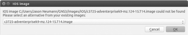
In this example, you’re moving a project from a Windows PC to a Linux host. Even though the c3725-adventerprisek9-mz-124-15.T14.image file is configured on the Linux host in Figure 10-10, GNS3 was unable to locate it because Windows stores IOS image files using a different path than Linux.
In this case, GNS3 should display a list of configured IOS images and allow you to choose one. Use the drop-down menu to select an image and click OK. After selecting the image, GNS3 should update the path information in the project file on the target PC. To make the change permanent, you have to save your project. All of the original IOS configurations should remain intact, and your project should run as expected. If it doesn’t, start again and try using a different image file.
Copying projects that contain IOU devices can be a bit more involved. The easiest method is to re-create the IOU devices in the project on the target PC and then upload the original IOU configuration. Before copying the project to a new platform, follow these steps:
Log on to each IOU device in the project and copy the running configuration to the unix:initial-config.cfg file. Right-click an IOU device and choose Export config to save the configuration. Be sure to copy the exported configuration file to the new system when you copy your project.
Open the project on the target PC and resolve any IOS image file substitution issues (refer to Figure 10-10).
On the target PC, delete the IOU device from your project, add a new one, and link the IOU device to other project devices using the same interfaces as the original project.
To import the configuration, follow these steps:
Right-click the IOU device on the target PC and click Import config.
Browse to the directory where the IOU configuration is saved and select the file. Do this for each IOU device in your project.
When you’re finished, start all the devices in your new project and verify that everything works as expected. Log on to each IOU device and examine its configuration. If everything looks good, save your updated project.
Finally, let’s look at transferring projects that use VirtualBox.
If you’re using a VirtualBox device in your original project, you’ll have to export it to an OVA file. Launch VirtualBox and choose File ▸ Export Appliance to save the device file. With the OVA prepared, follow these steps:
Copy the OVA file to the new PC, launch VirtualBox, and choose File ▸ Import Appliance to import the file.
Launch GNS3 and add the VirtualBox virtual machine under Preferences, as discussed in Importing Appliances.
Add the device to your GNS3 project and link it to other devices, selecting the same interfaces that were used in the original project.
When you start your project on the new PC, your VirtualBox devices should have the same configuration they had on the old PC.
The GNS3 management console provides a command line interface that you can use to control project devices. Based on the original Dynagen console that was written for Dynamips, the management console has been adapted and updated for GNS3. I won’t cover every aspect of the console here, but I will show you some more useful things you can do with it.
By default, the management console should be visible when you launch GNS3. If not, select View ▸ Docks ▸ Console to display the console window.
From the management prompt (=>), enter help or a question mark (?) to see a list of commands. As you can see from the following listing, you can perform familiar tasks from the CLI, such as starting and stopping devices:
=> ?

Documented commands (type help <topic>):
========================================
console  debug  help  reload  show  start  stop  suspend  version
To display the details and syntax of a specific command, enter help followed by a command name, as shown here:
=> help show
   Show detail information about every device in current lab:
    show device

    Show detail information about a device:
    show device <device_name>

    Show the whole topology:
    show run

    Show topology info of a device:
    show run <device_name>
The show command offers a lot of different options to display information about your hypervisors, devices, and configurations. For example, the show run command displays the entire contents of your project configuration file.
Two commands that are useful for testing networks are suspend and start. Together they can be used to simulate a router failure and recovery. Another helpful command is the debug command. It can provide useful information when a project isn’t running properly.
You can run devices using multiple PCs, allowing you to distribute the resource load across multiple computers. Sharing resources lets you use one PC to design your projects while running the devices themselves on one or more other PCs. This means you can create and manage your GNS3 project using a low-end workstation (such as an old laptop) while actually running the devices on a high-end server. If you use multiple servers, you could build a GNS3 uberlab!
In this section, I’ll show you how to share resources in a basic client/server setup and cover strategies for creating an uberlab. Disable the firewalls on all PCs before you begin configuring client/server (or multiserver) load sharing, and let’s get started.
In this scenario, you operate GNS3 on one computer, while another GNS3 server runs on another PC. If you’re running GNS3 on OS X or Windows, this may sound familiar because that’s how the IOU virtual machine works. The IOU virtual machine runs on a virtual computer rather than on a separate PC, but otherwise, the concept is the same.
In this example, I will use Windows for the client PC and Ubuntu Linux for the server PC. Begin by installing GNS3 on the two workstations. One workstation will be the client, where you configure and manage your projects, and the other is the server. The server will run only Dynamips routers, and it should have the better hardware because it will do most of the work. The more processing power and memory the server has, the better your devices will perform.
Launch GNS3 on each computer and configure an IOS image file. This lets you run both local and remote Dynamips routers at the same time and network them together using GNS3 from the client PC. When configuring GNS3 on the server PC, be sure to record the path and filename of your IOS image file. On my Ubuntu server, my image file path is /home/jneumann/GNS3/images/IOS/c3725-adventerprisek9-mz.124-15.T14.image. You need this information to configure the remote Dynamips router on the client PC.
Next, find the IP address of each of your GNS3 PCs. In this example, my client PC is configured with the IP address 172.16.231.202, and my server PC is configured with the IP address 172.16.231.205. After configuring GNS3 and recording the IP and image path information, you should be ready to begin.
You must run the gns3server program from its install directory. Log on to the remote server PC and open a terminal window on Linux and OS X or a command prompt if you’re running Windows. On Windows, go to the C:Program FilesGNS3 directory, and on OS X go to the /Applications/GNS3.app/Contents/Resources/Server/Contents/MacOS directory.
When starting the server program, you have to specify the IP address of your server PC and the port number that the server will listen on; enter the command gns3server --host server-ip --port port-number. If you don’t know the IP address of your server PC, you can be lazy and use 0.0.0.0 and gns3server will listen on all configured interfaces. In the following example, I’ve started the gns3server program on Ubuntu Linux from the /usr/local/bin/ directory.
$ gns3server –-host 172.16.231.205 -–port 8000
2015-06-06 18:32:45 INFO main.py:145 GNS3 server version x.x
2015-06-06 18:32:45 INFO main.py:147 Copyright (c) 2007-2015 GNS3 Technologies
Inc.
2015-06-06 18:32:45 INFO main.py:150 Config file /home/jneumann/.config/GNS3/
gns3_server.conf loaded
2015-06-06 18:32:45 INFO main.py:163 Running with Python 3.4.2 and has PID 3436
2015-06-06 18:32:45 INFO main.py:72 Current locale is en_US.UTF-8
2015-06-06 18:32:45 WARNING project.py:397 Purge old temporary project f3b11fb8
-82ed-42c1-b66a-226198ce6189
2015-06-06 18:32:45 INFO server.py:214 ➊ Starting server on 172.16.231.205:8000
After starting the server, you should see similar output, and if all goes well, the server will start on 172.16.231.205:8000 ➊, shown on the last line of the output. This indicates the server program is listening on IP address 172.16.231.205 using port number 8000.
That’s all there is to configuring the server, so you can turn your attention to the GNS3 client, a Windows PC in this example. In GNS3, select Edit ▸ Preferences and select GNS3 Server, as shown in Figure 10-11.
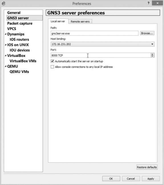
Click the Host binding drop-down menu and select the IP address of your Ethernet interface. On this PC, the address is 172.16.231.202. Click Apply to complete the configuration.
Next, add the remote GNS3 server’s IP address to the remote server list on the client. Click the Remote Servers tab, as shown in Figure 10-12.
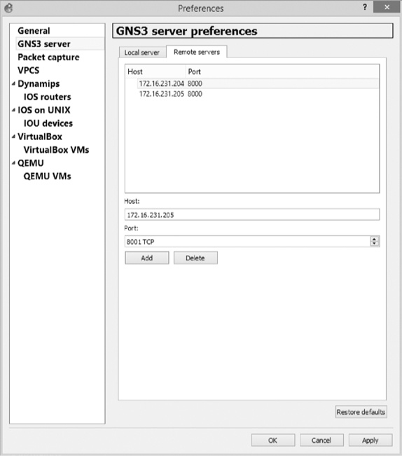
In the Host field, enter the IP address of the remote GNS3 server. In this example, that IP address is 172.16.231.205. The default port number should be 8000, but you can change it if you’ve chosen some other port number on the remote PC. After adding the remote server, click Apply to save the settings.
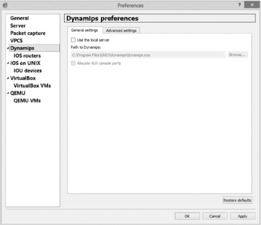
Next, select Dynamips from the side menu and click the General settings tab, as shown in Figure 10-13.
Uncheck the Use the local server setting and click Apply. This ensures that you have the option to select a remote server when you configure a Dynamips router. Next, click IOS routers, as shown in Figure 10-14.

Click New to add a remote IOS router to your client PC, as shown in Figure 10-15.
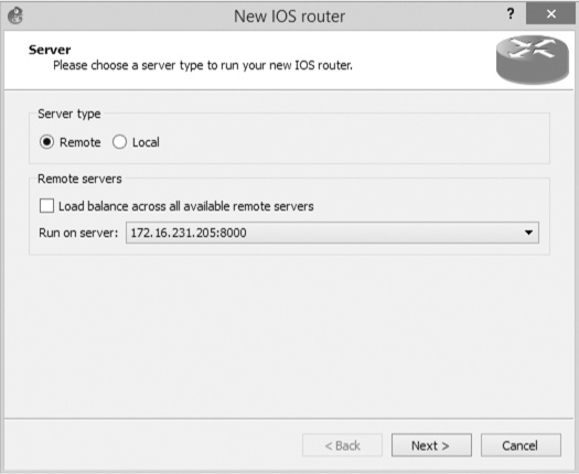
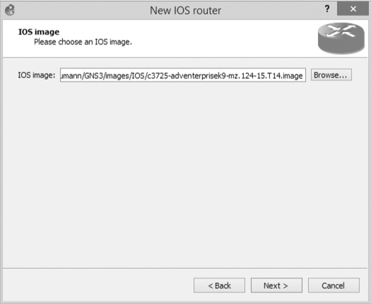
Under Server type, select Remote and uncheck Load balance across all available remote servers. Click the Run on Server drop-down menu, select your remote server’s IP address from the list, and click Next to continue. Enter the path and IOS image name that you recorded from the remote server, as shown in Figure 10-16.
After entering the path and filename, click Next to continue. Enter a name in the Name field for your router, as shown in Figure 10-17.
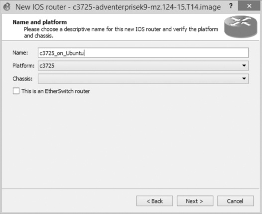
I’ve named my router c3725_on_Ubuntu so that I can easily identify the router in the Devices toolbar, and I know from the name that it’s configured to run on a remote server.
At this point, you can click through the remaining options as if you’re configuring a local Dynamips router. Be sure to enter an Idle-PC value when asked, or calculate one if you haven’t already done so. Remember, Idle-PC values are calculated on a per-image basis, so the same value can be used on any PC that’s using the same IOS image file.
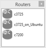
When you’re finished adding the router, it should be displayed in the Routers section of the Devices toolbar, as shown in Figure 10-18.
This example has two c3725 routers; one is a local router installed on the Windows PC, and the other is installed on the remote Ubuntu server. When you create a project, you can use both routers in the same project, reducing the CPU and memory consumption on the client PC by half.
Now that you know how to set up GNS3 using multiple PCs, you can leverage the ability to create large GNS3 projects.
Running QEMU on a Remote Server
In addition to running IOU and IOS routers on a remote server, you can also run QEMU on a remote server. Just be sure to install QEMU on the server PC before you begin. The process of setting up a remote QEMU device on the client PC is almost the same as any other remote device. However, during the New QEMU VM wizard, you will need to select the QEMU binary file for the virtual machine, shown in Figure 10-19.
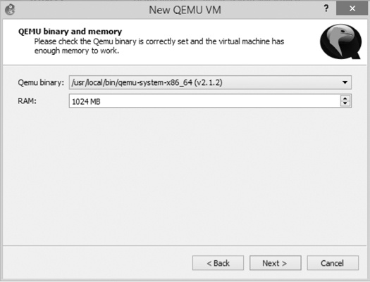
GNS3 should query the remote server for a list of installed QEMU binary files, and the virtual machine that you create should run on the remote server using the binary file that you select. Use the drop-down menu to select a binary file for your virtual machine, usually qemu-system-i386 or qemu-system-x86_64. Adjust the RAM size and click Next . Configure the remaining options as if the virtual machine were a local device.
GNS3 is all about scalability, and you can use it to create really large projects with dozens of switches and routers. One of the best ways to create an uberlab is to use multiple GNS3 servers. But what if you have one really fast computer and a few others that don’t perform as well? In that case, you may want to run more devices on one machine than the other. For example, you might run most of your routers on the high-end server and run fewer devices on the less powerful machines.
An uberlab doesn’t need to be confined to computers running on your local area network. If you’re using GNS3 on a corporate network with multiple sites connected by a VPN, you can use the client/server model to run a variety of hypervisors from across town or even across the country! All you have to do is start the gns3server application on a remote computer (over the VPN) and configure your local client using the IP address of the remote PC. The only difference between this and a regular client/server setup is that packets will be sent through the VPN to the remote server.
You’ve explored the tools you need to configure all sorts of projects in GNS3, but what should you do with this newfound knowledge? You could study for certifications or just have some fun! In this section, I discuss both. Many of these projects are intended for advanced users, but feel free to modify them to create projects and challenges that are better suited for your skill level.
GNS3 is an amazing tool for education and certification, and it has everything you need to get Juniper or Cisco certified, starting at the entry-level JNCIA or CCNA all the way up to the crown jewel of Cisco certifications, the CCIE.
For entry-level exams such as CCNA or CCNP, start by searching online to find all sorts of network examples. You may even want to use the CBT Nuggets or Bryant Advantage videos with GNS3. Their videos are a good way to get started, and GNS3 is a great tool for experimenting with the concepts they introduce. If you’re studying for CCIE, you may want to use something like the INE workbooks (http://www.ine.com/). They’ve proven themselves as leaders in CCIE lab preparation.
These days, just about everyone stores confidential information on some sort of network server, so having a secure network infrastructure isn’t just a good idea, it’s a way of preventing substantial financial losses, unwanted lawsuits, and entanglements with your firm’s errors and omissions (E&O) insurance carrier.
In this section, I outline a few security-related challenges that can be fun and educational, and prevent data theft or loss.
Host a security competition with your friends! Each challenger creates a GNS3 project on their PC and applies as much security as they can to their devices. The challenge is for each user to crack the other users’ security. After each user creates their own network on their PC, they’re allowed to install one VirtualBox virtual machine on their friend’s PC with any systemcracking tools they want to use. When the challengers are done creating their networks, they swap computers and start the clock. Now the Battle Royale begins! Use your VirtualBox virtual machine to crack into another challenger’s GNS3 network.
Create a Cisco site-to-site VPN or multisite VPN using Cisco routers and ASA devices. Try your hand at configuring a multihomed Cisco router with VPN failover. In this scenario, your WAN edge routers might have two or more interfaces configured with BGP to simulate WAN links to an Internet service provider. Someday you may want one of your own, or a client might need one. Learning how to do it in GNS3 is better than figuring it out on your client’s time!
The following project ideas are designed to get you thinking about life outside of the GNS3 sandbox. As a network administrator or engineer, you’ll need to understand the interworkings of multihomed networks, switch block design, and multiserver integration, just to name a few. Designing, running, and troubleshooting these types of networks in GNS3 is great preparation for the real world.
Understanding switching is an important part of managing networks. Although the GNS3 EtherSwitch router and IOU have restricted functionality, they’re useful for configuring and testing redundant switch blocks with protocols such as HSRP, VRRP, and GLBP. Try your hand at creating a fully redundant Cisco campus model switch block with Internet access.
Although many small businesses connect to the Internet using a single static IP address, larger companies need more static IPs and BGP links to maintain their presence on the Internet. Using a few GNS3 routers and BGP, you can simulate a multihomed network connected to multiple Internet service providers. Add additional routers to your bogus ISP to simulate sites such as http://www.google.com/ or http://www.gns3.com/. Then ping the bogus sites from your multihomed network.
Create a project using Cisco, Juniper, Arista, Linux, or any other routable device you can think of. Configure the devices using open standards such as RIP, OSPF, BGP, or other open standards that are supported by all the vendors or use route redistribution to translate routes from one vendor device to another. The idea is to learn as much as you can about multi-vendor integration.
This project involves everything! It’s simple: build the biggest, most badass project you can imagine. Use as many remote PCs as you can and run everything GNS3 has to offer: Cisco routers, switches, ASAs, IDSs/IPSs, Juniper, Firefly, Vyatta, Arista, and anything else you can think of. Apply every routing and switching protocol, and test end-to-end connectivity using ping or traceroute. Be sure to set up at least one ATM switch, a Frame Relay cloud, and a VPN or two.
Here’s a fun way to earn bragging rights. Challenge a friend to see whose PC can run the most routers in GNS3. With the right Idle-PC value, you may find that you can run more than 100 before Dynamips crashes or GNS3 starts to slow down too much to use. One trick is to run GNS3 on Linux because Dynamips seems to scale better on Linux than it does on Windows or OS X.
This “fly in the ointment” challenge is another way to have fun with a friend. Each challenger builds a complex network using as many routers as they want. The more the better! The networks are then configured and thoroughly tested. Once both challengers are happy that their networks are running properly, they swap computers and break each other’s networks by changing a few configuration settings (dropping a fly in the ointment).
A break could be as simple as shutting down an interface or as complex as filtering BGP routes. It all depends on the skills of the individuals and the complexity of their networks. Once the networks are broken, the competitors swap computers again, and each tries to be the first to analyze and repair their original network.
A virtual Cisco access server takes some work to set up, but once configured, it’s an easy way to manage your devices. If you have a small project that uses only a few routers, then it may not be necessary. But if you have to manage a few dozen devices, it quickly becomes an invaluable tool.
GNS3 runs on multiple PC operating systems, but you’re not stuck with the one you’re currently using. Moving projects between systems is fairly straightforward, so don’t be afraid to try something new. GNS3 was designed using Linux and ported to Windows and OS X, so it runs great on Linux and generally uses fewer resources than it does running on Windows.
If you don’t have the newest PC hardware, you can load-balance hyper-visors across multiple PCs and create large projects that run better than they will on a single PC. This is also a great way to repurpose those old PCs you have lying around your home or office.
But the most important thing to remember about GNS3 is that it’s fun to use because you get to create networks that otherwise may be out of your reach. So be creative, and have fun!