
Most cameras, especially wide-angle ones, exhibit large distortions. We can model such distortions as radial or tangential and compute the coefficients of that model using calibration algorithms. The camera calibration algorithms also obtain a calibration matrix that contains the focal distance and principle point of the lens and, hence, provide a way to measure distances in the world using the images acquired. In the case of stereo vision, it is also possible to retrieve depth information, that is, the distance of the pixels to the camera, as we will see later. Consequently, we have 3D information of the world up to an extent.
The calibration is done by showing several views of a known image named calibration pattern, which is typically a chessboard/checkerboard. It can also be an array of circles or an asymmetric pattern of circles; note that circles are seen as ellipses by the camera for skew views. A detection algorithm obtains the inner corner point of the cells in the chessboard and uses them to estimate the camera's intrinsic and extrinsic parameters. In brief, the extrinsic parameters are the pose of the camera or, in other words, the pose of the pattern with respect to the camera if we left the camera in a fixed position. What we want are the intrinsic parameters because they do not change, can be used later for the camera in any pose, allow the measuring of distances in the images, and allow correcting the image distortion, that is, rectifying the image.
With our camera driver running, we can use the calibration tool of ROS to calibrate it. It is important that the camera driver provides CameraInfo messages and has the camera_info_set service, which allows the setting of the path to the calibration results file. Later, this calibration information is always loaded by the image pipeline when using the camera. One camera driver that satisfies these prerequisites is the camera1394 driver for the FireWire cameras. In order to calibrate your FireWire camera, use the following command:
$ roslaunch chapter5_tutorials calibration_firewire_camera_chessboard.launch
This will open a GUI that automatically selects the views of our calibration pattern and provides bars to inform how each axis is covered by the views retrieved. It comprises the x and y axes, meaning how close the pattern has been shown to each extreme of these axes in the image plane, that is, the horizontal and vertical axes, respectively. Then, the scale goes from close to far (up to the distance at which the detection works). Finally, skew requires that views of the pattern tilt in both the x and y axes. The three buttons below these bars are disabled by default, as shown in the following screenshot:
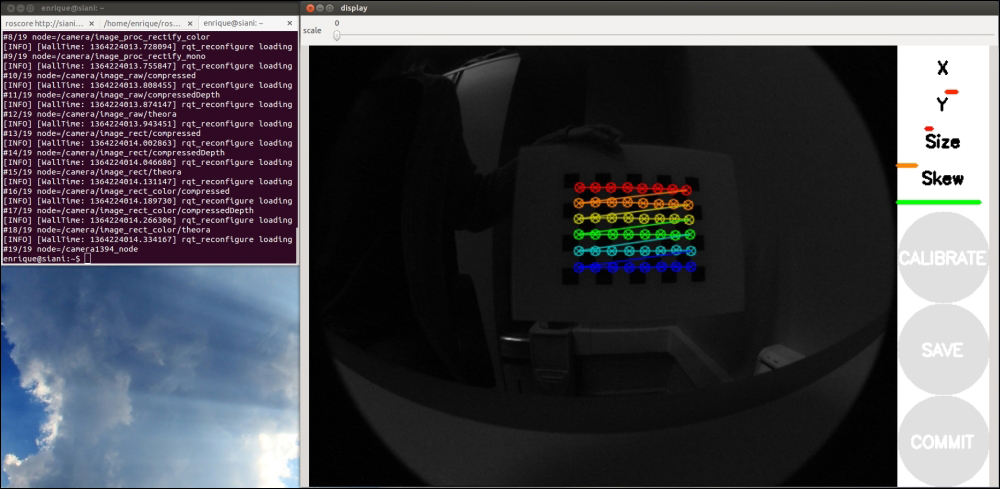
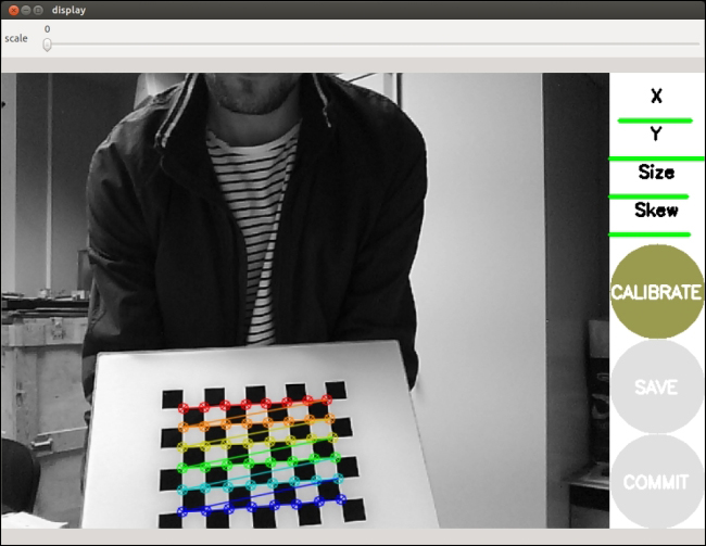
You will see the points detected overlaid over the pattern every time the detector finds them. The views are automatically selected to cover a representative number of different views, so you must show views to make the bars become green from one side to the other, following the instructions given in the following section. In theory, two views are enough, but in practice, around ten are usually needed. In fact, this interface captures even more (30 to 40). You should avoid fast movements because blurry images are bad for detection. Once the tool has enough views, it will allow you to calibrate, that is, to start the optimizer that, given the points detected in the calibration pattern views, solve the system of the pinhole camera model. This is shown in the following screenshot:

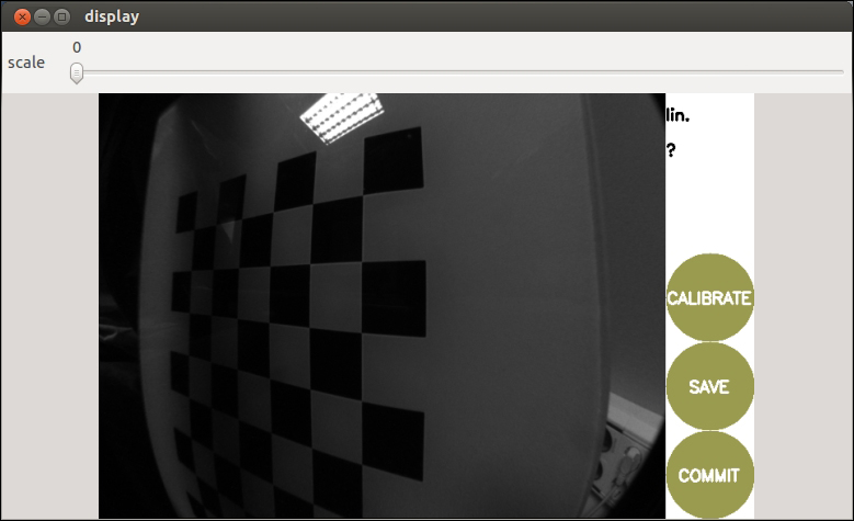
Then, you can save the calibration data and commit the calibration results to the camera, that is, it uses the camera_info_set service to commit the calibration to the camera, so later, it is detected automatically by the ROS image pipeline.
The launch file provided for the calibration simply uses cameracalibrator.py of the camera_calibration package:
<node pkg="camera_calibration" type="cameracalibrator.py"
  name="cameracalibrator" args="--size 8x6 --square 0.030"
  output="screen">
    <remap from="image" to="camera/image_color" />
    <remap from="camera" to="camera" />
</node>
The calibration tool only needs the pattern's characteristics (the number of squares and their size, --size 8x6 and --square 0.030 in this case), the image topic, and the camera namespace.
The launch file also runs the image pipeline, but it is not required. In fact, instead of the image_color topic, we could have used the image_raw one.
Once you have saved the calibration (save button), a file is created in your /tmp directory. It contains the calibration pattern views used for the calibration. You can find it at /tmp/calibrationdata.tar.gz; the ones used for the calibration in the book can be found in the calibration directory and the firewire_camera subfolder for the FireWire camera. Similarly, on the terminal (stdout output), you will see information regarding the views taken and the calibration results. The ones obtained for the book are in the same folder as the calibration data. The calibration results can also be consulted in the ost.txt file inside the calibrationdata.tar.gz ZIP file. Anyway, remember that, after the commit, the calibration file is updated with the calibration matrix and the coefficients of the distortion model. A good way to do so consists of on creating a dummy calibration file before the calibration. In our package, that file is in calibration/firewire_camera/calibration_firewire_camera.yaml, which is referenced by the parameters file:
camera_info_url: package://chapter5_tutorials/calibration/firewire_camera/calibration_firewire_camera.yaml
Now, we can use our camera again with the image pipeline, and the rectified images will have the distortion corrected as a clear sign that the camera is calibrated correctly. Since ROS uses the Zhang calibration method implemented in OpenCV, for more details on the calibration formulas, our advice is that you consult its documentation at http://docs.opencv.org/doc/tutorials/calib3d/camera_calibration/camera_calibration.html.
Finally, you can also play with different calibration patterns using the following launch files for circles and asymmetric circles (http://docs.opencv.org/_downloads/acircles_pattern.png), prepared for FireWire cameras, as an example:
roslaunch chapter5_tutorials calibration_firewire_camera_circles.launch
roslaunch chapter5_tutorials calibration_firewire_camera_acircles.launch
You can also use multiple chessboard patterns for a single calibration using patterns of different sizes. However, we think it is enough to use a single chessboard pattern printed with good quality. Indeed, for the USB camera driver, we only use that.
In the case of the USB camera driver, we have a more powerful launch file, which integrates the camera calibration node; there is also a standalone one for FireWire cameras, though. Hence, in order to calibrate your camera, use the following action:
$ roslaunch chapter5_tutorials camera.launch calibrate:=true
In the next screenshots, you can see the steps of the calibration process in the GUI, identical to the case of FireWire cameras. That means we have an operating camera_info_set service.
After pressing the calibrate button, the calibration optimization algorithm will take a while to find the best camera intrinsic and extrinsic parameters. Once it is done, the save and commit will be enabled. The following screenshot shows this:
The next step consists of working with stereo cameras. One option is to run two monocular camera nodes, but in general, it is better to consider the whole stereo pair as a single sensor because the images must be synchronized. In ROS, there is no driver for FireWire stereo cameras, but we can use an extension to stereo using the following command line:
$ git clone git://github.com/srv/camera1394stereo.git
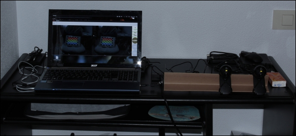
However, FireWire stereo pairs are quite expensive. For this reason, we provide a stereo camera driver for USB cameras. We use the Logitech C120 USB webcam, which is very cheap. It is also noisy, but we will see that we can do great things with it after we calibrate them. It is important that, in the stereo pair, the cameras are similar, but you can try with different cameras as well. Our setup for the cameras is shown in the images. You only need the two cameras on the same plane and pointing in parallel directions. We have a baseline of approximately 12 cm, which will also be computed in the stereo calibration process. As you can see in the following screenshot, you only need a rod to attach the cameras to, with zip ties:

Now, connect the cameras to your USB slots. It is good practice to connect the left-hand side camera first and then the right-hand side one. This way, they are assigned to the /dev/video0 and /dev/video1 devices, or 1 and 2 if 0 was already taken. Alternatively, you can create a udev rule.
Then, you can test each camera individually as we would do for a single camera. Some tools you will find useful are the video4linux control panels for cameras:
$ sudo apt-get install v4l-utils qv4l2
You might experience the following problem:
In case of problems with stereo:
libv4l2: error turning on stream: No space left on device
This happens because you must connect each camera to a different USB controller; note that certain USB slots are managed by the same controller and hence it cannot deal with the bandwidth of more than a single camera. If you only have a USB controller, there are other options you can try. First, try to use a compressed pixel format, such as MJPEG in both cameras. You can check whether it is supported by your camera or not using the following command:
$ v4l2-ctl -d /dev/video2 --list-formats
The command will generate something similar to the following output:
ioctl: VIDIOC_ENUM_FMT
Index       : 0
Type        : Video Capture
Pixel Format: 'YUYV'
Name        : YUV 4:2:2 (YUYV)

Index       : 1
Type        : Video Capture
Pixel Format: 'MJPG' (compressed)
Name        : MJPEG
If MJPEG is supported, we can use more than one camera in the same USB controller; otherwise, with uncompressed pixel formats, we must use different USB controllers or reduce the resolution to 320 x 240 or lower. Similarly, with the GUI of qv4l2, you can check this and test your camera. You can also check whether it is possible to set the desired pixel format. In fact, this does not work for our USB cameras using the OpenCV set method, so we use an USB slot managed by a different USB controller.
The USB stereo camera driver that comes with this book is based on the USB camera discussed so far. Basically, the driver extends the camera to support camera publishers, which send the left-hand side and right-hand side images and the camera information as well. You can run it and view the images by using the following command:
$ roslaunch chapter5_tutorials camera_stereo.launch view:=true
It also shows the disparity image of the left-hand side and right-hand side cameras, which will be useful once the cameras are calibrated since it is used by the ROS image pipeline. In order to calibrate the cameras, use the following command:
$ roslaunch chapter5_tutorials camera_stereo.launch calibrate:=true
You will see a GUI for monocular cameras similar to the following screenshot:

At the time the preceding image was taken, we showed enough views to start the calibration. Note that the calibration pattern must be detected by both cameras simultaneously to be included for the calibration optimization step. Depending on the setup, this may be quite tricky, so you should put the pattern at the appropriate distance from the camera. You can see the setup used for the calibration of this book in the next image:
The calibration is done by the same cameracalibrator.py node used for monocular cameras. We pass the left-hand side and right-hand side cameras and images, so the tool knows that we are going to do stereo calibration. The following is the node in the launch file:
<node ns="$(arg camera)" name="cameracalibrator"
  pkg="camera_calibration" type="cameracalibrator.py"
  args="--size 8x6 --square 0.030" output="screen">
    <remap from="left" to="left/image_raw"/>
    <remap from="right" to="right/image_raw"/>
    <remap from="left_camera" to="left"/>
    <remap from="right_camera" to="right"/>
</node>
The result of the calibration is the same as for monocular cameras, but in this case, we have two calibration files, one for each camera. In accordance with the parameters file in config/camera_stereo/logitech_c120.yaml, we have the following code:
camera_info_url_left: package://chapter5_tutorials/calibration/camera_stereo/${NAME}.yaml
camera_info_url_right: package://chapter5_tutorials/calibration/camera_stereo/${NAME}.yaml
${NAME} is the name of the camera, which resolved to logitech_c120_left and logitech_c120_right for the left-hand side and right-hand side cameras, respectively. After the commit of the calibration, those files are updated with the calibration of each camera. They contain the calibration matrix, the distortion model coefficients, and the rectification and projection matrix, which includes the baseline, that is, the separation between each camera in the x axis of the image plane. In the parameters file, you can also see values for the camera properties that have been set for indoor environments with artificial light; the camera model used has some autocorrection, so sometimes, the images may be quite bad, but these values seem to work well in most cases.