
In this section, we will go through the different steps required to get a robotic arm working with MoveIt! There are several elements that need to be provided beforehand, such as the arm description file (URDF), as well as the components required to make it work in Gazebo, although some of these will be covered in this chapter.
In order to make it easier to understand how we can integrate a robotic arm with MoveIt!, we have provided a set of packages containing all of the necessary configurations, robot descriptions, launch scripts, and modules to integrate MoveIt! with ROS, Gazebo, and RViz. We will not cover the details of how to integrate a robot with Gazebo as that has been covered in other chapters, but an explanation on how to integrate MoveIt! with Gazebo will be provided. The following packages are provided in the repository for this chapter, in the chapter10_tutorials directory:
chapter10_tutorials: This repository acts as a container for the rest of the packages that will be used in this chapter. This sort of structure usually requires a metapackage to let catkin know that the packages are loosely related; hence, this package is the metapackage of the repository.rosbook_arm_bringup: This package centralizes the launching of both the controllers and MoveIt! as well as theplay_motionutility, which can be used to request predefined arm configurations. It brings up the robot—either the real one or in simulation.rosbook_arm_controller_configuration: This package contains the launch files to load the controllers required to move the arm. These are trajectory (JointTrajectoryController) controllers used to support the MoveIt! motion planning.rosbook_arm_controller_configuration_gazebo: This package contains the configuration for the joint trajectory controllers. This configuration also includes the PID values required to control the arm in Gazebo.rosbook_arm_description: This package contains all of the required elements to describe the robotic arm, including URDF files (actually xacro), meshes, and configuration files.rosbook_arm_gazebo: This package is one of the most important packages, containing the launch files for Gazebo, which will take care of launching the simulation environment as well as MoveIt!, and the controllers, as well as taking care of running the launch files required (mainly calling the launch file inrosbook_arm_bringupbut also all the previous packages). It also contains the world's descriptions in order to include objects to interact with.rosbook_arm_hardware_gazebo: This package uses the ROS Control plugin used to simulate the joints in Gazebo. This package uses the robot description to register the different joints and actuators, in order to be able to control their position. This package is completely independent of MoveIt!, but it is required for the integration with Gazebo.rosbook_arm_moveit_config: This package is generated through the MoveIt! setup assistant. This contains most of the launch files required for both MoveIt! and the RViz plugins as well as several configuration files for MoveIt!.rosbook_arm_snippets: Except for the pick and place example, this package contains all of the snippets used throughout the chapter.rosbook_arm_pick_and_place: This package is the biggest and most complex example in the book, containing a demonstration of how you can perform object picking and placing with MoveIt!.
MoveIt! provides a user-friendly graphical interface for the purpose of integrating a new robotics arm into it. The setup assistant takes care of generating all of the configuration files and launch scripts based on the information provided by the user. In general, it is the easiest way to start using MoveIt! as it also generates several demonstration launch scripts, which can be used to run the system without a physical arm or simulation in place.
In order to launch the setup assistant, the following command needs to be executed in a terminal:
$ roslaunch moveit_setup_assistant setup_assistant.launch
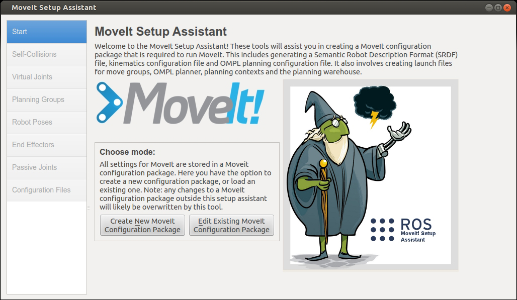
Figure 4: Initial screen of MoveIt! setup assistant
Once the command has been executed, a window similar to the one shown in Figure 4 should appear; in this particular case, the goal is to generate a new configuration, so that's the button we should aim for. Once the button has been pressed, the assistant will request a URDF or COLLADA model of the robotic arm, which, for our example arm, can be found in the following location inside the repository package:
rosbook_arm_description/robots/rosbook_arm_base.urdf.xacro
Please note that the robot description provided is in the XML Macros (Xacro) format, which makes it easier to generate complex URDF files. Once the robot description has been loaded, the reader needs to go through each tab, adding the required information. The first tab, as seen in Figure 5, is used to generate the self-collision matrix. Fortunately for the user, this process is performed automatically by simply setting the sampling density (or using the default value), and clicking on the Regenerate Default Collision Matrix button. The collision matrix contains information about how and when links collide in order to improve the performance of the motion planner. Figure 5 shows this in detail:
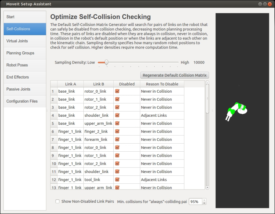
Figure 5: Self-collision tab of MoveIt! Setup Assistant
The second tab, as seen in Figure 6, is used to assign virtual joints to the robot. A virtual joint is used to attach the robotic arm to the world as the pose of a robot can vary with respect to it, but in this particular case, we won't need a virtual joint because the base of the arm does not move. We need virtual joints when the manipulator is not fixed in one place. In that case, for example, if the arm is on top of a mobile platform, we need a virtual joint for the odometry since base_link (base frame) moves with respect to the odom frame.

Figure 6: Virtual joints tab of MoveIt! Setup Assistant
In the third tab, which can be seen in Figure 7, we need to define the planning groups of the robotic arm. Planning groups, as the name suggests, are sets of joints that need to be planned together in order to achieve a given goal on a specific link or end effector. In this particular case, we need to define two planning groups: one for the arm itself and another for the gripper. The planning will then be performed separately for the arm positioning and the gripper action.
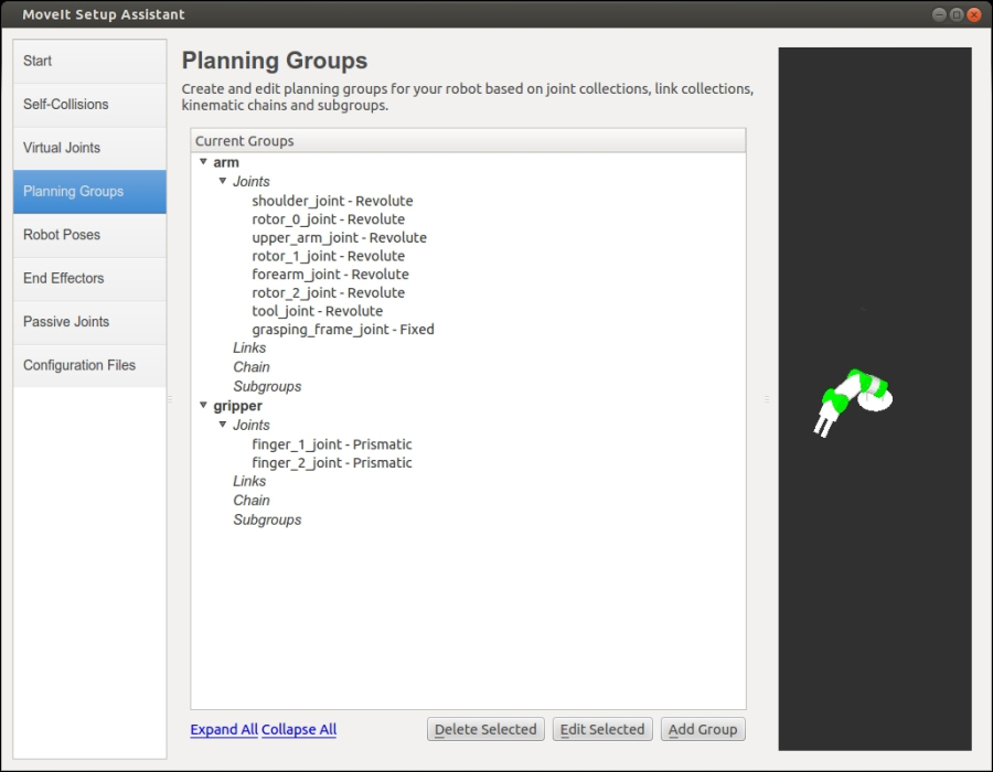
Figure 7: Planning Groups tab of MoveIt! Setup Assistant
The fourth tab, as shown on Figure 8, gives us the ability to define known robot poses in order to be able to reference them later; these predefined poses are also referred to as group states. As we can see, we have set up two different poses: the home position, which corresponds to the "stored" position of the arm, and the grasping position, which, as the name suggests, should allow the robot to grasp elements in the scene. Setting known poses can have multiple benefits in a real-life situation; for example, it is common to have an initial position from which planning happens, a position where the arm is safe to be stored in a container, or even a set of known positions with which to compare the position accuracy over time.
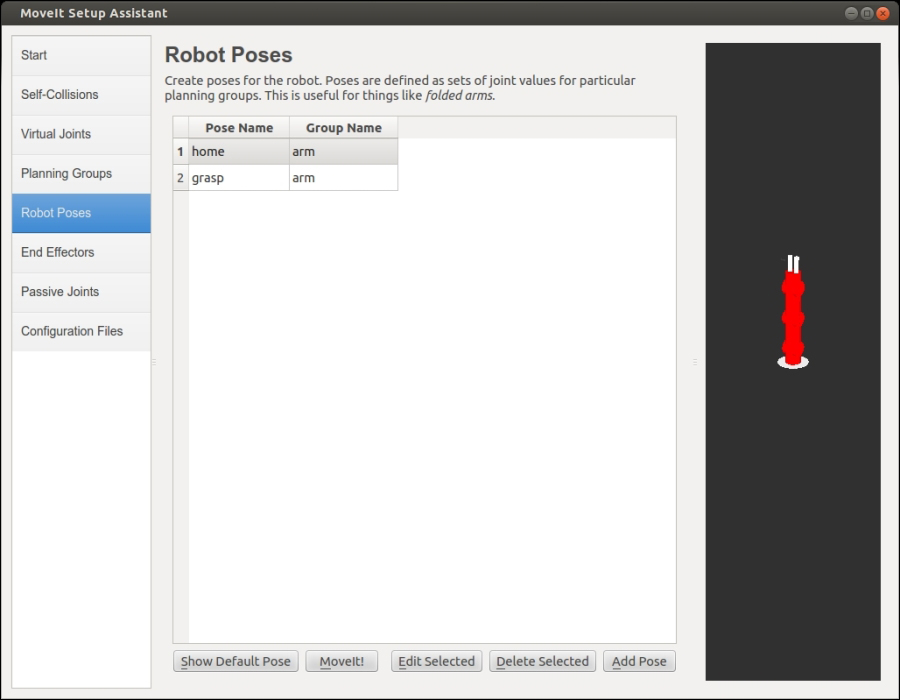
Figure 8:Robot Poses tab of MoveIt! Setup Assistant
The fifth tab, used to define the robotic arm's end effector, can be seen in Figure 9. As we discussed earlier, the robotic arm usually has an end effector, which is used to perform an action, such as a gripper or some other tool. In our case, the end effector is a gripper, which allows us to pick objects from the scene. In this tab, we need to define the gripper's end effector by assigning it a name, a planning group, and the parent link containing the end effector.
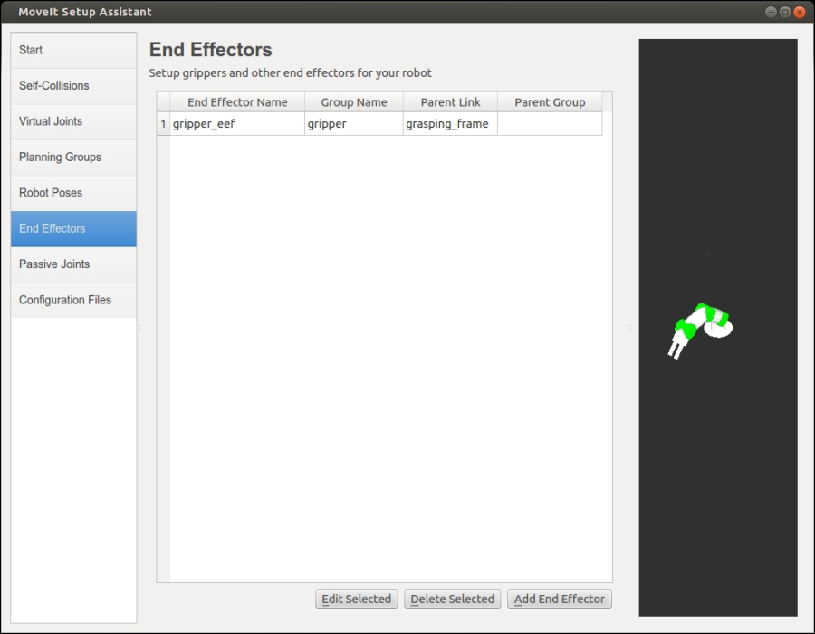
Figure 9: End effectors tab of MoveIt! Setup Assistant
The sixth tab, shown in Figure 10, is an optional configuration step, which allows us to define joints that cannot be actuated. An important feature of these joints is that MoveIt! doesn't need to plan for them and our modules don't need to publish information about them. An example of a passive joint in a robot could be a caster, but in this case, we'll skip this step as all of our passive joints have been defined as fixed joints, which will eventually produce the same effect on motion planning.

Figure 10: Passive Joints tab of MoveIt! Setup Assistant
Finally, as seen in Figure 11, the last step in the setup assistant is generating the configuration files. The only thing required in this step is to provide the path of the configuration package, which will be created by MoveIt!, and which will contain most of the launch and configuration files required to properly start controlling our robotic arm from MoveIt!
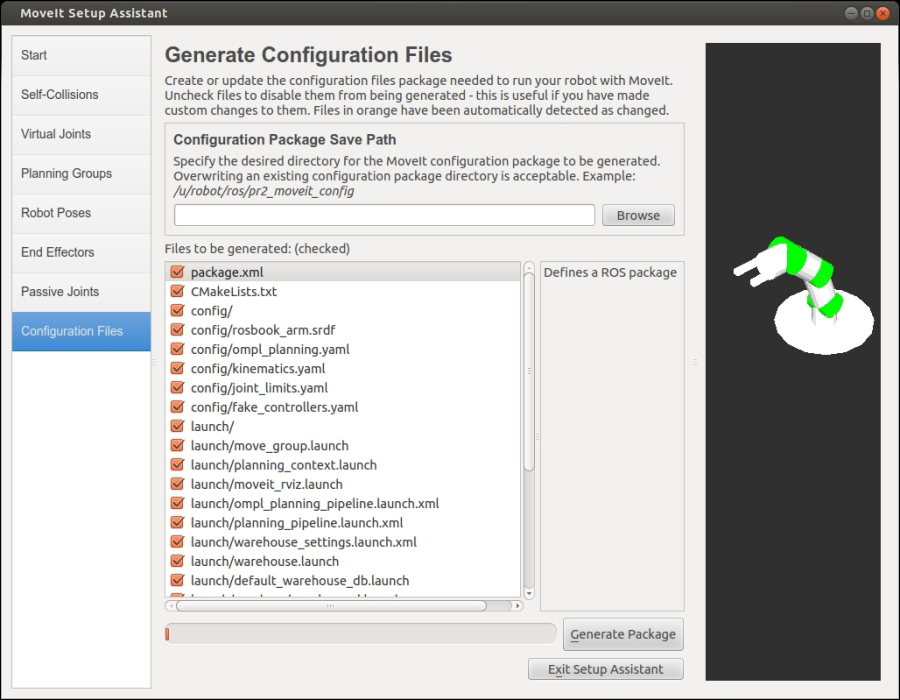
Figure 11: Generate Configuration Files tab of MoveIt! Setup Assistant
It is important to take into account that the configuration generated by the setup assistant has already been provided in the repository and that even though it is recommended that you go through the process, the result can be discarded in favor of the provided package, which is already being referenced by the rest of the launch scripts and configuration files in the repository.
MoveIt! provides a very useful and complete RViz plugin that gives the user the ability to perform several actions, such as plan different goals, add and remove objects to the scene, and so on. The setup assistant usually creates a number of launch files, among which there is one called demo, which takes care of launching MoveIt! as well as the fake controllers, RViz and the plugin. In order to start the demonstration, run the following command:
$ roslaunch rosbook_arm_moveit_config demo.launch
Once RViz launches, a motion planning panel should appear as well as the visualization of the robotic arm. The important tabs we need to consider are the Planning tab and the Scene objects tab. In the Planning tab, the user will be able to plan different goal positions, execute them, and set some of the common planning options. In the latter, objects can be inserted and removed from the planning scene.
Figure 12 shows the planning tab as well as a visualization of the robotic arm in both white and orange. The former is the current state of the arm, and the latter is the goal position defined by the user. In this particular case, the goal position has been generated using the tools in the Query panel. Once the user is happy with the goal state, the next step can be to either plan to visualize how the arm is going to move or plan to execute it to not only visualize the movement but also move the arm itself.

Figure 12: Planning tab and goal position visualization in RViz plugin
Other options, such as the planning time or the number of planning attempts, can be tweaked in order to account for complex goals, but for most of the cases in the demonstration, changing these parameters won't be required. Another important parameter is the goal tolerance, which defines how close to the goal position we require the robotic arm to be, in order to consider the position as having been achieved.
Planning random goals might be of some interest, but another level of planning is provided by the RViz plugin. As illustrated in Figure 13, the robotic arm visualization has a marker on the end effector. This marker allows us to position the end effector of the arm as well as rotate it on each axis. You can now make use of this marker to position the arm towards more interesting configurations.
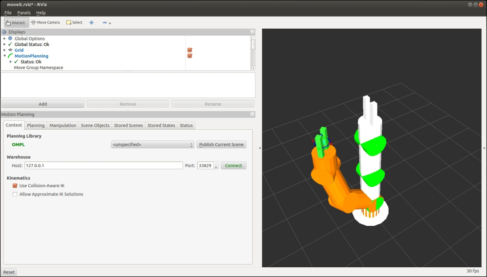
Figure 13: Using markers to set the goal position in RViz plugin
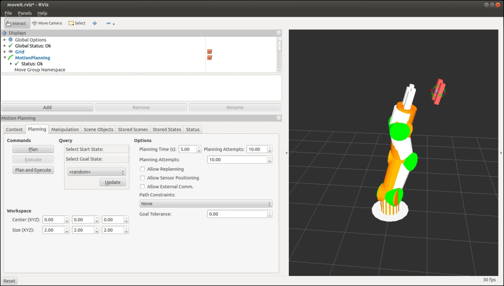
Figure 14: Markers out of bounds in RViz plugin
In many cases, planning by positioning the marker might produce no movement at all and show the robotic arm in the same position, but the marker and the end effector might be in other positions. An example of this behavior can be seen in Figure 14, and it usually happens when the desired position is out of the range of motion of the robotic arm (when there are not enough degrees of freedom, too many constraints, and so on). Similarly, when the arm is positioned in a state in which it collides with elements in the scene or with itself, the arm will show the collision zone in red. Finally, Figure 15 shows the different options provided by the MoveIt! plugin's visualization:
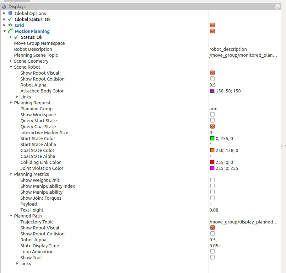
Figure 15: Motion planning plugin options in RViz plugin
As the names suggest, all of these options are meant to provide a way to tweak the visualization as well as add more information to it. Other interesting options that the user might want to modify are Trajectory Topic, which, as the name suggests, is the topic on which the visualization trajectory is published, and Query Start State, which will also show the state from which the arm is about to execute the plan. In most cases, the start state is usually the current state of the arm, but having a visualization cue can help spot issues in our algorithms.
The MoveIt! integration into Gazebo is a relatively straightforward process, which can be divided into two different steps: first of all, we need to provide all of the sensors required by MoveIt!, such as the RGBD sensor, so that motion planning can take the environment into account, and secondly, we also need to provide a controller as well as the current joint states periodically.
When a sensor is created in Gazebo, it interacts with the system as a normal sensor would by simply producing the required data. This data is then used by MoveIt! in exactly the same way that data produced by a real sensor would in order to generate collision artifacts in the planning scene. The process of making MoveIt! aware of those sensors will be explained later in this chapter.
As regards the manipulator's (arm and gripper) definition, a URDF description is provided using Xacro files as with any robot in ROS. In the case of using MoveIt!, we need to configure the controllers for the manipulator joints as JointTrajectoryController because the motion plans provide the output with messages for that type of controller. In the case of the manipulator used in this chapter, we need two controllers of this type: one for the arm and another for the gripper. The controller configuration is organized in the rosbook_arm_controller_configuration and rosbook_arm_controller_configuration_gazebo packages with the launch and config YAML files, respectively.
This type of controller is provided by the ROS control. Consequently, we need a RobotHardware interface for our arm to actually move in Gazebo or in the real hardware. The implementation is different for Gazebo and the real arm, and here we only provide the first. The rosbook_arm_hardware_gazebo package has the C++ implementation of RobotHardware for the manipulator used in this chapter. This is done by implementing the interface, so we create a new class that inherits from it. Then, the joints are properly handled, by writing the desired target positions (using position control) and reading the actual ones, along with the effort and velocity for each joint. For the sake of simplicity, we omit the explanation of the details of this implementation, which is not needed to understand MoveIt! However, if the number manipulator is drastically changed, the implementation must be changed although it is generic enough to detect the number of joints automatically from the robot description.