
7 The Malström: Close-Up
WHEN REASON 2.0 HIT THE MARKET IN 2002, Propellerhead introduced a new virtual synth, based on an original form of synthesis, called the Malström (see Figure 7.1). With its handsome graphical interface and unbelievable synthesis prowess, it is likely to quickly become a permanent fixture in your Reason songs.

© Propellerhead Software AB.
Graintable Synthesis
Malström’s uniqueness stems from the method by which it generates sound, called graintable synthesis, which is essentially a combination of granular and wavetable synthesis. To better understand how this works, you need to understand these two forms of synthesis.
In granular synthesis, sound is generated by a specific number of short, adjacent audio segments, called grains. Grains can be generated either by using a mathematical formula or by using a sample. These grains are usually 5–100 milliseconds long and are spliced together to form a sound. Altering the order of slices or modifying the individual properties of each slice can change the overall sound.
Wavetable synthesis is based on the playback of a set of single cycle waveforms. Wavetable synthesis offers a few key benefits, such as the capability to sweep through the wavetable at any speed without affecting the pitch, and quickly accessing specific points of the stored waveform data.
These two sound-generation techniques are very similar because they access stored audio data. Wavetable synthesis is always bound to a full periodic cycle, and the length of the audio segment is determined by the wavetable. With granular synthesis, the length of the audio segment is arbitrary and determined by a length parameter.
NOTE: For modern-day examples of both granular and wavetable synthesis, check out the Native Instruments Reaktor virtual synth.
As stated, graintable synthesis is a combination of these two forms of synthesis and works in the Malström as follows:
1. The oscillators of the Malström play sampled sounds that have been preprocessed in a complex manner and cut into individual grains. From this point on, these converted samples are called graintables.
2. These graintables are made up of periodic sets of waveforms that, when combined, play back the original sounds.
3. At this point, the graintable is treated in the same way as a wavetable. You have the ability to sweep through the graintable and single out any nuance of the graintable that you would like to manipulate. For example, you could extract a vowel out of a voice graintable. The graintable can be manipulated further by incorporating the ability to “shift” the frequency region or “formant” without altering the pitch, which is a granular synthesis quality.
Tour the Malström
Now that you have learned the fundamentals of graintable synthesis, load an instance of the Malström and take a tour of the interface. Before you begin this section, start a new Reason song and load an instance of the Malström.
The Oscillator Section
The Malström has two oscillators from which to generate sound (see Figure 7.2). The Malström’s oscillators are meant to perform two tasks:
![]() Play the loaded graintable.
Play the loaded graintable.
![]() Generate a pitch.
Generate a pitch.

© Propellerhead Software AB.
When you create an instance of the Malström, a default patch will load and can be heard by playing your keyboard. This is a good, solid sound to begin touring the Malström, but you can click on the Patch Browser located in the upper-left corner of the Malström interface and load patches from the Reason Factory Sound Bank. As was the case with other Reason instruments, Malström patches are organized by their intended use, including the following:
![]() Bass
Bass
![]() Effects
Effects
![]() Mono synths
Mono synths
![]() Pads
Pads
![]() Percussion
Percussion
![]() Poly synths
Poly synths
![]() Rhythmic
Rhythmic
Of course, none of these presets is set in stone, so to speak. You can modify a poly synth patch to be used as a pad, or a mono synth patch to be used as a bass synth. You just have to learn your way around the Malström and understand how each part of the interface works.
with that thought in mind, let’s continue onward by touring the individual sections of the Malström with a clean slate. Right-click on the interface and select Initialize Patch. This resets the Malström and gives you a good starting point.
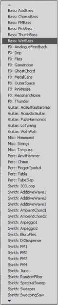
After you activate either of the oscillators, the next task is to select a graintable from the display just to the right of the Osc A and Osc B power buttons. You can select a graintable either by using the scroll buttons of the graintable display or by clicking on the display itself. If you click on the display, a pop-up menu will appear, displaying a long list of available graintables from which to choose (see Figure 7.3).
© Propellerhead Software AB.
Organization of the Graintables: As you begin to explore the long list of more than 80 graintables, it’s refreshing to see that Propellerhead has categorized these graintables by type. This arrangement makes it much easier when you’re beginning to build a new patch from scratch or when editing a patch.
The graintable list is organized as follows:
![]() Bass: Six graintables
Bass: Six graintables
![]() Effects: 10 graintables
Effects: 10 graintables
![]() Guitar: Five graintables
Guitar: Five graintables
![]() Misc: Three graintables
Misc: Three graintables
![]() Perc: Five graintables
Perc: Five graintables
![]() Synth: 22 graintables
Synth: 22 graintables
![]() Voices: 11 graintables
Voices: 11 graintables
![]() Wave: 10 graintables
Wave: 10 graintables
![]() Wind: 10 graintables
Wind: 10 graintables
Setting the Oscillator Frequency
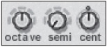
After selecting a graintable, you can alter the frequency of the oscillators by using a combination of three parameters (see Figure 7.4):
© Propellerhead Software AB.
![]() Octave: This alters the frequency of a graintable by octaves and has a range of seven octaves.
Octave: This alters the frequency of a graintable by octaves and has a range of seven octaves.
![]() Semi: This alters the frequency of a graintable by semitones and has a range of 12 semitones, or one full octave.
Semi: This alters the frequency of a graintable by semitones and has a range of 12 semitones, or one full octave.
![]() Cent: This alters the frequency of a graintable by cents. With a range of one semitone, it is used to make very fine adjustments to a loaded graintable.
Cent: This alters the frequency of a graintable by cents. With a range of one semitone, it is used to make very fine adjustments to a loaded graintable.
Altering the Oscillator Playback
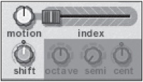
After setting the frequency of a graintable, you can alter the playback of the oscillators by using the Motion, Index, and Shift parameters (see Figure 7.5).
© Propellerhead Software AB.
![]() Index: This is used to set the start point for the playback of the graintable. It has a range of 0–127.
Index: This is used to set the start point for the playback of the graintable. It has a range of 0–127.
![]() Motion: This is used to set the speed at which a graintable is played, according to its motion pattern. Turning the knob to the left slows down the motion of the graintable, whereas turning it to the right speeds it up.
Motion: This is used to set the speed at which a graintable is played, according to its motion pattern. Turning the knob to the left slows down the motion of the graintable, whereas turning it to the right speeds it up.
![]() Shift: This alters the timbre or formant spectrum of a graintable. The formant spectrum is the overview that determines the overall character of a graintable. This is done by a procedure known as resampling. Using this parameter effectively creates a pitch-shift effect on the oscillator.
Shift: This alters the timbre or formant spectrum of a graintable. The formant spectrum is the overview that determines the overall character of a graintable. This is done by a procedure known as resampling. Using this parameter effectively creates a pitch-shift effect on the oscillator.
Motion Pattern: Each graintable in a patch has a preset motion pattern and speed. If you’re setting the Motion parameter to any value higher than −63 or hard left, the graintable loops and follows one of two motion patterns:
![]() Forward: The graintable is played from beginning to end and then loops back to the beginning.
Forward: The graintable is played from beginning to end and then loops back to the beginning.
![]() Forward/Backward: The graintable is played from beginning to end and then from the end to beginning. It then starts over.
Forward/Backward: The graintable is played from beginning to end and then from the end to beginning. It then starts over.
As stated, the Motion parameter can change the speed of the graintable but not the actual graintable itself.
The Amplitude Envelope
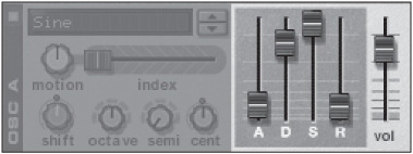
Each of the Malström oscillators has an individual envelope and volume knob to alter its amplitude (see Figure 7.6).
© Propellerhead Software AB.
![]() Attack: When an enveloped is triggered, the Attack parameter determines how long it takes for the envelope to reach its maximum value.
Attack: When an enveloped is triggered, the Attack parameter determines how long it takes for the envelope to reach its maximum value.
![]() Decay: Once the maximum value is reached, the Decay parameter determines how long it stays at the level before the value begins to drop.
Decay: Once the maximum value is reached, the Decay parameter determines how long it stays at the level before the value begins to drop.
![]() Sustain: After the value begins to drop, the Sustain parameter determines the level where the falling value should rest.
Sustain: After the value begins to drop, the Sustain parameter determines the level where the falling value should rest.
![]() Release: Once the value has been set at its rested value, the Release parameter determines how long it will take for the value to return to zero after the keys have been released.
Release: Once the value has been set at its rested value, the Release parameter determines how long it will take for the value to return to zero after the keys have been released.
Routing and Output
Once you have set the oscillator parameters, you can route the output of those signals to a combination of filter destinations. Looking at Figure 7.7, you can see that each oscillator points to the right, with a corresponding “routing” button that looks a lot like the standard power buttons you have been looking at throughout this chapter. To route the oscillators to their corresponding filters, just click on the available routing buttons.
© Propellerhead Software AB.
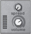
The Output section of the Malström is simple, having only two adjustable parameters (see Figure 7.8).
© Propellerhead Software AB.
![]() Spread: This parameter is used to adjust the panning width of Osc A and Osc B. Turning this knob hard right creates a wide stereo field, in which Osc A is heard only in the left channel, whereas Osc B is heard in the right.
Spread: This parameter is used to adjust the panning width of Osc A and Osc B. Turning this knob hard right creates a wide stereo field, in which Osc A is heard only in the left channel, whereas Osc B is heard in the right.
![]() Volume: This parameter adjusts the overall volume of the Malström.
Volume: This parameter adjusts the overall volume of the Malström.
The Filter Section
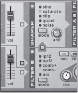
As any aspiring electronic musician knows, a filter is used to alter the overall character of a sound. The Filter section of the Malström does this tenfold by including additional filters and parameters that deviate significantly from most other filters (see Figure 7.9).
To activate Filter A or Filter B, click on their power buttons, found in the upper-left corner of each filter. Also, make sure that the appropriate oscillator is assigned to the desired filter.
Filter Types
Before altering the Resonance and Cutoff Frequency parameters, you must choose one of five filter types (see Figure 7.10).

© Propellerhead Software AB.

© Propellerhead Software AB.
![]() LP12: This filter allows low frequencies to pass through it, while high frequencies are filtered out. This low-pass filter has a roll-off curve of approximately 12 dB per octave.
LP12: This filter allows low frequencies to pass through it, while high frequencies are filtered out. This low-pass filter has a roll-off curve of approximately 12 dB per octave.
![]() BP12: This filter type filters out both the high and low frequencies, leaving the mid frequencies alone to be toyed with. With a roll-off curve of 12 dB per octave, the BP 12 can be used effectively on instrument loops such as guitar loops or possibly hi-hatheavy percussion loops.
BP12: This filter type filters out both the high and low frequencies, leaving the mid frequencies alone to be toyed with. With a roll-off curve of 12 dB per octave, the BP 12 can be used effectively on instrument loops such as guitar loops or possibly hi-hatheavy percussion loops.
![]() Comb +/−: A comb filter is essentially a series of delays with very short delay times assigned to each delay instance, resulting in a detuned sound. The feedback of these delays is controlled by the Resonance parameter in each filter, and the delay time is controlled (inversely) by the Filter Frequency knob. The difference between the Comb+ and Comb− is the position of the delay peaks within the spectrum.
Comb +/−: A comb filter is essentially a series of delays with very short delay times assigned to each delay instance, resulting in a detuned sound. The feedback of these delays is controlled by the Resonance parameter in each filter, and the delay time is controlled (inversely) by the Filter Frequency knob. The difference between the Comb+ and Comb− is the position of the delay peaks within the spectrum.
![]() AM (Amplitude Modulation): This filter produces a sine wave, which is then multiplied by the output of Osc A or Osc B. The resulting sound contains additional frequencies that are a result of the sum and difference of the two frequencies. Note that the Resonance knob controls the mix between the two signals. If this description sounds familiar, another way to think of this is as a ring modulator.
AM (Amplitude Modulation): This filter produces a sine wave, which is then multiplied by the output of Osc A or Osc B. The resulting sound contains additional frequencies that are a result of the sum and difference of the two frequencies. Note that the Resonance knob controls the mix between the two signals. If this description sounds familiar, another way to think of this is as a ring modulator.
The Filter Controls
Once you have selected a filter type, you can then use the main controls of the filter to alter the character of the Malström patch (see Figure 7.11).

© Propellerhead Software AB.
![]() Kbd (Keyboard Tracking): When this is activated, it enables the filter to react differently the higher you play on the keyboard. If this parameter is deactivated, the filter effect will remain constant.
Kbd (Keyboard Tracking): When this is activated, it enables the filter to react differently the higher you play on the keyboard. If this parameter is deactivated, the filter effect will remain constant.
![]() Env (Envelope): When this is activated, the filter will be modulated by the Filter Envelope.
Env (Envelope): When this is activated, the filter will be modulated by the Filter Envelope.
![]() Freq (Cutoff Frequency): This has two purposes, depending on which filter type is selected. When LP24, BP12, or Comb+/− is selected, this parameter acts as a cutoff frequency knob that specifies where the filter will function within the frequency spectrum. When the AM filter type is selected, the Frequency knob controls the frequency of the ring-modulated signal generated by the AM filter.
Freq (Cutoff Frequency): This has two purposes, depending on which filter type is selected. When LP24, BP12, or Comb+/− is selected, this parameter acts as a cutoff frequency knob that specifies where the filter will function within the frequency spectrum. When the AM filter type is selected, the Frequency knob controls the frequency of the ring-modulated signal generated by the AM filter.
![]() Res (Resonance): This parameter has two purposes depending on which filter type is selected. When LP12, BP12, or Comb+/− is selected, this parameter emphasizes the frequencies set by the Freq knob. When the AM filter type is selected, the Resonance knob regulates the balance between the original and the modulated signal.
Res (Resonance): This parameter has two purposes depending on which filter type is selected. When LP12, BP12, or Comb+/− is selected, this parameter emphasizes the frequencies set by the Freq knob. When the AM filter type is selected, the Resonance knob regulates the balance between the original and the modulated signal.
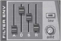
The Filter Envelope
The Filter Envelope is used to alter the characteristics of both Filter A and Filter B. The main parameters of the envelope match those of the oscillator envelopes, so there is no need to review how Attack, Decay, Sustain, and Release work (see Figure 7.12). The additional parameters for the Filter Envelope are as follows:
© Propellerhead Software AB.
![]() Inv (Inverse): This button is used to invert the individual parameters of the filter envelope. For example, say you are using the Attack parameter of the filter envelope and have assigned a value of 80, which produces a very slow attack. Activate the Invert button and the attack parameter is inverted, which means the attack will be much faster.
Inv (Inverse): This button is used to invert the individual parameters of the filter envelope. For example, say you are using the Attack parameter of the filter envelope and have assigned a value of 80, which produces a very slow attack. Activate the Invert button and the attack parameter is inverted, which means the attack will be much faster.
![]() Amt (Amount): This knob is used to assign the amount of envelope to the filters.
Amt (Amount): This knob is used to assign the amount of envelope to the filters.
The Shaper
In addition to the obvious auditory goodies that the Filter section provides, take a moment to focus on the small but mighty Shaper. The Shaper is a waveshaper, which alters the waveform shape itself. This results in either a more complex, rich sound or a truncated distortion that rivals industrial music on a good day.
You activate the Shaper by clicking on its power button, located in the upper-left corner of the Shaper interface. Once it is activated, you can edit the waveshaping effect by selecting a mode and assigning an amount.
Let’s look at the different shaping modes. You can select them by using the Mode button or by just clicking on the name of the desired mode itself (see Figure 7.13).

Figure 7.13
© Propellerhead Software AB.
![]() Sine: This creates a smooth sound.
Sine: This creates a smooth sound.
![]() Saturate: This saturates the original signal, resulting in a rich, lush sound.
Saturate: This saturates the original signal, resulting in a rich, lush sound.
![]() Clip: This adds digital distortion to the signal.
Clip: This adds digital distortion to the signal.
![]() Quant: This truncates the signal and can be used to create a grungy 8-bit sound.
Quant: This truncates the signal and can be used to create a grungy 8-bit sound.
![]() Noise: This multiplies the original signal with noise.
Noise: This multiplies the original signal with noise.
TIP: Located at the top of Filter B is a routing button that allows that filter to be sent to the Shaper, creating an interesting combination of sounds. For example, you can send Osc A to the Shaper and at the same time split and send Osc A to Filter B. Osc B will also be sent to Filter B and then routed to the Shaper as well. After both signals are combined and processed by the Shaper, the signal is then sent to Filter A and sent along to the outputs of the Malström.
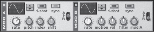
The Modulator Section
Located above the Oscillator section is a pair of modulators, which are used to alter the character of the synth sound (see Figure 7.14). If this description sounds familiar, another way to think of these modulators is as low-frequency oscillators (LFOs). However, because the Malström is a synth unlike anything else in Reason, it’s safe to say that these modulators go way above and beyond the call of duty when it comes to modulating the oscillators.
© Propellerhead Software AB.
TIP: As with the SubTractor and Dr. Octo Rex, the Malström modulators do not produce sound on their own. Although they do generate a waveform and frequency, they are assigned to alter the character of Osc A and Osc B.
when an instance of the Malström is created, modulators A and B are active and ready to use. To deactivate either of these, click on their power buttons, which are located at the upper-left corner of each modulator.
Take a look at the source parameters of the Modulator section.
![]() Curve: This is used to select a modulating waveform. The selected waveform is shown in the Curve display window. You can either use the scroll buttons to select different waveforms or click and drag up and down on the display. There are more than 30 waveforms from which to choose, so it should keep you busy for a long time to come.
Curve: This is used to select a modulating waveform. The selected waveform is shown in the Curve display window. You can either use the scroll buttons to select different waveforms or click and drag up and down on the display. There are more than 30 waveforms from which to choose, so it should keep you busy for a long time to come.
![]() Rate: This controls the speed of modulation. Turn the knob to the left to slow down the frequency or to the right to speed it up. Also note that if the Sync button is activated, the rate indicator is measured in note values (that is, 1/4, 1/8, and 1/16).
Rate: This controls the speed of modulation. Turn the knob to the left to slow down the frequency or to the right to speed it up. Also note that if the Sync button is activated, the rate indicator is measured in note values (that is, 1/4, 1/8, and 1/16).
![]() One Shot: When activated, the One Shot parameter plays the modulation waveform a single time.
One Shot: When activated, the One Shot parameter plays the modulation waveform a single time.
![]() Sync: This makes the modulator synchronize with the tempo of your Reason song.
Sync: This makes the modulator synchronize with the tempo of your Reason song.
![]() A/B Selector: This is used to select which oscillator the modulator will affect. You can select Osc A, Osc B, or both.
A/B Selector: This is used to select which oscillator the modulator will affect. You can select Osc A, Osc B, or both.
After selecting a modulation waveform, rate and a source, you can choose a destination parameter to be modulated. Note that both modulators have different destination parameters, so I will point them out along the way.
TIP: The destination parameter knobs are bipolar. That means when the knob is in the middle position, there is no modulation effect, but turning the knob to the left or right increases the amount of modulation. To make it even more interesting, when the knob is turned to the left, the waveform of the modulator is inverted.
![]() Pitch (Mod A): This modulates the pitch parameter of Osc A, Osc B, or both.
Pitch (Mod A): This modulates the pitch parameter of Osc A, Osc B, or both.
![]() Index (Mod A): This modulates the index start position of Osc A, Osc B, or both.
Index (Mod A): This modulates the index start position of Osc A, Osc B, or both.
![]() Shift (Mod A): This modulates the harmonic content of Osc A, Osc B, or both.
Shift (Mod A): This modulates the harmonic content of Osc A, Osc B, or both.
![]() Motion (Mod B): This modulates the motion speed of Osc A, Osc B, or both.
Motion (Mod B): This modulates the motion speed of Osc A, Osc B, or both.
![]() Level (Mod B): This modulates the output amplitude of Osc A, Osc B, or both.
Level (Mod B): This modulates the output amplitude of Osc A, Osc B, or both.
![]() Filter (Mod B): This modulates the cutoff filter of Osc A, Osc B, or both.
Filter (Mod B): This modulates the cutoff filter of Osc A, Osc B, or both.
![]() Mod:A (Mod B): This alters the amount of modulation from Mod A.
Mod:A (Mod B): This alters the amount of modulation from Mod A.
The Keyboard Mode Parameters
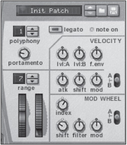
The parameters covered in this section affect the overall sound of the Malström based on the way you play the synth (see Figure 7.15).
© Propellerhead Software AB.
Polyphony
Polyphony assigns the number of voices that can be played at one time. The Malström has a polyphony range of 1–16 voices, which is not a lot by comparison to the SubTractor or NN-19/XT synths. However, it is important to keep in mind that the Malström is a much more CPU-intensive virtual synth, and every voice takes a little more CPU power.
NOTE: One feature that the Malström is missing is a Low Bandwidth button. There is no explanation why this feature is not included with the Malström, but perhaps the technology behind this synth wonder makes it impossible to support such a feature. I have run Malström with no problems on a pair of fairly slow computers. But keep in mind that the slower the computer, the more trouble you might have running the Malström.
Portamento
Portamento creates a sliding effect between played notes. The knob determines the amount of time it will take to slide from one note to another. It can be used with either monophonic or polyphonic patches and is a great tool for creating some interesting effects.
Legato
Legato is a commonly used parameter for playing monophonic patches, such as leads or bass lines. With the Legato parameter activated and Polyphony set to 1, press and hold down a note, and then press and hold another note. Notice that the new note has no attack because the Malström envelopes have not been retriggered.
Velocity Controls
The Malström is a velocity-sensitive synthesizer, as are the other Reason synths. The Velocity controls are used to affect different parameters of the Malström according to how much velocity is applied to individual notes.
![]() Level A: This parameter velocity controls the output of Osc A.
Level A: This parameter velocity controls the output of Osc A.
![]() Level B: This parameter velocity controls the output of Osc B.
Level B: This parameter velocity controls the output of Osc B.
![]() Filter Envelope: This parameter assigns the velocity control of the Filter Envelope.
Filter Envelope: This parameter assigns the velocity control of the Filter Envelope.
![]() Attack: This parameter velocity controls the Attack parameter of Osc A, Osc B, or both.
Attack: This parameter velocity controls the Attack parameter of Osc A, Osc B, or both.
![]() Shift: This parameter velocity controls the Shift parameter of Osc A, Osc B, or both.
Shift: This parameter velocity controls the Shift parameter of Osc A, Osc B, or both.
![]() Modulation: This parameter velocity controls the amounts of Mod A, Mod B, or both.
Modulation: This parameter velocity controls the amounts of Mod A, Mod B, or both.
Pitch Bend Wheel
The Pitch Bend wheel is an emulation of a standard pitch wheel found on most MIDI keyboards. Simply put, it is used to bend up and down the pitch of the played notes. The Range parameter, located just above the Pitch Bend wheel, controls the range of the pitch bend by up to +/− two octaves.
Mod Wheel
The Mod Wheel setting is used to control a number of available parameters:
![]() Index: This affects the graintable index of Osc A, Osc B, or both.
Index: This affects the graintable index of Osc A, Osc B, or both.
![]() Shift: This affects the Shift parameter of Osc A, Osc B, or both.
Shift: This affects the Shift parameter of Osc A, Osc B, or both.
![]() Filter: This affects the Frequency filter of Filter A, Filter B, or both.
Filter: This affects the Frequency filter of Filter A, Filter B, or both.
![]() Modulation: This alters the amount of modulation from Mod A, Mod B, or both.
Modulation: This alters the amount of modulation from Mod A, Mod B, or both.
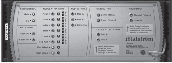
CV Connections
Press the Tab key to flip the Rack screen around, and you’ll see that the Malström has many connections that can be used to sequence with the Matrix, to modulate other devices, or to be modulated by other devices (see Figure 7.16).
© Propellerhead Software AB.
Audio Outputs
The audio connections are used to output the signal from the Malström to the mixer. There are a couple of options:
![]() Main outputs: These are the main audio outputs of the Malström. They are taken from the outputs of the Filter section.
Main outputs: These are the main audio outputs of the Malström. They are taken from the outputs of the Filter section.
![]() Oscillator outputs: This second pair of outputs is taken directly from the outputs of Osc A and Osc B. If you connect these outputs to reMix, the main outputs will no longer work.
Oscillator outputs: This second pair of outputs is taken directly from the outputs of Osc A and Osc B. If you connect these outputs to reMix, the main outputs will no longer work.
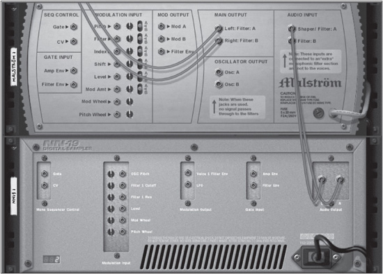
Audio Input
Another of the many lesser-known, yet equally mind-blowing, features of the Malström is its audio input capabilities. These inputs make it possible to route the audio output of any Reason device into the audio inputs of the Malström, which are then directly fed into Filter A and Filter B. Essentially, this makes the Malström an audio effect that is perfect for laying down some intense filter work on your loops, synths, and samples, or even your guitar!
For kicks, try the following exercise:
1. Create a new Reason song.
2. Create instances of the Malström and NN-19. Load a sample patch into the NN-19 and arm the sequencer track to receive MIDI.
3. Press the Tab key to flip the interface.
4. Disconnect the NN-19 from the mixer by selecting it and choosing Disconnect Device from the Edit menu.
5. Route the audio outputs of the NN-19 to the audio inputs of the Malström (see Figure 7.17).
6. With the NN-19 sequencer track selected and armed to receive MIDI, play a note on your MIDI keyboard, and you will hear the sample patch played through the filters of the Malström.
Seq Controls
The Seq (Sequencer) Control inputs are used to connect the Malström to a pattern-controlled device, such as the Matrix or Redrum. These inputs are as follows:
![]() Gate: This input is typically connected to the gate CV output of the Matrix or Redrum to receive Note On/Off messages.
Gate: This input is typically connected to the gate CV output of the Matrix or Redrum to receive Note On/Off messages.
![]() CV: This input is typically connected to the note CV output of the Matrix to receive note information.
CV: This input is typically connected to the note CV output of the Matrix to receive note information.
© Propellerhead Software AB.
Gate Input
The Gate inputs are used to receive gate information from either the Matrix or Redrum to trigger the amp envelope and filter envelope.
Modulation Input/Output
To the right of the Sequencer Control and Gate Input sections are the Modulation Input and Mod Output sections. The Modulation inputs can receive modulation output signals from any Reason device. The Curve CV output on the back of the Matrix is a good example of this. The Mod outputs send out modulation information to any Reason device. A commonly used connection is to connect any of the Mod outputs of the Malström to the Modulation inputs of the SubTractor or Thor.
Take a look at the various inputs:
![]() Pitch: This input is used to affect the pitch of Mod A, Mod B, or both.
Pitch: This input is used to affect the pitch of Mod A, Mod B, or both.
![]() Filter: This input is used to affect the filter frequency of Mod A, Mod B, or both.
Filter: This input is used to affect the filter frequency of Mod A, Mod B, or both.
![]() Index: This input is used to affect the index of Mod A, Mod B, or both.
Index: This input is used to affect the index of Mod A, Mod B, or both.
![]() Shift: This input is used to affect the shift of Mod A, Mod B, or both.
Shift: This input is used to affect the shift of Mod A, Mod B, or both.
![]() Level: This input is used to affect the amplitude of Osc A, Osc B, or both.
Level: This input is used to affect the amplitude of Osc A, Osc B, or both.
![]() Modulation Amount: This input is used to affect the amount of modulation.
Modulation Amount: This input is used to affect the amount of modulation.
![]() Modulation Wheel: This input is used to affect the amount of mod wheel.
Modulation Wheel: This input is used to affect the amount of mod wheel.
![]() Pitch Wheel: This input is used to affect the amount of pitch.
Pitch Wheel: This input is used to affect the amount of pitch.
And now, take a look at the outputs:
![]() Mod A: This connection routes the output of Mod A to the modulation inputs of any other Reason device. Try connecting it to the FM Amount parameter of the SubTractor.
Mod A: This connection routes the output of Mod A to the modulation inputs of any other Reason device. Try connecting it to the FM Amount parameter of the SubTractor.
![]() Mod B: This connection routes the output of Mod B to the modulation inputs of any Reason device.
Mod B: This connection routes the output of Mod B to the modulation inputs of any Reason device.
![]() Filter Envelope: This connection routes the output of the Filter Envelope to the modulation inputs of any Reason device.
Filter Envelope: This connection routes the output of the Filter Envelope to the modulation inputs of any Reason device.
Your First Malström Patch
Now that you have a pretty firm idea of how the Malström works, it’s time to dig in and create your first customized Malström patch. This tutorial takes you through a step-by-step process of programming a bass synth patch that will be perfect for any ambient occasion.
Setting Up a Starting Point
Before you program your first Malström patch, it’s important to find a good starting point. Writing in a sequence that’s appropriate for the kind of patch you are going to create will make the programming process quicker and more efficient. For example, if you were going to create a pad sound, you would typically want to write in a sequence of long, sustained chords so you could hear the pad sound properly.
If you are planning to program a bass synth patch to be used in techno music, it’s a good idea to write in a standard techno bass line in the Reason sequencer. Then set the sequencer to play the bass line over and over again in a loop. Then you can make real-time adjustments to the patch as the sequence is playing and program the patch to complement the style of music you are going to create with the patch.
Programming Your Malström Patch
In this tutorial, you are going to go build a bass patch by working with each section of the Malström interface. This tutorial serves as a good review tool to help you remember everything you have learned about the functionality of the Malström.
Programming the Oscillators
Let’s start things off simple by working with Osc A and then add Osc B later. To hear the changes in real time, click Play on the transport bar. The two-bar loop should start playing continuously.
1. By default, the graintable of Osc A is set to a sine wave. Notice the organ-like tone that is produced.
2. Use the scroll buttons or click on the graintable box to display a list of available sounds. Choose the Wet Bass graintable.
3. Use the Index slider to set the start point of the graintable to 40. Notice how dramatically the overall tone and timbre of the graintable changes.
Let’s also make a few adjustments to the Amplitude Envelope of Osc A. Set the parameters to the following values:
![]() Attack: 0
Attack: 0
![]() Decay: 65
Decay: 65
![]() Sustain: 0
Sustain: 0
![]() Release: 14 (for a short release)
Release: 14 (for a short release)
And now, on to Osc B:
1. Activate Osc B and set its graintable to Synth: Additive Wave 3.
2. Set the Motion parameter to 7.
3. Set the Octave parameter to 3.
4. Set the Index slider to 48.
Let’s make a few adjustments to the Amplitude Envelope of Osc B. Set the parameters to the following values:
![]() Attack: 12
Attack: 12
![]() Decay: 25
Decay: 25
![]() Sustain: 16
Sustain: 16
![]() Release: 10
Release: 10
Upon listening to the patch at this point, you will realize it lacks uniqueness. You can introduce such a quality by way of the modulators.
Programming the Modulators
As you read earlier in this chapter, the modulators are actually two separate LFOs. In this section of the tutorial, you are going to assign the modulators to manipulate Osc A and Osc B.
1. Activate Mod A and select the Sync button. This will lock up the modulation effect with the tempo of the Reason sequencer.
2. By default, the waveform of Mod A should be set to a sine wave. Leave it at this setting and set the Rate knob to 1/4, which means that the modulation effect will take place every 1/4 note.
3. Set the destination of Mod A to Osc A and Osc B by using the A/B selector to the right of the Mod A interface.
4. Assign a value of −24 to the Index knob. This should cause the Shift parameter of Osc A and Osc B to open and close in tempo.
Programming the Filter and Shaper
In this section of the tutorial, you are going to add the Shaper to Osc A to introduce a little distortion to the bass sound.
1. Activate both the Route Oscillator A to Shaper and Activate Shaper buttons.
2. Select Saturate Shaper mode by using the Mode button or by clicking on the name. You should immediately hear a strong distorted signal applied to Osc A.
3. Set the Shaper Amount knob to 39 to turn down the distortion effect.
Next, you’ll route Osc B to Filter B and do some more damage:
1. Activate the Route Oscillator B to Filter B button. Filter B should already be activated and ready to use. Also note that the Env button is already active, which means that the Filter Envelope can be used at this time.
2. Set Filter mode to Comb− by using the Mode button or by clicking on the name.
3. Set the Resonance knob to 70.
4. Set the Frequency Filter knob to 99.
You can also assign Osc A to Filter B by clicking on the Route Osc A to Filter B button. I suggest not activating it for this tutorial because Osc A has a very strong signal of its own.
Additionally, you can route Filter B to the Shaper by clicking on the Route Filter B to Shaper button, which is located between Filter B and the Shaper sections. This will add a pleasant distortion to Filter B, which sounds pretty cool.
To finish with the Filter and Shaper sections, use the Filter Envelope on Filter B. Set the envelope parameters to these values:
![]() Amount: 32
Amount: 32
![]() Attack: 38
Attack: 38
![]() Decay: 59
Decay: 59
![]() Sustain: 64
Sustain: 64
![]() Release: 10
Release: 10
Programming the Keyboard Mode Parameters
You’re in the home stretch. You can finish this patch by making a few adjustments to the Keyboard Mode parameters of the Malström, as follows:
![]() Polyphony: By default, the Malström has Polyphony set to 8, and this setting is fine for a bass synth sound. You might even want to set Polyphony to 1 so that you can make this a monophonic synth.
Polyphony: By default, the Malström has Polyphony set to 8, and this setting is fine for a bass synth sound. You might even want to set Polyphony to 1 so that you can make this a monophonic synth.
![]() Mod Wheel: Set the A/B Selector to its default position. Assign a negative value to the Shift knob in the Mod Wheel section so it will decrease in value as the mod wheel is used. Assign a positive value to the Index knob in the Mod Wheel section.
Mod Wheel: Set the A/B Selector to its default position. Assign a negative value to the Shift knob in the Mod Wheel section so it will decrease in value as the mod wheel is used. Assign a positive value to the Index knob in the Mod Wheel section.
![]() Portamento: Assigning a value of 34 to this parameter will create a sliding effect that sounds great with monophonic bass synths.
Portamento: Assigning a value of 34 to this parameter will create a sliding effect that sounds great with monophonic bass synths.
After all is said and done, your new bass patch should sound pretty awesome and work well with just about any form of electronic music. Just make sure to click on the Save Patch button to save your work.
For the bold explorers out there, I suggest some free-form experimentation. Sequence a short loop, start it playing, and then use your ears as you switch graintables and adjust the Motion, Shift, Index, Shaper, Modulation, and Filter parameters. You will quickly find that there are no upper (or outer) limits to what weird and wonderful sounds you can create.
Moving On
As you have seen in this chapter, the Malström is a true synthetic playground with nearly limitless creative possibilities. In the next chapter, you’ll get to say hello to the synth god of thunder, Thor!