
8 Thor: Close-Up
WHEN IT COMES TO GOING ABOVE AND BEYOND TO PLEASE THE HARD-CORE SYNTH FAN, Reason’s centerpiece to the Device Rack is Thor (see Figure 8.1). And like the mythical god of thunder, Thor has more than enough power to give your songs that extra kick of dynamics with filters, effects, and, yes, a built-in step sequencer. In other words, you’re going to love this synth.

© Propellerhead Software AB.
Polysonic: Many Synths
At first sight, you will certainly notice that Propellerhead has yet again coined a new phrase to describe this synthetic wonder, which is polysonic. If you ask the staff there, I’m sure that they’ve got a great PR sort of way to tell you how they came to call it such. But to me, polysonic suggests that Thor is not just one but rather a palette of different types of synthesis, mixed together to create truly unique sounds and textures. These forms of synthesis include the following:
![]() Subtractive
Subtractive
![]() Wavetable
Wavetable
![]() Phase modulation (PM)
Phase modulation (PM)
![]() Multi oscillation
Multi oscillation
![]() Noise
Noise
In addition, Thor sports an impressive step sequencer, real-time effects and filters, and an impressive modulation bus, all of which can be routed in a variety of ways. So in essence, this makes Thor a semi-modular synthesizer.
TIP: I’m sure that upon your first look at Thor, you’re thinking, “How am I going to figure this all out?” Well, the good news is that you’ve already read about most of the components that make up Thor. For example, the SubTractor is all about subtractive synthesis, whereas the Malström shares a similarity or two with wavetable. So worry not, brave readers; Thor is a piece of cake to navigate, as you will see throughout this chapter.
Take a Tour of Thor
You’re now ready to push on and start exploring Thor, so I’m going to break it down and tackle each of the following sections step by step.
![]() The Controller panel: This is the first thing you see when you create an instance of Thor.
The Controller panel: This is the first thing you see when you create an instance of Thor.
![]() The Programmer: This is where you tweak to your heart’s content.
The Programmer: This is where you tweak to your heart’s content.
![]() The Modulation Bus: From here, you can create simple or complex modulation curves to control Thor’s parameters in real time.
The Modulation Bus: From here, you can create simple or complex modulation curves to control Thor’s parameters in real time.
![]() The Step Sequencer: This is where you can create different patterns, such as melodies or modulation sources.
The Step Sequencer: This is where you can create different patterns, such as melodies or modulation sources.
The chapter also covers the control voltage (CV) connections on the back of Thor. After you explore them, you’ll apply what you have learned by building a few different patches.
The Controller Panel
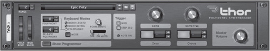
Upon first loading an instance of Thor, you’ll immediately see the Controller panel, which displays and controls Thor’s performance parameters (see Figure 8.2). Obviously, this is just an abbreviated look for Thor because it’s a very complex synth. The Controller panel is simply a way to load patches easily and begin playing with the real-time parameters, such as Portamento and Pitch.
© Propellerhead Software AB.
Because you’ve seen a few of these common parameters already in past chapters of this book, I’ll just briefly list them, as there’s no need for in-depth discussion.
![]() Patch Browser: This works exactly as in other devices.
Patch Browser: This works exactly as in other devices.
![]() Pitch Wheel: No mystery here. There is also a Range setting above, which governs the amount of pitch (+/− 2 octaves).
Pitch Wheel: No mystery here. There is also a Range setting above, which governs the amount of pitch (+/− 2 octaves).
![]() Mod Wheel: Although this is a common parameter, you’ll find that there are several sources that can be routed to this wheel, making it quite versatile.
Mod Wheel: Although this is a common parameter, you’ll find that there are several sources that can be routed to this wheel, making it quite versatile.
![]() Master Volume: This knob adjusts the overall amplitude of Thor.
Master Volume: This knob adjusts the overall amplitude of Thor.
Now let’s dig into the more complicated parameters of Thor, starting with the keyboard modes. Although most of these parameters may seem a little common, like Portamento, Thor introduces some additional features that set it apart from anything you’ve learned about up to this point.
Thor includes two kinds of polyphony, as you can see from Figure 8.2.
![]() Polyphony: This is the standard polyphony that you’ve already read about in previous chapters. Thor supports a polyphony count of 0–32 voices.
Polyphony: This is the standard polyphony that you’ve already read about in previous chapters. Thor supports a polyphony count of 0–32 voices.
![]() Release Polyphony: This is a unique type of polyphony that deals with the decay of your patches. Simply put, Release Polyphony manages the number of notes that are allowed to decay naturally after you release a note on your keyboard. It has a maximum value of 32, just like the regular polyphony. When set to its lowest value of 0, any notes played after released notes simply cut those released notes.
Release Polyphony: This is a unique type of polyphony that deals with the decay of your patches. Simply put, Release Polyphony manages the number of notes that are allowed to decay naturally after you release a note on your keyboard. It has a maximum value of 32, just like the regular polyphony. When set to its lowest value of 0, any notes played after released notes simply cut those released notes.
NOTE: Keep in mind that the greater the polyphony count, the more CPU you use.
In addition to the polyphony are the play modes, which you can select by clicking on them with your mouse or by using the Mode button. Let’s discuss them in detail.
![]() Mono Legato: This simple monophonic mode does not retrigger the envelope.
Mono Legato: This simple monophonic mode does not retrigger the envelope.
![]() Mono Retrig: This monophonic mode does exactly the opposite, triggering the envelope even if another note is already held down.
Mono Retrig: This monophonic mode does exactly the opposite, triggering the envelope even if another note is already held down.
![]() Polyphonic: When this mode is selected, Thor plays notes according to the number of polyphony and release polyphony that are assigned to it.
Polyphonic: When this mode is selected, Thor plays notes according to the number of polyphony and release polyphony that are assigned to it.
Moving to the right, the Portamento knob creates a sliding effect between played notes. The knob determines the amount of time it will take to slide from one note to another. It can be used with either monophonic or polyphonic patches and is a great tool for creating some interesting effects. There are three modes:
![]() Off: No Portamento effect.
Off: No Portamento effect.
![]() On: The Portamento effect happens no matter what notes you play on the keyboard.
On: The Portamento effect happens no matter what notes you play on the keyboard.
![]() Auto: When this mode is selected, you hear the effect only when more than one note is played. However, if the mono modes are selected, Portamento will affect the legato notes.
Auto: When this mode is selected, you hear the effect only when more than one note is played. However, if the mono modes are selected, Portamento will affect the legato notes.
The Trigger section dictates how Thor will be played:
![]() MIDI: Selecting this option tells Thor to respond only when receiving note information via MIDI.
MIDI: Selecting this option tells Thor to respond only when receiving note information via MIDI.
![]() Step Seq (Sequencer): Selecting this option tells Thor to respond when receiving note information from the Step Sequencer.
Step Seq (Sequencer): Selecting this option tells Thor to respond when receiving note information from the Step Sequencer.
![]() Both: You can select both the MIDI and Step Sequencer options to have Thor respond to either option.
Both: You can select both the MIDI and Step Sequencer options to have Thor respond to either option.
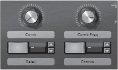
To the right of the Trigger section are the Virtual controls, which consist of two knobs and two buttons (see Figure 8.3). This is a feature unique to Thor, as these knobs and buttons can be assigned to several parameters and can also be easily automated.
Figure 8.3
© Propellerhead Software AB.
All the assignments are handled by the modulation bus, which you’ll read about later in this chapter. Note that you can easily label the different knobs and buttons simply by double-clicking on their corresponding labels and typing new names as needed.
In addition, the functions that you assign to the buttons can be assigned to MIDI notes to turn them off and on much more easily. For example, you could route them to the Delay and Chorus power switches and use MIDI notes to turn the effects off and on during a performance, thereby making the performance all the more dynamic. Just some food for thought, but I’ll show you how to do this later.
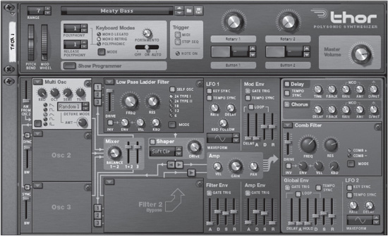
The Programmer
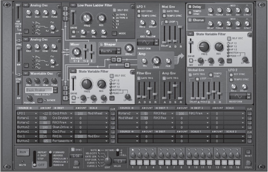
The Programmer is where the real magic of Thor comes into play because there are so many different creative possibilities (see Figure 8.4). I could spend much more time than a book allows, but I’m going to leave that part to you. First things first, let’s take a tour through this interface to better understand how everything works.
© Propellerhead Software AB.
Because this is a semimodular synth, I’m going to refer to each of these highlighted segments as modules, as that is in fact what they are. Each of these modules is routed or can be routed in a variety of different configurations to produce very different and complex sounds. To make things simple, I’m going to section off and explain each of the following modules:
![]() The oscillators
The oscillators
![]() The Mixer
The Mixer
![]() The filters
The filters
![]() The Shaper
The Shaper
![]() The Amplifier
The Amplifier
![]() The LFO
The LFO
![]() The envelopes
The envelopes
![]() The global parameters
The global parameters
TIP: Because you have already read about a lot of the principles of synthesis, such as the definitions of an oscillator and envelope, I’m going to jump straight into touring the actual functions and features here to save time and get you working in Thor quickly.
The Oscillators
Thor has a total of three slots for oscillator modules, and each allows for six types of oscillators. You can select any of these oscillators by clicking on the pop-up menu arrow at the top-left corner of each slot:
![]() Analog
Analog
![]() Wavetable
Wavetable
![]() FM Pair
FM Pair
![]() Multi Oscillator
Multi Oscillator
![]() Noise
Noise
You also have the option to select Off to bypass a slot.
Oscillators share several common parameters, so let’s get them out of the way first.
![]() Oct (Octave): The Octave knob sets the oscillator tuning to one of 10 possible octaves.
Oct (Octave): The Octave knob sets the oscillator tuning to one of 10 possible octaves.
![]() Semi: This parameter alters the pitch in semitone increments.
Semi: This parameter alters the pitch in semitone increments.
![]() Tune: This fine-tuning knob adjusts in cents.
Tune: This fine-tuning knob adjusts in cents.
![]() Kbd (Keyboard): The Keyboard knob tells Thor how to interpret the pitch of each incoming MIDI message.
Kbd (Keyboard): The Keyboard knob tells Thor how to interpret the pitch of each incoming MIDI message.
![]() Waveform selectors: Each oscillator can produce one of several different waveforms.
Waveform selectors: Each oscillator can produce one of several different waveforms.
![]() Sync: Each of the oscillator modules can be synced. More on this later.
Sync: Each of the oscillator modules can be synced. More on this later.
THE ANALOG OSCILLATOR
The Analog oscillator (Analog Osc) is the most common type of oscillator (see Figure 8.5). This module is similar in sound and style to that found in the SubTractor. There are four waveforms from which to select: Sawtooth, Pulse, Triangle, and Sine.

© Propellerhead Software AB.
You’ll also notice that there is a Pulse Width knob (labeled PW), which affects just the pulse waveform.
THE WAVETABLE OSCILLATOR
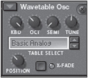
The Wavetable oscillator (Wavetable Osc) is fashioned after the classic wavetable synths of the 1980s, such as the PPG Waveterm and Waldorf Wave (see Figure 8.6). Wavetable are compilations of different waveforms combined to create much different waveforms.
© Propellerhead Software AB.
You can choose from 32 wavetables here, ranging from the simplest (Basic Analog) to the more complex (Sax) to the actual original wavetables found in the classic PPG synth. This module also includes some exclusive parameters.
![]() Position: This knob determines at which point to sweep through the selected wavetable. You’ll find that this alters the timbre of the wavetable drastically.
Position: This knob determines at which point to sweep through the selected wavetable. You’ll find that this alters the timbre of the wavetable drastically.
![]() X-Fade: The X-Fade option is used to smooth the transition between waveforms found within a wavetable.
X-Fade: The X-Fade option is used to smooth the transition between waveforms found within a wavetable.
PHASE MODULATION OSCILLATOR
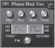
The Phase Modulation oscillator (Phase Mod Osc) is unique in that it uses different waveforms to generate harmonics (see Figure 8.7). The Phase Modulation knob (labeled “PM”) controls the amount of modulation of one waveform over a carrier sine wave. Adjusting the PM knob morphs the wave shape between a sine wave and the selected modulator wave. This is also known as phase-distortion synthesis, made popular by Casio CZ synthesizers in the mid 1980s.
© Propellerhead Software AB.
The first waveform selector includes the following:
![]() Sawtooth
Sawtooth
![]() Square
Square
![]() Pulse
Pulse
![]() Pulse and Sine
Pulse and Sine
![]() Sine and Flat
Sine and Flat
![]() Saw×Sine (combined)
Saw×Sine (combined)
![]() Sine×Sine (combined)
Sine×Sine (combined)
![]() Sine×Pulse (combined)
Sine×Pulse (combined)
The second waveform selector offers the first five waveforms.
FM PAIR OSCILLATOR
The FM Pair oscillator (FM Pair Osc; see Figure 8.8) produces a unique sound through the use of frequency modulation (FM). FM is a form of synthesis that combines a sine wave oscillator called the carrier with another sine wave oscillator called the modulator. The modulator controls the frequency of the carrier, and different complex harmonics are created by varying the pitch between the carrier and modulator.

© Propellerhead Software AB.
The pitch between the carrier and modulator are always proportionally relative, and there are 32 offset values that scale the ratio between the two sine wave sources. The FM Amount knob controls the intensity of the modulator influence over the carrier. When the FM Amount knob is set to 0, there is no FM modulation; raising this control increases the frequency modulation, resulting in more complex harmonics.
MULTI OSCILLATOR
The Multi oscillator (Multi Osc; see Figure 8.9) creates huge, wide sounds by stacking several oscillators of the same waveform type. This module has all the same waveforms as the Analog oscillator, but with additional parameters:

© Propellerhead Software AB.
![]() Amt (Amount): This knob controls the amount of detune between the multiple oscillators.
Amt (Amount): This knob controls the amount of detune between the multiple oscillators.
![]() Detune Mode: There are eight modes or starting points, where the Amount knob will intensify the detune effect. For example, there is an Octave mode, which stacks a lower and higher note an octave apart. The Amount knob can then be used to create strange but interesting detune effects.
Detune Mode: There are eight modes or starting points, where the Amount knob will intensify the detune effect. For example, there is an Octave mode, which stacks a lower and higher note an octave apart. The Amount knob can then be used to create strange but interesting detune effects.
NOISE OSCILLATOR
Thor’s Noise oscillator (Noise Osc) sounds much different from any module I’ve heard in a long time (see Figure 8.10). It offers several types of noise, most of which can then be manipulated by a modulating BW (Bandwidth) knob, to the right of the different noise waveforms. Noise is particularly useful when creating percussion sounds such as cymbals or snare drums.

© Propellerhead Software AB.
![]() Band: This oscillator produces a pure noise that can be changed to a pure tone by using the Bandwidth knob.
Band: This oscillator produces a pure noise that can be changed to a pure tone by using the Bandwidth knob.
![]() Sample and Hold (S&H): This is a random type of noise, which sounds a lot like bit crushing, where a pure signal is broken down and degraded bit by bit.
Sample and Hold (S&H): This is a random type of noise, which sounds a lot like bit crushing, where a pure signal is broken down and degraded bit by bit.
![]() Static: This is an emulation of static noise that you might hear on a car radio.
Static: This is an emulation of static noise that you might hear on a car radio.
![]() Color: This type of noise is associated with a color type based on its characteristics.
Color: This type of noise is associated with a color type based on its characteristics.
![]() White: This mode produces a pure white noise, which cannot be altered by the Bandwidth knob.
White: This mode produces a pure white noise, which cannot be altered by the Bandwidth knob.
ADDITIONAL OSCILLATOR PARAMETERS
In addition to the three oscillators, this section includes a couple of routing possibilities to help shape the overall sound.
![]() Sync buttons: These buttons will synchronize the wave cycle of oscillators 2 and 3 to oscillator 1. This forces the oscillators to restart when a new cycle begins on oscillator 1. A good way to demonstrate this is to create analog oscillators in the first and second slots. Set the Semi knob on the second oscillator to a non-zero value. If you audition this sound, you will hear a chord of two different notes, one from each oscillator. Now activate the Sync button, and oscillator 2 will sync to oscillator 1. The result sounds like a one note with rich harmonics.
Sync buttons: These buttons will synchronize the wave cycle of oscillators 2 and 3 to oscillator 1. This forces the oscillators to restart when a new cycle begins on oscillator 1. A good way to demonstrate this is to create analog oscillators in the first and second slots. Set the Semi knob on the second oscillator to a non-zero value. If you audition this sound, you will hear a chord of two different notes, one from each oscillator. Now activate the Sync button, and oscillator 2 will sync to oscillator 1. The result sounds like a one note with rich harmonics.
![]() BW slider: This slider works in combination with the Sync buttons, as they adjust the sync bandwidth. This can create much more pronounced synced sound as the value increases.
BW slider: This slider works in combination with the Sync buttons, as they adjust the sync bandwidth. This can create much more pronounced synced sound as the value increases.
![]() AM slider: This slider creates a ring-modulation effect between oscillators 1 and 2. Simply adjust the slider and then make changes to the pitch settings of either oscillator to hear the effect.
AM slider: This slider creates a ring-modulation effect between oscillators 1 and 2. Simply adjust the slider and then make changes to the pitch settings of either oscillator to hear the effect.
The Mixer
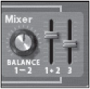
The Mixer is used to mix the outputs of the three oscillators (see Figure 8.11). It’s fairly straightforward and easy to use. There are just a couple of key features to point out here.
![]() Balance 1–2: This knob enables you to adjust the balance between oscillators 1 and 2.
Balance 1–2: This knob enables you to adjust the balance between oscillators 1 and 2.
![]() Sliders: These sliders adjust the volume of all three oscillators. The first slider adjusts the combined volume of oscillators 1 and 2. The second slider adjusts just oscillator 3.
Sliders: These sliders adjust the volume of all three oscillators. The first slider adjusts the combined volume of oscillators 1 and 2. The second slider adjusts just oscillator 3.
© Propellerhead Software AB.
The Filters
Need to do some sonic sculpting on those raw, savage oscillators? If so, you have a large assortment of semi-modular filters from which to choose. (See Figure 8.12.) You can have up to three filters running at once, although the third filter, filter 3, controls the final “mix” of the patch. Filters 1 and 2 are optional. However, should you choose to use them, you do have some options in the routing department. For example, oscillator 1 can be routed directly to filter 1, while in the same patch, oscillator 2 could be routed to filter 2! Another example would be routing filter 1 directly to filter 2. There are loads of possibilities. And, like I said, there are several filter types. (Ever filtered with a human throat before?)

© Propellerhead Software AB.
Before you learn about the different filters, it’s a good idea to first learn about their common parameters.
![]() Frequency/Resonance (Freq/Res): No filter would be complete without these vital parameters. However, these parameters are a little less obvious when discussing the Formant filter, which I’ll do later in this chapter.
Frequency/Resonance (Freq/Res): No filter would be complete without these vital parameters. However, these parameters are a little less obvious when discussing the Formant filter, which I’ll do later in this chapter.
![]() Keyboard Tracking (Kbd): This knob determines how the filter frequency reacts to notes played on your keyboard.
Keyboard Tracking (Kbd): This knob determines how the filter frequency reacts to notes played on your keyboard.
![]() Envelope (Env): This knob determines how the filter frequency reacts to the Filter Envelope.
Envelope (Env): This knob determines how the filter frequency reacts to the Filter Envelope.
![]() Velocity (Vel): This knob determines how the filter frequency reacts to velocity.
Velocity (Vel): This knob determines how the filter frequency reacts to velocity.
![]() Invert (Inv): This button inverts how the filter frequency reacts to the filter envelope.
Invert (Inv): This button inverts how the filter frequency reacts to the filter envelope.
![]() Drive: Each filter includes an input gain, which can be used to overdrive the filter effect. Note that the drive reacts differently with the Low Pass Ladder filter.
Drive: Each filter includes an input gain, which can be used to overdrive the filter effect. Note that the drive reacts differently with the Low Pass Ladder filter.
NOTE: Looking back at Figure 8.12, you’ll notice the 1, 2, and 3 buttons to the immediate left of the primary filters. These buttons are used to assign three oscillators to one or both of the available filter modules. Simply click on them to activate them, load a filter, and you’re good to go. Just make sure that you click on the Filter 2 to Amplifier button to route filter 2 to the Amplifier; otherwise, you won’t hear it.
LOW PASS LADDER FILTER
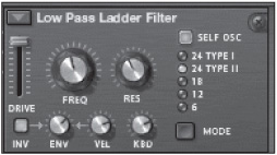
The Low Pass Ladder filter is fashioned after classic filter modules commonly found on Moog modular synths (see Figure 8.13). There are five filter modes in addition to a built-in shaper, which reshapes the waveform with distortion.
© Propellerhead Software AB.
The Self Oscillation (Self Osc) button at the top-right corner is used to create a feedback loop of high-pitched, bell-like tones that can be further enhanced by making use of the built-in saturation shaper and the 24 dB slopes. A word of warning, though: A self-oscillating filter can get very loud and easily clip your mix, not to mention damage your hearing.
TIP: You can use the Keyboard (Kbd) knob to control the pitch to the self-oscillating filter. Just turn it up to its maximum value, and it will produce 12 semitones per octave.
There are two types of 24 dB slopes, and each processes the saturation effect differently. Type I places saturation after the filter going into the feedback loop so that only the resonant signal is shaped. Type II places the saturation at the input of the filter so that both the incoming signal and the feedback loop are shaped.
STATE VARIABLE FILTER
The State Variable filter differs greatly from the Low Pass Ladder filter because it offers filtering possibilities other than just the lower frequencies (see Figure 8.14). Instead, the State Variable filter includes Band Pass mode, High Pass mode, as well as a unique Notch/Peak mode that combines a low-pass and high-pass filter. The filter frequency is then routed to the LP/HP knob that mixes between the two filters. This description sounds a little complicated, I know, but with a little practice, you will quickly find ways to include this filter in your Thor patches.

© Propellerhead Software AB.
COMB FILTER
The Comb filter is a bit simpler than the previous two filters that you’ve looked at (see Figure 8.15). As you will recall from Chapter 7, “The Malström: Close-Up,” a comb filter is essentially a series of delays with very short delay times assigned to each delay instance, resulting in a detuned sound. The feedback of these delays is controlled by the Resonance parameter in each filter. The difference between the Comb+ and Comb− filter is the polarity of the feedback into the delay.

© Propellerhead Software AB.
FORMANT FILTER
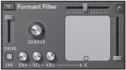
The Formant filter is probably one of the coolest modules I’ve used in Reason (see Figure 8.16). It’s not your traditional filter module; its primary function is to produce vowel sounds by making use of the XY pad to emulate the vowels through filter formant. Aside from the traditional parameters in the Formant filter, the Gender knob offers the ability to alter the timbre of the filter to emulate a male voice or a female voice. Note that the Envelope (Env), Velocity (Vel), and Keyboard (Kbd) knobs affect or offset only the X slider (horizontal).
© Propellerhead Software AB.
TIP: There are quite a few “choir” patches available in Thor, but one of the best examples of the Formant filter has to be the I Am Thor patch, which is one of the default patches when an instance of Thor is created.
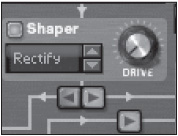
The Shaper
The Shaper is Thor’s onboard distortion (see Figure 8.17). Its primary function is to alter the waveshape of the oscillators by adding a bit of saturation or a heavy digital distortion. It’s split up into three parameters:
© Propellerhead Software AB.
![]() On/Off: This turns the Shaper on and off.
On/Off: This turns the Shaper on and off.
![]() Modes: There are nine modes of waveshaping, including Soft/Hard Clip, Saturate, Sine, Unipulse, Peak, Rectify, and Wrap.
Modes: There are nine modes of waveshaping, including Soft/Hard Clip, Saturate, Sine, Unipulse, Peak, Rectify, and Wrap.
![]() Drive: This adjusts the amount of waveshaping.
Drive: This adjusts the amount of waveshaping.
NOTE: Looking back at Figure 8.17, you can see two buttons below the Shaper—one pointing to the left and one to the right. These buttons determine how the Shaper is routed through Thor. Activating the button that points to the left sends the Shaper output to filter 2. Clicking on the button that points to the right sends the output of the Shaper to the Amplifier.
The Amplifier
After you have mixed, filtered, and shaped your oscillators, you’re ready to move on to the Amplifier. There are three main parameters to be aware of here.
![]() Gain: This adjusts the overall volume.
Gain: This adjusts the overall volume.
![]() Velocity (Vel): This determines how much velocity affects the gain.
Velocity (Vel): This determines how much velocity affects the gain.
![]() Pan: This places the oscillators in the stereo field.
Pan: This places the oscillators in the stereo field.
The LFO
The LFO is used to modulate the oscillators by introducing the waveform of another inaudible oscillator operating at a very low frequency. Additionally, this is a polyphonic LFO, which means that every note played will have its own LFO effect. The LFO can generate 18 waveforms from its spin controls that can be applied by making use of the following parameters:
![]() Rate: This sets the speed of the LFO in hertz (Hz). Note that if Tempo Sync is selected, the Rate knob will adjust in note values.
Rate: This sets the speed of the LFO in hertz (Hz). Note that if Tempo Sync is selected, the Rate knob will adjust in note values.
![]() Delay: This introduces a delay prior to the LFO effect.
Delay: This introduces a delay prior to the LFO effect.
![]() Keyboard (Kbd) Follow: This sets how much the rate is controlled by the notes played on the keyboard.
Keyboard (Kbd) Follow: This sets how much the rate is controlled by the notes played on the keyboard.
![]() Key Sync: This resets the LFO each time a note is played.
Key Sync: This resets the LFO each time a note is played.
TIP: Thor actually includes two LFOs, the second of which is included with the global parameters.
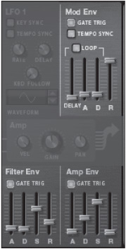
The Envelopes
Thor includes three envelopes that all perform different tasks for your patches (see Figure 8.18). All of them include the standard ADSR parameters (Attack, Decay, Sustain, Release), but they also include a few extra bells and whistles. Let’s cover each one.
THE FILTER/AMP ENVELOPES
The Filter/Amp envelopes are used to alter the character of Thor’s filter and amplifier over a determined period of time. Aside from the standard parameters, they both include a Gate Trig parameter. On the surface, this parameter is meant to be used as a power button of sorts because it activates the envelopes. But the Gate Trig parameter can also be accessed by way of the modulation bus, which you’ll read about later in this chapter.
© Propellerhead Software AB.
THE MOD ENVELOPE
The Mod envelope functions a bit differently from the others. For one, the Mod envelope does not have a default assignment. That has to be handled by the modulation bus. It also has a different type of envelope (Attack, Decay, Release, no Sustain), and it includes additional parameters:
![]() Delay: This introduces a delay before the envelope takes effect. The range is 0 ms to 10.3 seconds.
Delay: This introduces a delay before the envelope takes effect. The range is 0 ms to 10.3 seconds.
![]() Loop: This loops the envelope as long as a note is held on your keyboard.
Loop: This loops the envelope as long as a note is held on your keyboard.
![]() Tempo Sync: When activated, this button syncs up all the Mod envelope parameters to the tempo of the song. Each parameter is adjustable in note values.
Tempo Sync: When activated, this button syncs up all the Mod envelope parameters to the tempo of the song. Each parameter is adjustable in note values.
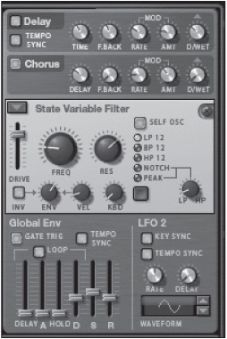
The Global Parameters
Thor’s global parameters affect the entire synth by introducing effects, filters, and a second LFO (see Figure 8.19). Let’s go ahead and burn through these modules.
© Propellerhead Software AB.
THE EFFECTS
In addition to the Shaper, which you looked at earlier in this chapter, Thor includes Delay and Chorus effects to give your patches a little extra zing. You can read much more about these types of effects in Chapter 10, “Effects: Close-Up.” You learned what a delay is, back in Chapter 2, “Recording,” when we talked about The Echo. Thor has a very similar “Mini Echo,” if you will. Chorus is a very cool effect that modulates an incoming signal slightly in and out of pitch. The result is a fattening effect that really bulks up your patches.
The Delay parameters include the following:
![]() Time: This adjusts the amount of time between delay repeats.
Time: This adjusts the amount of time between delay repeats.
![]() Feedback: This determines the number of delay repeats.
Feedback: This determines the number of delay repeats.
![]() Rate: This determines the rate at which the delay time is modulated.
Rate: This determines the rate at which the delay time is modulated.
![]() Amount (Amt): This determines how intense the modulation is.
Amount (Amt): This determines how intense the modulation is.
![]() Dry/Wet: This adjusts the amount between the unprocessed (dry) and processed (wet) signal. In this case, if the signal is completely wet, you hear only the delay repeats.
Dry/Wet: This adjusts the amount between the unprocessed (dry) and processed (wet) signal. In this case, if the signal is completely wet, you hear only the delay repeats.
The Chorus parameters include the following:
![]() Delay: This is similar to the Time knob in the Delay. However, because this is a Chorus effect, the Delay parameter introduces a very short time in the effect.
Delay: This is similar to the Time knob in the Delay. However, because this is a Chorus effect, the Delay parameter introduces a very short time in the effect.
![]() Feedback: This determines the number of delay repeats (same as with the Delay effect).
Feedback: This determines the number of delay repeats (same as with the Delay effect).
![]() Rate: This determines the rate at which the delay time is modulated (same as with the Delay effect).
Rate: This determines the rate at which the delay time is modulated (same as with the Delay effect).
![]() Amount (Amt): This determines how intense the modulation is (same as with the Delay effect).
Amount (Amt): This determines how intense the modulation is (same as with the Delay effect).
![]() Dry/Wet: This adjusts the amount between the unprocessed (dry) and processed (wet) signal.
Dry/Wet: This adjusts the amount between the unprocessed (dry) and processed (wet) signal.
THE FILTER
The third Filter module available in Thor affects the entire synth rather than just the oscillators. Because I have already discussed the different filters available, I won’t repeat myself here. The best advice I can give is to try the different filter types to see which one fits your patch. Note that this is the only filter in Thor that does not require a note to trigger it. This capability is useful when you’re using the filter to process external audio or to create a sine wave using self-oscillation.
THE GLOBAL ENVELOPE
The Global envelope is a bit more complicated than the others previously discussed because it includes more parameters and must be assigned via the modulation bus. Aside from the standard ADSR parameters, the Global envelope includes the following:
![]() Delay: This determines the delay time before the envelope kicks in.
Delay: This determines the delay time before the envelope kicks in.
![]() Loop: Activating this causes the envelope to loop once triggered.
Loop: Activating this causes the envelope to loop once triggered.
![]() Hold: This creates a hold before the Decay parameter begins.
Hold: This creates a hold before the Decay parameter begins.
![]() Tempo Sync: This sets the parameters of the envelope to the tempo of your song.
Tempo Sync: This sets the parameters of the envelope to the tempo of your song.
![]() Gate Trigger: This activates the Global envelope.
Gate Trigger: This activates the Global envelope.
LFO 2
LFO 2 is much like the one you toured earlier in this chapter, as it has most of the same parameters (sans the Kbd Follow). However, unlike LFO 1, this LFO is not polyphonic. Also, it must be assigned to a parameter via the modulation bus, which you’ll learn about next.
The Modulation Bus
Once you have crafted your Thor patch using its many oscillators, filters, and effects, you’ll want to take your patches to the next level, which is handled by the modulation bus (see Figure 8.20). Here, you can add enhancements and modifications to your patch to make them ideal for live performance, or just to make them sound more creative and spontaneous in your sequences.

© Propellerhead Software AB.
Before I get in depth with the modulation bus, let’s first consider its main parameters:
![]() Source: Sources can be pretty much anything you want them to be inside Thor. Click on the first source of any modulation bus, and you’ll find that everything from audio inputs to LFOs to oscillators can be used as modulation sources.
Source: Sources can be pretty much anything you want them to be inside Thor. Click on the first source of any modulation bus, and you’ll find that everything from audio inputs to LFOs to oscillators can be used as modulation sources.
![]() Destination: Once a source has been selected, you must select what that source is going to modulate, which is the destination.
Destination: Once a source has been selected, you must select what that source is going to modulate, which is the destination.
All destinations have an Amount slider that determines the intensity and direction of modulation for the destination.
![]() Scale: The Scale parameter is used to govern the modulation amount. For example, say you set up a simple modulation where the source (LFO 1) is routed to the destination (Osc1 Pitch). If you play a note, you’ll hear LFO 1 modulate Osc 1, which will create a pitch-based vibrato. You’ll probably not want to hear the note played that way all the time, so you can assign the modulation to an additional parameter that will control or scale the effect, such as a modulation wheel. Once you have selected this parameter, you can then use its Amount slider to determine the intensity and direction of the scale effect.
Scale: The Scale parameter is used to govern the modulation amount. For example, say you set up a simple modulation where the source (LFO 1) is routed to the destination (Osc1 Pitch). If you play a note, you’ll hear LFO 1 modulate Osc 1, which will create a pitch-based vibrato. You’ll probably not want to hear the note played that way all the time, so you can assign the modulation to an additional parameter that will control or scale the effect, such as a modulation wheel. Once you have selected this parameter, you can then use its Amount slider to determine the intensity and direction of the scale effect.
This information is a lot to take in at one time, but I have created a couple of examples for you to help make more sense out of it. Keep in mind that there are 13 modulation buses. While there is no tooltip to reference them, internally they are numbered from 1 to 13 starting from the top of the left column and going down, then from the top of the right column and going down. There are three types of modulation buses:
![]() Modulation buses 1–7 are Source→Destination→Scale buses.
Modulation buses 1–7 are Source→Destination→Scale buses.
![]() Modulation buses 8–11 are Source→Destination 1→Destination 2→Scale buses.
Modulation buses 8–11 are Source→Destination 1→Destination 2→Scale buses.
![]() Modulation buses 12–13 are Source→Destination→Scale 1→Scale 2 buses.
Modulation buses 12–13 are Source→Destination→Scale 1→Scale 2 buses.
TIP: To the immediate right of every modulation bus is a Clear (Clr) button. Click this button to reset the bus.
Modulation Sources
At this point, it would be a good idea to list all the possible modulation sources for the Voice section (oscillators, envelopes, LFO, filter 1/2, and the Shaper), as well as the Global section (envelope, filter 3, LFO 2, and so on). Notice the small downward-pointing triangle icons on each routing slot. (This icon always indicates a pop-up menu is available.) Click on the triangle icon or anywhere to the left in the source field to access the Modulation Source pop-up menu (see Figure 8.21).

© Propellerhead Software AB.
![]() Voice Key: This assigns modulation according to notes and is divided into four possible parameters: Note (Full Range), Note 2 (Octave), Velocity, and Gate.
Voice Key: This assigns modulation according to notes and is divided into four possible parameters: Note (Full Range), Note 2 (Octave), Velocity, and Gate.
![]() Osc 1/2/3: This assigns any of Thor’s oscillators as a modulation source.
Osc 1/2/3: This assigns any of Thor’s oscillators as a modulation source.
![]() Filter 1/2: This assigns the audio output of filter 1 or 2 as modulation sources.
Filter 1/2: This assigns the audio output of filter 1 or 2 as modulation sources.
![]() Shaper: This assigns the audio output of the Shaper as a modulation source.
Shaper: This assigns the audio output of the Shaper as a modulation source.
![]() Amp: This assigns the audio output of the Amplifier as a modulation source.
Amp: This assigns the audio output of the Amplifier as a modulation source.
![]() LFO 1: This assigns LFO as a modulation source. It’s perfect for creating a vibrato or tremolo effect.
LFO 1: This assigns LFO as a modulation source. It’s perfect for creating a vibrato or tremolo effect.
![]() Filter/Amp/Mod Env: This assigns either of these envelopes as a modulation source.
Filter/Amp/Mod Env: This assigns either of these envelopes as a modulation source.
And now, on to the global modulation parameters:
![]() Global Env: This assigns the global envelope as the modulation source.
Global Env: This assigns the global envelope as the modulation source.
![]() Voice Mixer: This assigns the left and right mixer inputs as modulation sources.
Voice Mixer: This assigns the left and right mixer inputs as modulation sources.
![]() Last Key: This applies modulation based on the last monophonic note played, either via the built-in step sequencer or MIDI. You can select Note, Velocity, or Gate to be your source of modulation.
Last Key: This applies modulation based on the last monophonic note played, either via the built-in step sequencer or MIDI. You can select Note, Velocity, or Gate to be your source of modulation.
![]() MIDI Key: This behaves similarly to Last Key, but this modulation is heard on notes globally. As with Last Key, you have a choice of Note, Velocity, or Gate.
MIDI Key: This behaves similarly to Last Key, but this modulation is heard on notes globally. As with Last Key, you have a choice of Note, Velocity, or Gate.
![]() LFO 2: This assigns LFO 2 as a modulation source.
LFO 2: This assigns LFO 2 as a modulation source.
![]() Performance: This assigns performance parameters (Mod Wheel/Pitch Wheel, Breath, After Touch, and Expression) as modulation sources.
Performance: This assigns performance parameters (Mod Wheel/Pitch Wheel, Breath, After Touch, and Expression) as modulation sources.
![]() Modifiers: This assigns the rotary knobs and buttons as modulation sources.
Modifiers: This assigns the rotary knobs and buttons as modulation sources.
![]() Sustain Pedal: This assigns a sustain pedal to be your modulation source. If you don’t have one yet, go to your local music shop and pick one up. It’s worth the cost.
Sustain Pedal: This assigns a sustain pedal to be your modulation source. If you don’t have one yet, go to your local music shop and pick one up. It’s worth the cost.
![]() Polyphony: This sets polyphony as a modulation source. You can use it to create different envelope attacks depending on how many notes you play at one time.
Polyphony: This sets polyphony as a modulation source. You can use it to create different envelope attacks depending on how many notes you play at one time.
![]() Step Sequencer: This assigns one of eight parameters (Gate, Note, Curve 1/2, Gate Length, Step Duration, and Start/End Trig) as a modulation source.
Step Sequencer: This assigns one of eight parameters (Gate, Note, Curve 1/2, Gate Length, Step Duration, and Start/End Trig) as a modulation source.
![]() CV Inputs 1–4: This allows you to use other Reason devices (Matrix, Redrum, Dr. Octo Rex) as modulation sources via any or all of the CV inputs in Thor’s rear panel.
CV Inputs 1–4: This allows you to use other Reason devices (Matrix, Redrum, Dr. Octo Rex) as modulation sources via any or all of the CV inputs in Thor’s rear panel.
![]() Audio Inputs 1–4: This allows you to use the audio outputs of other Reason devices as modulation sources.
Audio Inputs 1–4: This allows you to use the audio outputs of other Reason devices as modulation sources.
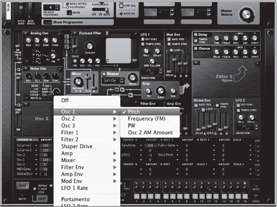
Modulation Destinations
As you can imagine, there are also quite a few modulation destinations (see Figure 8.22).
© Propellerhead Software AB.
![]() Osc 1: This assigns the parameters of Osc 1 (Pitch, Frequency, Pulse Width, and Osc 2 AM Amount) as modulation destinations.
Osc 1: This assigns the parameters of Osc 1 (Pitch, Frequency, Pulse Width, and Osc 2 AM Amount) as modulation destinations.
![]() Osc 2/3: These are the same as Osc 1 without the AM option.
Osc 2/3: These are the same as Osc 1 without the AM option.
![]() Filter 1/2: This assigns the parameters of either filter 1 or filter 2 (Audio Input, Frequency, Frequency [FM], Res, Drive, Gender, LP/HP Mix) as modulation destinations.
Filter 1/2: This assigns the parameters of either filter 1 or filter 2 (Audio Input, Frequency, Frequency [FM], Res, Drive, Gender, LP/HP Mix) as modulation destinations.
![]() Shaper Drive: This assigns the Shaper drive as a modulation destination.
Shaper Drive: This assigns the Shaper drive as a modulation destination.
![]() Amp: This assigns the velocity, pan, and input of the Amplifier as modulation destinations.
Amp: This assigns the velocity, pan, and input of the Amplifier as modulation destinations.
![]() Mixer: This assigns the parameters of the Mix section (Osc 1+2 Level/Balance, Osc 3 Level) as modulation destinations.
Mixer: This assigns the parameters of the Mix section (Osc 1+2 Level/Balance, Osc 3 Level) as modulation destinations.
![]() Filter/Amp/Mod Env: These assign the parameters of either envelope as modulation destinations.
Filter/Amp/Mod Env: These assign the parameters of either envelope as modulation destinations.
![]() LFO 1 Rate: This assigns the LFO 1 Rate as a modulation destination.
LFO 1 Rate: This assigns the LFO 1 Rate as a modulation destination.
And here are the global destinations:
![]() Portamento: This sets the Portamento time as a modulation destination.
Portamento: This sets the Portamento time as a modulation destination.
![]() LFO 2 Rate: This sets the rate of LFO 2 as a modulation destination.
LFO 2 Rate: This sets the rate of LFO 2 as a modulation destination.
![]() Global Envelope: This assigns any of the Global envelope parameters as a modulation destination.
Global Envelope: This assigns any of the Global envelope parameters as a modulation destination.
![]() Filter 3: This assigns several filter 3 parameters (Left/Right Inputs, Freq, Freq [FM], Resonance) as modulation destinations.
Filter 3: This assigns several filter 3 parameters (Left/Right Inputs, Freq, Freq [FM], Resonance) as modulation destinations.
![]() Chorus: This assigns almost any of the Chorus parameters (Dry/Wet, Delay, ModRate, Mod Amount, Feedback) as modulation destinations.
Chorus: This assigns almost any of the Chorus parameters (Dry/Wet, Delay, ModRate, Mod Amount, Feedback) as modulation destinations.
![]() Delay: This assigns almost any of the Delay parameters (Dry/Wet, Time, Mod Rate, Mod Amount, and Feedback) as modulation destinations.
Delay: This assigns almost any of the Delay parameters (Dry/Wet, Time, Mod Rate, Mod Amount, and Feedback) as modulation destinations.
![]() Step Sequencer: This assigns any of five Step Sequencer parameters (Trig, Rate, Transpose, Velocity, and Gate Length) as modulation destinations.
Step Sequencer: This assigns any of five Step Sequencer parameters (Trig, Rate, Transpose, Velocity, and Gate Length) as modulation destinations.
![]() CV Outputs 1–4: These set any of the four CV outputs as destinations.
CV Outputs 1–4: These set any of the four CV outputs as destinations.
![]() Audio Outputs 1–4: These assign any of the four audio outputs as destinations.
Audio Outputs 1–4: These assign any of the four audio outputs as destinations.
Some Modulation Examples
Now that you have a good idea of how the modulation bus works, let’s put that knowledge to the test by going through a few modulation exercises. Remember, adjusting modulation takes a bit of practice, so these exercises are pretty basic.
This first example illustrates a well-known effect, which is to have the modulation wheel open and close a filter. Be sure to initialize your patch before beginning by opening the Edit menu and choosing Initialize Patch.
1. In the Filter 1 slot, load the Formant filter.
2. In the modulation bus, navigate to modulation bus 1, in the upper-left corner. Click on the source field to access the pop-up menu, select Performance, and choose ModWheel as your source.
3. Assign an amount of 100.
4. Now select your destination by clicking on the destination field, selecting Filter 1, and choosing Y.
Play a note and try out the modulation wheel. The Formant filter responds by creating a vowel sound that opens and closes. You can also try assigning an amount of −100 to get the exact opposite effect.
In the next example, you create a tremolo effect and use the Rotary knob to control the effect. You can continue using the same patch from the previous example.
1. On modulation bus 2, select LFO 1 as your source.
2. Set the modulation amount to 100.
3. Open the Destination field drop-down menu, select Amp, and choose Gain as your destination.
At this point, you should now be able to clearly hear the effect. You can enhance this effect by using different waveforms in LFO 1 and changing the rate amount.
Now, let’s make it a bit more of a performance effect by routing it to the Rotary 1 knob.
1. On modulation bus 2, Set the scale amount to 100.
2. Click on the modulation bus 2 Scale field to open the pop-up menu, choose Modifiers, and select Rotary 1.
Play a note and use the first rotary knob in the Thor Play parameters. This now controls the tremolo effect.
The Step Sequencer
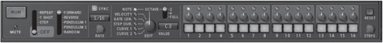
As a synth, Thor is one commanding creation of software. And as if it couldn’t get better, Thor’s Step Sequencer offers a selection of powerful features and musical creativity that you can use as a source of either melodies or modulation (see Figure 8.23). Up to 16 steps in total can be sequenced with a variety of data, including note, velocity, and gate. All in all, this thing really packs a punch.
© Propellerhead Software AB.
TIP: If you’ve been reading this book from cover to cover, this is certainly not the first time you’ve seen a step sequencer. Redrum has a first-rate sequencer of its own, as does the Matrix. However, you’ll find that the Thor Step Sequencer includes a few more tricks up its sleeves than either of the aforementioned sequencers, so read on carefully.
The Basics
Before you can get to sequencing Thor, you should probably take a couple of minutes to familiarize yourself with the basic layout of the Step Sequencer to better understand it.
![]() Run: This button is used to start and stop the Step Sequencer.
Run: This button is used to start and stop the Step Sequencer.
![]() Mute: This LED lights up whenever Thor is muted in the sequencer. However, the LED does not light up if Thor is muted from the Mixer.
Mute: This LED lights up whenever Thor is muted in the sequencer. However, the LED does not light up if Thor is muted from the Mixer.
Next up are the Run modes:
![]() Off: The sequencer does not play.
Off: The sequencer does not play.
![]() Step: The sequence advances one step at a time each time the Run button is clicked.
Step: The sequence advances one step at a time each time the Run button is clicked.
![]() One Shot: The sequence plays through one time and then stops.
One Shot: The sequence plays through one time and then stops.
![]() Repeat: The sequence plays continuously until the Run button is clicked again.
Repeat: The sequence plays continuously until the Run button is clicked again.
After selecting a Run mode, you can select one of five sequence directions:
![]() Forward: The sequence simply plays from left to right and then jumps back to the left.
Forward: The sequence simply plays from left to right and then jumps back to the left.
![]() Reverse: The sequence does exactly the opposite by playing from right to left and then jumping back to the right.
Reverse: The sequence does exactly the opposite by playing from right to left and then jumping back to the right.
![]() Pendulum 1: This plays the sequence from left to right, repeats the last step, and then plays right to left. It then repeats the first step and starts over again.
Pendulum 1: This plays the sequence from left to right, repeats the last step, and then plays right to left. It then repeats the first step and starts over again.
![]() Pendulum 2: This plays the sequence from left to right and then right to left continuously.
Pendulum 2: This plays the sequence from left to right and then right to left continuously.
![]() Random: This direction plays the sequence steps in random order.
Random: This direction plays the sequence steps in random order.
Now let’s move on to the right. The Rate setting controls the speed of the Step Sequencer. This can be set to either hertz or note values (if the Sync button is activated). You can change the value of this setting by clicking and dragging up or down on the knob.
As mentioned, up to 16 steps can be filled to the brim with sequencing data, and that data is determined by the Edit controls. These are just to the left of the sequencer steps. Note that as you select these controls and assign values to them in the sequence (by using the knobs of each step), the Value readout displays either the numeric or note value (either length or number) of each step.
![]() Note: This allows you to enter note data on a step-by-step basis. An additional switch to the right of this parameter governs the note range of the sequence. You can select two octaves, four octaves, or full range.
Note: This allows you to enter note data on a step-by-step basis. An additional switch to the right of this parameter governs the note range of the sequence. You can select two octaves, four octaves, or full range.
![]() Velocity: This sets the velocity of each sequenced step.
Velocity: This sets the velocity of each sequenced step.
![]() Gate Length: This sets the length of each sequenced step.
Gate Length: This sets the length of each sequenced step.
![]() Step Duration: This sets the length of each step in the sequence. For example, the first step can be a 1/4 note, the next can be an 1/8 note; the possibilities are endless.
Step Duration: This sets the length of each step in the sequence. For example, the first step can be a 1/4 note, the next can be an 1/8 note; the possibilities are endless.
![]() Curve 1/2: These set the value of curve data on a step-by-step basis. As mentioned, these curves are assigned through the modulation bus.
Curve 1/2: These set the value of curve data on a step-by-step basis. As mentioned, these curves are assigned through the modulation bus.
Write a Quick Sequence
Now, it’s time to put your new knowledge to the test and write in a quick first sequence.
1. Start by selecting a Thor patch that would work well for sequencing, such as a bass or lead patch.
2. Turn off a few sequencer steps to create an interesting rhythm. Try turning off steps 2, 7, 11, and 15 (see Figure 8.24).
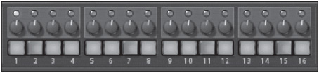
© Propellerhead Software AB.
Click the Run button to hear the sequence. Keep in mind that you’ll want to set the Play mode to Repeat. At this point, it would be a good idea to enter some notes into the sequence. Try the following notes.
![]() Step 1: C#2
Step 1: C#2
![]() Step 3: C4
Step 3: C4
![]() Step 4: C3
Step 4: C3
![]() Step 5: G4
Step 5: G4
![]() Step 6: C5
Step 6: C5
![]() Step 8: C3
Step 8: C3
![]() Step 9: C3
Step 9: C3
![]() Step 10: C3
Step 10: C3
![]() Step 12: C#4
Step 12: C#4
![]() Step 13: F4
Step 13: F4
![]() Step 14: D#2
Step 14: D#2
![]() Step 16: D#2
Step 16: D#2
TIP: If you listen to your sequence and you want to start over, you can simply click the Reset button at the far right of the Step Sequencer. Just note that clicking this button resets everything (note value, gate length, curve date, and so on), so proceed with caution.
You’ve written out a pretty interesting melodic line, so from this point on, you should try to spice it up a bit by making use of the additional Edit parameters. For example, you could select Gate Length and write in a more interesting gate pattern that makes use of staccato note lengths versus legato. You could also try altering the velocity of different notes to create a dynamic impact. The sky’s the limit really, so let your hair down and experiment.
CV/Audio Connections
Press the Tab key to flip the Rack screen around, and you’ll see that Thor has many connections that can be used to sequence with the Matrix or RPG-8, modulate other devices, or be modulated by other devices (see Figure 8.25). In addition, Thor includes several audio I/Os for pushing the creative limits of soft synthesis.
TIP: Take a quick look at the back of the Thor interface, and you’ll notice that the programmers have provided a neat cheat sheet of sorts. It lists several modulation and routing possibilities. This can be a real helper when you are just starting down the road of modular synthesis.
Audio Outputs
The audio output connections are used to output the signal from Thor to the Reason mixer. There are a couple of options:
![]() Mono/Left (1) and Right (2): These are the main outputs of Thor. Note that if you build a mono patch with Thor, use output 1 to retain the proper effect.
Mono/Left (1) and Right (2): These are the main outputs of Thor. Note that if you build a mono patch with Thor, use output 1 to retain the proper effect.
![]() Audio Outputs 3/4: These are the additional audio outputs, which can be assigned from the modulation bus.
Audio Outputs 3/4: These are the additional audio outputs, which can be assigned from the modulation bus.
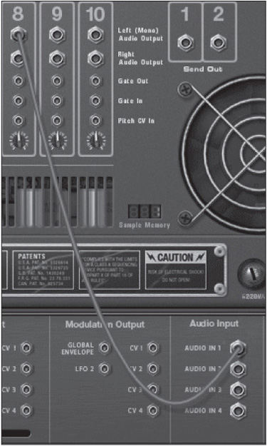
Audio Input
As you learned in the previous chapter, audio inputs on a soft synth are hot, and Thor has four of them. You can literally route just about any Reason device output to these inputs and then assign them to Thor’s various modulation inputs via the modulation bus.

© Propellerhead Software AB.
Let’s try an interesting experiment:
1. Create a new Reason song.
2. Create instances of Thor and Redrum.
3. Select the Percutron patch for Thor. This is a percussion pitch-based patch that makes use of the Step Sequencer.
4. In the Redrum sequencer, write a hi-hat pattern that has lots of dynamics.
5. Press the Tab key to flip the interface.
6. Disconnect the outputs of Redrum and connect Redrum’s hi-hat output to Thor’s Audio In 1 (see Figure 8.26).
7. Press the Tab key to flip the interface again.
8. Use Thor’s modulation bus to route Audio In 1 as the source to oscillator 1’s Pitch or FM amount (see Figure 8.27). Note that this will require you to clear a Modulation slot, as the Percutron patch uses all available slots.
At this point, you can run the step sequencers of both Reason devices, and you should now hear the hi-hat pattern modulating the pitch or FM of oscillator 1 of Thor.
Modulation Input/Output
Moving to the left, you’ll see that Thor offers a lot of possible CV I/O connections for modulation (see Figure 8.28). This can lead to some serious modulating bliss if you play your cards right. For example, you could use LFO 2 to modulate in sync with the CV input of another Reason device—for example, the Damage Control CV input of Scream 4, which would cause the amount of distortion to rise and fall in time with the tempo of your song. Or, you could also use the LFO CV output of Dr. Octo Rex to modulate the filter 1 frequency 1 CV input of Thor. And the list goes on and on and on.
© Propellerhead Software AB.
© Propellerhead Software AB.

© Propellerhead Software AB.
Let’s start with the modulation outputs:
![]() Global Envelope: This connection routes the output of the Thor Global envelope to any CV input.
Global Envelope: This connection routes the output of the Thor Global envelope to any CV input.
![]() LFO 2: This connection routes the output of LFO 2 to any CV input.
LFO 2: This connection routes the output of LFO 2 to any CV input.
![]() CV 1–4: These modulation outputs are assignable through the modulation bus and can route the CV output of just about any
CV 1–4: These modulation outputs are assignable through the modulation bus and can route the CV output of just about any
Thor parameter to the CV input of your choosing.
And now, the modulation inputs. Note that these have Amount knobs that intensify or decrease the effect.
![]() Rotary 1/2: These modulation inputs are used to route the CV outputs of any Reason device to the Rotary knobs on the front of the Thor interface. Remember that these knobs can be assigned to just about any Thor parameter.
Rotary 1/2: These modulation inputs are used to route the CV outputs of any Reason device to the Rotary knobs on the front of the Thor interface. Remember that these knobs can be assigned to just about any Thor parameter.
![]() Filter 1 Frequency: This modulation input controls the Filter Frequency knob of filter 1.
Filter 1 Frequency: This modulation input controls the Filter Frequency knob of filter 1.
![]() Amp Level: The modulation input alters the Amp envelope on the front of the Thor interface.
Amp Level: The modulation input alters the Amp envelope on the front of the Thor interface.
![]() CV 1–4: These inputs allow you to send modulation data to just about any Thor parameter via the modulation bus.
CV 1–4: These inputs allow you to send modulation data to just about any Thor parameter via the modulation bus.
NOTE: Keeping in line with the other Reason synths that you’ve already read about, Thor also includes a pair of CV inputs for the Modulation Wheel and Pitch Wheel parameters. Additionally, there are Sequencer Control inputs for the gate and CV, which are used to link up to an instance of the Matrix sequencer.
Step Sequencer CV Inputs/Outputs
Scroll down to the bottom of the Thor interface, and you’ll see that the Step Sequencer also has its own set of CV inputs and outputs (see Figure 8.29). Every parameter that you alter in a Thor sequence (Note, Gate, Velocity, and so on) can be used as a CV output. Conversely, you can use the CV outputs of other Reason devices, such as the Matrix sequencer, to control most of the vital inputs of the Thor sequencer.

© Propellerhead Software AB.
![]() Gate In (Trig): This CV input triggers the gate input of the Step Sequencer. A good way to check this out is to route the slice gate output of Dr. Octo Rex to this input. Load up a REX file and let the fun begin.
Gate In (Trig): This CV input triggers the gate input of the Step Sequencer. A good way to check this out is to route the slice gate output of Dr. Octo Rex to this input. Load up a REX file and let the fun begin.
![]() Rate In: This CV input controls the rate of the Step Sequencer. Try connecting the curve CV output of the Matrix sequencer to this.
Rate In: This CV input controls the rate of the Step Sequencer. Try connecting the curve CV output of the Matrix sequencer to this.
![]() Pitch In (Transpose): This input alters the pitch of the Step Sequencer. Try connecting the LFO output of any other Reason device to this input.
Pitch In (Transpose): This input alters the pitch of the Step Sequencer. Try connecting the LFO output of any other Reason device to this input.
![]() Gate Length In: This input alters the gate, or note length, of the sequencer steps.
Gate Length In: This input alters the gate, or note length, of the sequencer steps.
![]() Velocity In: This input alters the velocity of the sequencer steps. Both this and the gate length inputs are perfect for the Matrix or perhaps Redrum.
Velocity In: This input alters the velocity of the sequencer steps. Both this and the gate length inputs are perfect for the Matrix or perhaps Redrum.
And now, let’s look at the outputs:
![]() Note: This outputs the note data from the Step Sequencer to any device.
Note: This outputs the note data from the Step Sequencer to any device.
![]() Gate/Velocity: These output gate and velocity data to any device. They might serve as an interesting way to drive the Amp envelope of another device such as Dr. Octo Rex or the Malström.
Gate/Velocity: These output gate and velocity data to any device. They might serve as an interesting way to drive the Amp envelope of another device such as Dr. Octo Rex or the Malström.
![]() Curve 1/2: These output data from the Curve parameters found in the modulation bus.
Curve 1/2: These output data from the Curve parameters found in the modulation bus.
![]() Start of Sequence Out: This outputs a start message when the Step Sequencer starts.
Start of Sequence Out: This outputs a start message when the Step Sequencer starts.
![]() End of Sequence Out: This outputs an end message when the Step Sequencer stops.
End of Sequence Out: This outputs an end message when the Step Sequencer stops.
Building Thor Patches
By now, you’re more than ready to start programming, so let’s build some Thor patches to get you going. Throughout this section, I’ll help you program a bass and a pad patch. Before beginning each of these tutorials, be sure to reset Thor by selecting Initialize Patch from the Edit menu.
Programming a Bass Patch
Bass patches can be a great starting point when you are learning how to program synths because they are somewhat simple to build. And yet, with Thor and its diverse feature set, any bass patch has the chance to become something unique and creative.
Let’s begin by selecting the right kind of oscillator for this patch. Because this is a bass patch, let’s keep it simple and use just oscillator 1. Click on the Osc 1 pop-up menu and select Multi Oscillator. After selecting this option, press any key on your keyboard, and you’ll hear a rather uninteresting “vanilla” sound play back. So without further ado, make the following changes:
![]() Waveform: Set to Soft Sawtooth.
Waveform: Set to Soft Sawtooth.
![]() Detune: Set the Detune mode to Interval and set the Amount knob to 24.
Detune: Set the Detune mode to Interval and set the Amount knob to 24.
![]() OCT: Set to 3 to create a really low, solid suboscillator sound.
OCT: Set to 3 to create a really low, solid suboscillator sound.
Next, use a Low Pass Ladder filter to add presence and overdrive to the bass patch. Make the following adjustments:
![]() Drive: Set to 127.
Drive: Set to 127.
![]() Freq: Set to 21.6 kHz.
Freq: Set to 21.6 kHz.
![]() Filter Type: Set to 24 Type I. This is really more a matter of taste, but this filter type adds much more punch. Also, make sure the
Filter Type: Set to 24 Type I. This is really more a matter of taste, but this filter type adds much more punch. Also, make sure the
Self Osc button is turned off.
![]() Red: Set to 80.
Red: Set to 80.
Play a couple of notes now, and you’ll definitely hear a difference in the low range, especially if you have a subwoofer in your studio. Let’s wrap this up by adding a Comb filter in the Filter 3 slot. Once you do this, set the following values:
![]() Freq: 2.69 kHz
Freq: 2.69 kHz
![]() Res: 95
Res: 95
![]() Drive: 78
Drive: 78
Last but not least, set the Play parameters to the following values:
![]() Polyphony/Release Polyphony: 1
Polyphony/Release Polyphony: 1
![]() Keyboard mode: Mono Retrig
Keyboard mode: Mono Retrig
![]() Portamento: On, and set the knob to 8
Portamento: On, and set the knob to 8
At the end, your bass patch should look a lot like Figure 8.30.
© Propellerhead Software AB.
Programming a Pad
![]() ith all the programming potential of Thor, it would be a crime not to program a pad sound. First things first, make sure that you initialize Thor. And away you go!
ith all the programming potential of Thor, it would be a crime not to program a pad sound. First things first, make sure that you initialize Thor. And away you go!
Programming the Play Parameters
To start things off, punch the following values into the Play parameters:
![]() Pitch Bend: 12.
Pitch Bend: 12.
![]() Polyphony/Release Polyphony: 8 (You can choose a greater value if you want, but just remember that you’ll eat up that much more CPU.)
Polyphony/Release Polyphony: 8 (You can choose a greater value if you want, but just remember that you’ll eat up that much more CPU.)
![]() Portamento: On, and set the knob to 30
Portamento: On, and set the knob to 30
Programming the Oscillators
At this point, it’s time to start breathing a little more life into this patch by activating and routing the oscillators. Make the following adjustments to oscillator 1:
![]() Oscillator Type: Phase Mod Osc
Oscillator Type: Phase Mod Osc
![]() Second: Sine×Pulse
Second: Sine×Pulse
![]() PM: 74
PM: 74
Now move to oscillator 2, which is going to be an FM oscillator:
![]() Oct: 5
Oct: 5
![]() Mod: 2
Mod: 2
![]() FM: 91
FM: 91
Finish this off by activating and programming oscillator 3 and selecting the Multi oscillator:
![]() Oct: 5
Oct: 5
![]() Waveform: Square Wave
Waveform: Square Wave
![]() Detune Mode: Random 1
Detune Mode: Random 1
![]() Amt: 21
Amt: 21
At this point, you should hear only oscillator 1 because you haven’t routed oscillator 2 or oscillator 3 yet. Set oscillator 2 and oscillator 3 to filter 2 by clicking on their corresponding numeric buttons next to filter 2. Also note that you need to activate the Filter 2 to Amplifier button as well.
Programming the Filters and Mixer
In this patch, you’ll use all three filters, but for the time being, you can start with the two primary filters. By default, Thor provides a Low Pass Ladder filter, and you can continue using that here. Make the following parameter adjustments to filter 1:
![]() Mode: 24 Type II, and activate Self-Oscillation
Mode: 24 Type II, and activate Self-Oscillation
![]() Drive: 102, and activate Inv
Drive: 102, and activate Inv
![]() Freq: 317 Hz
Freq: 317 Hz
![]() Res: 101
Res: 101
![]() Vel: 103 (This will cause the filter to open differently depending on how hard the notes are played.)
Vel: 103 (This will cause the filter to open differently depending on how hard the notes are played.)
Now, set up filter 2, which is going to be a Formant filter:
![]() Drive: 49
Drive: 49
![]() Gender: 48
Gender: 48
![]() X: 43
X: 43
![]() Y: 68
Y: 68
![]() Vel: 108
Vel: 108
Play the patch at this point. You’ll notice it has some interesting characteristics, but it’s way out of balance. Let’s fix that by setting the Mixer to the following values:
![]() Balance 1–2: 24 (This will emphasize oscillator 1 over oscillator 2.)
Balance 1–2: 24 (This will emphasize oscillator 1 over oscillator 2.)
![]() 1+2 Level: −5 dB.
1+2 Level: −5 dB.
![]() 3: −9 dB. (This will make oscillators 1 and 2 the dominant elements in this patch.)
3: −9 dB. (This will make oscillators 1 and 2 the dominant elements in this patch.)
Finally, under the Shaper are the direction buttons. Click on the left direction button to send oscillator 1 to filter 2.
CAUTION: Make sure to save your patch frequently to ensure you don’t lose any of your valuable work.
Programming the Amp, LFO, and Amp Envelope
You’re almost done with the primary ingredients to this patch. Now it’s time to program the Amp, LFO, and Amp envelope to start bringing it “Pad” status.
There’s not much to do with the Amp, except to set the Pan to −42. This will sound a little out of balance, but it will make more sense when you look at the modulation bus.
Make the following changes to LFO 1:
![]() Key Sync/Tempo Syn: On
Key Sync/Tempo Syn: On
![]() Rate: 2/4
Rate: 2/4
![]() Kbd Follow: 57
Kbd Follow: 57
![]() Waveform: Square Wave
Waveform: Square Wave
Finally, let’s create a nice, slow attack by setting the Attack slider on the Amp envelope to 4.22s.
Programming the Global Parameters
You’re getting pretty close to synthetic pad bliss, but you need to make a few adjustments to the global parameters to spice it up a bit, at which point you’ll round it off by using the modulation bus. First, let’s start with the effects. There’s really no reason to use the Chorus, as the patch is already thick enough, so let’s add some Delay. Activate this effect and set it to the following values:
![]() Tempo Syn: On, and set the Time knob to 6/16
Tempo Syn: On, and set the Time knob to 6/16
![]() Feedback: 50
Feedback: 50
![]() Rate: 0.54 Hz
Rate: 0.54 Hz
![]() Amount: 25
Amount: 25
![]() Dry/Wet: 40
Dry/Wet: 40
Next, you’ll introduce a third filter to this patch. Select the Comb filter and make the following parameter adjustments:
![]() Drive: 60, and activate Inv
Drive: 60, and activate Inv
![]() Freq: 91.7 Hz
Freq: 91.7 Hz
![]() Res: 61
Res: 61
Finally, the last of the global parameter adjustments are quick and easy:
![]() Global Envelope: Set Hold to 30 ms.
Global Envelope: Set Hold to 30 ms.
![]() LFO 2: Activate Key and Tempo Sync and set the Rate knob to 3/8.
LFO 2: Activate Key and Tempo Sync and set the Rate knob to 3/8.
Setting the Modulation Bus
Last but not least are the modulation bus parameters. This last section introduces some modulation to LFO 1 and 2. Make the following parameter settings to modulation bus 1:
![]() Source: LFO 1
Source: LFO 1
![]() Amount: 63
Amount: 63
![]() Destination: Osc 2 FM
Destination: Osc 2 FM
![]() Scale Amount: 100
Scale Amount: 100
![]() Scale: Modulation Wheel
Scale: Modulation Wheel
Play a note and use the mod wheel. At this point, you should hear the FM amount change dramatically.
Now, make the following parameter adjustments to modulation bus 2:
![]() Source: LFO 2
Source: LFO 2
![]() Amount: 100
Amount: 100
![]() Destination: Amplifier Pan
Destination: Amplifier Pan
Play your patch now, and you will hear a pad sound that morphs over time and also offers a healthy dose of ambience.
Moving On
As you have read throughout this chapter, Thor is a synth’s synth when it comes to programming, playing, and, above all, creativity. Now that you have a clear understanding of this wonder, take some time to program your own patches. The next chapter will cover one of the best software samplers I’ve ever used, the NN-XT.