
10 Effects: Close-Up
NO VIRTUAL STUDIO IS COMPLETE WITHOUT A HORDE OF VIRTUAL EFFECTS, and Reason 7 is no exception. There are 22 unbelievable real-time virtual effect processors here that are sure to be just what the doctor ordered when a healthy dose of audio spice is needed for your tracks. This chapter digs into 18 of these hotties and shows you how they can be used effectively and creatively. Please note that in addition to the 18 effects discussed in this chapter, Propellerhead has also included a virtual Line 6 Guitar Amp and a virtual Line 6 Bass Amp.
Effects Common Features
As you look more closely at these real-time effects, you will notice that they all share a few common parameters. Each real-time effect includes an input meter, located on the left side of each graphic interface. This meter shows the level of an incoming audio signal. Each effect also comes with a Power/Bypass switch that has three modes:
![]() Bypass: When this mode is selected, the input signal passes through the effect module without being processed. It is a good way to compare “clean versus processed” audio signals.
Bypass: When this mode is selected, the input signal passes through the effect module without being processed. It is a good way to compare “clean versus processed” audio signals.
![]() On: When this mode is selected, the input signal passes through the effect and is processed.
On: When this mode is selected, the input signal passes through the effect and is processed.
![]() Off: When this mode is selected, the effect is turned off. No audio whatsoever will pass through this effect device.
Off: When this mode is selected, the effect is turned off. No audio whatsoever will pass through this effect device.
All the real-time effects support stereo ins and outs and can be used as sends or inserts. However, some of these effects were programmed to be used as insert effects only or send effects only. To help you tell the difference, each effect has a signal flow graph that demonstrates how the effect handles mono and stereo signals. To see a device’s graph, press the Tab key to flip the Rack screen around.
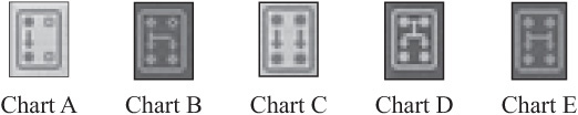
There are five signal flow charts used to describe the signal flow through the different effects (see Figure 10.1):
© Propellerhead Software AB.
![]() Chart A: This can be used as a mono-in, mono-out device.
Chart A: This can be used as a mono-in, mono-out device.
![]() Chart B: This can be used as a mono-in, stereo-out device. That means the effect will create a stereo effect, or it can also be used as a mono effect and panned.
Chart B: This can be used as a mono-in, stereo-out device. That means the effect will create a stereo effect, or it can also be used as a mono effect and panned.
![]() Chart C: Connecting both inputs and outputs in stereo makes this device a dual-mono effect because both left and right signals will be processed independently.
Chart C: Connecting both inputs and outputs in stereo makes this device a dual-mono effect because both left and right signals will be processed independently.
![]() Chart D: The left and right signals are summed, or combined, before being processed, which does not make it a true stereo signal. However, the effect itself is a stereo effect.
Chart D: The left and right signals are summed, or combined, before being processed, which does not make it a true stereo signal. However, the effect itself is a stereo effect.
![]() Chart E: This is a true stereo processor because the effect uses both left and right signals to generate a new signal. This process can be found in the RV7000 Advanced Reverb, which is discussed later in this chapter.
Chart E: This is a true stereo processor because the effect uses both left and right signals to generate a new signal. This process can be found in the RV7000 Advanced Reverb, which is discussed later in this chapter.
The remainder of this chapter is a guided tour through each of Reason’s real-time effects, with the exception of the Line 6 guitar and Bass Amp devices and the MClass Mastering Suite.
RV-7 Digital Reverb
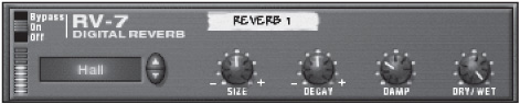
Reverberation is one of the most important effects needed to create ambience and space in your Reason songs. The RV-7 Digital Reverb is the first of two real-time stand-alone (there is another reverb in Kong) reverbs available in Reason 7 (see Figure 10.2) and is sure to help you add new life to your pads and snare drums.
© Propellerhead Software AB.
The RV-7 offers several presets, including the following:
![]() Hall: This simulates the characteristics of a standard-sized hall.
Hall: This simulates the characteristics of a standard-sized hall.
![]() Large Hall: This simulates the characteristics of a large hall.
Large Hall: This simulates the characteristics of a large hall.
![]() Hall 2: This sounds very similar to Hall 1, but with a brighter attack.
Hall 2: This sounds very similar to Hall 1, but with a brighter attack.
![]() Large Room: This simulates the characteristics of a large room with hard early reflections.
Large Room: This simulates the characteristics of a large room with hard early reflections.
![]() Medium Room: This simulates the characteristics of a medium-sized room with semi-hard walls.
Medium Room: This simulates the characteristics of a medium-sized room with semi-hard walls.
![]() Small Room: This simulates the characteristics of a much smaller room. Suitable for drums.
Small Room: This simulates the characteristics of a much smaller room. Suitable for drums.
![]() Gated: This provides a reverb that is fed through a gate with a quick release.
Gated: This provides a reverb that is fed through a gate with a quick release.
![]() Low Density: This makes a thin-sounding, low–CPU consumption reverb.
Low Density: This makes a thin-sounding, low–CPU consumption reverb.
![]() Stereo Echoes: This creates an echo reverberation that pans left and right.
Stereo Echoes: This creates an echo reverberation that pans left and right.
![]() Pan Room: This is similar to Stereo Echoes, but with softer attacks.
Pan Room: This is similar to Stereo Echoes, but with softer attacks.
TIP: Reverbs are without a doubt the most CPU-intensive of all real-time effects. With so many variables and algorithms needing to be calculated in real time, using several reverbs like the RV-7 in one Reason song can overload your computer’s processor. If you plan to use several instances of the RV-7 in one Reason song, choose the Low Density preset, which was designed to use less processing power than the others.
Once you have selected the preset you want to work with, you can begin to edit the preset with these available parameters:
![]() Size: This knob adjusts the size of the room. Decreasing this value causes the room size to shrink. Increasing the value has the opposite result. Also note that this knob is used to adjust the delay time when using the Stereo Echoes or Pan Room presets.
Size: This knob adjusts the size of the room. Decreasing this value causes the room size to shrink. Increasing the value has the opposite result. Also note that this knob is used to adjust the delay time when using the Stereo Echoes or Pan Room presets.
![]() Decay: This parameter adjusts the length of the reverb’s decay. Note that Decay is not used with the Gated preset.
Decay: This parameter adjusts the length of the reverb’s decay. Note that Decay is not used with the Gated preset.
![]() Damp: This parameter adjusts the equalization of the reverb effect. Increasing this value cuts the high frequencies, making for a warm and smooth effect.
Damp: This parameter adjusts the equalization of the reverb effect. Increasing this value cuts the high frequencies, making for a warm and smooth effect.
![]() Dry/Wet: This parameter determines the balance between a processed, or wet, signal and an unprocessed, or dry, signal. When using the RV-7 as a send or aux effect, you should set this knob to its maximum. When using it as an insert effect, you should set it in the middle, or 12 o’clock position, so you can hear both wet and dry signals at once.
Dry/Wet: This parameter determines the balance between a processed, or wet, signal and an unprocessed, or dry, signal. When using the RV-7 as a send or aux effect, you should set this knob to its maximum. When using it as an insert effect, you should set it in the middle, or 12 o’clock position, so you can hear both wet and dry signals at once.
The Matrix Pattern sequencer can be used to control the Decay parameter of the RV-7. Just route the Curve CV output of the Matrix to the Decay input on the back of the RV-7. Switch the Matrix from Note to Curve mode, select a note value, and create a curve for your RV-7 Decay.
DDL-1
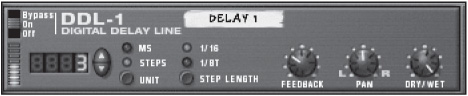
A delay effect is an echo of sorts, but not like that of a reverb. It is used to repeat synth phrases, thicken up pads, syncopate drum sounds, and introduce a funky tempo feeling to your songs. One of the best examples of this to be found in popular music is the guitar part for “Run Like Hell” by Pink Floyd. The whole rhythm of the song is based solely on a guitar part played through a delay in tempo with the song. Delay is simply one of those effects you cannot live without. It’s an effect that can be used on any instrument, even the less conventional ones, like bass synths. The DDL-1 (see Figure 10.3) is a delay that does it all and, what’s more, is incredibly easy to understand and use.
© Propellerhead Software AB.
![]() Delay Time: The window to the far left of the DDL-1 displays the currently selected delay time in either note-valued steps or in milliseconds. You can have a maximum of 16 steps or 2,000 milliseconds (approximately two seconds).
Delay Time: The window to the far left of the DDL-1 displays the currently selected delay time in either note-valued steps or in milliseconds. You can have a maximum of 16 steps or 2,000 milliseconds (approximately two seconds).
![]() Unit: This button is used to select either steps or milliseconds for the DDL-1. If you select steps, the delay effect synchronizes with the Reason sequencer. If you select milliseconds, the delay effect is in free time, meaning that it is not tempo related.
Unit: This button is used to select either steps or milliseconds for the DDL-1. If you select steps, the delay effect synchronizes with the Reason sequencer. If you select milliseconds, the delay effect is in free time, meaning that it is not tempo related.
![]() Step Length: This button is used to select the note value of the DDL-1 when it is set to steps. You can select between 1/16 notes (1/16) and 1/8 note triplets (1/8T).
Step Length: This button is used to select the note value of the DDL-1 when it is set to steps. You can select between 1/16 notes (1/16) and 1/8 note triplets (1/8T).
![]() Feedback: This knob sets the number of delay repeats.
Feedback: This knob sets the number of delay repeats.
![]() Pan: This knob pans the delay effect in the stereo field.
Pan: This knob pans the delay effect in the stereo field.
![]() Dry/Wet: This knob determines the balance between a processed, or wet, signal and an unprocessed, or dry, signal. When using the DDL-1 as a send or aux effect, you should set this knob to its maximum. When using it as an insert effect, you should set it in the middle, or 12 o’clock position, so you can hear both wet and dry signals at once.
Dry/Wet: This knob determines the balance between a processed, or wet, signal and an unprocessed, or dry, signal. When using the DDL-1 as a send or aux effect, you should set this knob to its maximum. When using it as an insert effect, you should set it in the middle, or 12 o’clock position, so you can hear both wet and dry signals at once.
The Matrix Pattern sequencer can be used to control the DDL-1 via CV input. Just connect the Curve CV, Note CV, or Gate CV outputs of the Matrix to one of these two parameters on the back of the DDL-1:
![]() Pan: Once this parameter is connected, the Matrix can pan your delay effect in Step mode. Increasing the amount of input on the back panel of the DDL-1 can intensify this effect.
Pan: Once this parameter is connected, the Matrix can pan your delay effect in Step mode. Increasing the amount of input on the back panel of the DDL-1 can intensify this effect.
![]() Feedback: Once this parameter is connected, the Matrix can control the amount of feedback in Step mode. Increasing the amount of input on the back panel of the DDL-1 can intensify this effect.
Feedback: Once this parameter is connected, the Matrix can control the amount of feedback in Step mode. Increasing the amount of input on the back panel of the DDL-1 can intensify this effect.
D-11 Foldback Distortion
The D-11 is a fantastic-sounding digital distortion effect (see Figure 10.4). It is a perfect and easy solution for adding a little more growl to your SubTractor bass lines or for going full-on industrial with Redrum. Controlled by just two parameters, the D-11 is a basic real-time effect that can be used as an insert or auxiliary send. It has two parameters:

© Propellerhead Software AB.
![]() Amount: This knob assigns the amount of distortion to be used.
Amount: This knob assigns the amount of distortion to be used.
![]() Foldback: This knob is used to add character to the shape of the distortion. At its minimum setting, the Foldback knob sounds dark and flat. At its maximum setting, the Foldback becomes the audio equivalent of nuclear meltdown by introducing a sharp and jarring effect into the mix.
Foldback: This knob is used to add character to the shape of the distortion. At its minimum setting, the Foldback knob sounds dark and flat. At its maximum setting, the Foldback becomes the audio equivalent of nuclear meltdown by introducing a sharp and jarring effect into the mix.
The Matrix can control the Amount parameter of the D-11. Just route the Curve CV output of the Matrix to the Amount input on the back of the D-11, and you’re set.
ECF-42 Envelope Controlled Filter
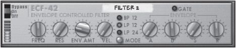
The ECF-42 is a combination filter/envelope generator that can be used to create pattern-controlled filter and envelope effects with any Reason device (see Figure 10.5). This effect should be used as an insert because it is more of a niche effect used for specific sounds rather than a universal effect such as a reverb or delay.
© Propellerhead Software AB.
Let’s look at the filter parameters of the ECF-42:
![]() Mode: This button is used to switch between the different filter modes (BP 12, LP 12, and LP 24). Also note that you can simply click on the name of the filter mode to select it.
Mode: This button is used to switch between the different filter modes (BP 12, LP 12, and LP 24). Also note that you can simply click on the name of the filter mode to select it.
![]() Freq: This knob controls the Filter Frequency of the ECF-42. When you use the ECF-42 in its static or filter-only mode, this knob controls the overall frequency of the audio. When you use this filter in combination with the envelope generator, this knob is used as a start and end frequency for the created filter sweep effect.
Freq: This knob controls the Filter Frequency of the ECF-42. When you use the ECF-42 in its static or filter-only mode, this knob controls the overall frequency of the audio. When you use this filter in combination with the envelope generator, this knob is used as a start and end frequency for the created filter sweep effect.
![]() Resonance: This knob, labeled “Res,” controls the resonance of the filter.
Resonance: This knob, labeled “Res,” controls the resonance of the filter.
![]() Envelope Amount: This knob, labeled “Env Amt,” is used to specify how much the filter frequency will be affected by the triggered envelope.
Envelope Amount: This knob, labeled “Env Amt,” is used to specify how much the filter frequency will be affected by the triggered envelope.
![]() Velocity: This knob, labeled “Vel,” is used to specify how much the gate velocity affects the envelope.
Velocity: This knob, labeled “Vel,” is used to specify how much the gate velocity affects the envelope.
The envelope parameters of the ECF-42 are available only when triggered by another Reason device, such as a Matrix or Dr. Octo Rex (see the upcoming sidebar for more information). Once the envelope is triggered by another Reason device, you can use any of these standard envelope parameters:
![]() Attack (A)
Attack (A)
![]() Decay (D)
Decay (D)
![]() Sustain (S)
Sustain (S)
![]() Release (R)
Release (R)
Triggering the Envelope: Unlike most of the other real-time effects in Reason, the ECF-42 does not function completely as an independent effect and requires an additional Reason device to trigger the envelope. This is done very easily by routing the gate output of any Reason device that has a gate output on the back, such as Redrum, Dr. Octo Rex, or the Matrix.
Here’s how to set it up with a Dr. Octo Rex:
1. In any Reason song, create a Dr. Octo Rex and load it up with any available REX file. Click the Copy Loop to Track button to send it to the sequencer.
2. Click on the Dr. Octo Rex to select it and then select the ECF-42 Envelope Controlled Filter from the Create menu. Reason automatically sets up the ECF-42 as an insert effect for Dr. Octo Rex.
3. Press the Tab key to flip the Rack screen.
4. Route the gate output of Dr. Octo Rex to the env gate input on the back of the ECF-42.
5. Press the Tab key again and click Play.
You should now see the Gate LED on the ECF-42 light up because it is receiving gate information from Dr. Octo Rex. At this point, you can use the Envelope parameters.
The Matrix can control the Frequency, Decay, and Resonance parameters of the ECF-42. Just route any of the CV outputs of the Matrix to any of the three available ECF-42 parameters, and you’re set.
CF-101 Chorus/Flanger
The CF-101 is a combination chorus/flanger effect device (see Figure 10.6). A chorus/flanger effect is commonly used to add depth and ambience to a sound by introducing a short delay to the audio signal. That delayed signal is then mixed with the original dry signal, creating a much larger sound than before. The size and broadness of the delayed signal are determined by the set delay time, feedback, and LFO modulation.

© Propellerhead Software AB.
TIP: To really understand the magic of a chorus/flanger effect, you should hear these beauties in action. Some of the best examples can be found in classic rock tunes of the 1970s and ’80s. For example, the vocal track from “In The Air Tonight” by Phil Collins is drenched in chorus, whereas “Never Let Me Down Again” by Depeche Mode and “Barracuda” by Heart are examples of flanging at its best. Sure, they may be “moldy golden oldies” to some, but you can really benefit from exploring the groundbreaking work found in these tunes.
Let’s look at the CF-101 parameters:
![]() Delay: This knob sets the delay time needed to create the chorus/flanger. For best results, use short delay times to create a flanger effect and medium-to-long delay times for chorus effects.
Delay: This knob sets the delay time needed to create the chorus/flanger. For best results, use short delay times to create a flanger effect and medium-to-long delay times for chorus effects.
![]() Feedback: This knob controls the amount of effect being fed back into the input, which gives character to the effect.
Feedback: This knob controls the amount of effect being fed back into the input, which gives character to the effect.
![]() LFO Rate: This knob controls the modulation rate of the LFO. Increasing this parameter speeds up the frequency of oscillation.
LFO Rate: This knob controls the modulation rate of the LFO. Increasing this parameter speeds up the frequency of oscillation.
![]() LFO Sync: This button synchronizes the LFO Rate setting to the tempo of the Reason sequencer. Note that when this button is activated, the LFO Rate knob displays note values rather than the standard numeric value.
LFO Sync: This button synchronizes the LFO Rate setting to the tempo of the Reason sequencer. Note that when this button is activated, the LFO Rate knob displays note values rather than the standard numeric value.
![]() LFO Modulation Amount: This knob, labeled “Mod Amt,” is used to assign a depth to the LFO modulation.
LFO Modulation Amount: This knob, labeled “Mod Amt,” is used to assign a depth to the LFO modulation.
![]() Send Mode: This button is used to properly integrate the CF-101 with the other Reason devices. When it is activated, the CF-101 is in Send mode, which means that the device outputs only the modulated signal, making it possible to use the Aux send knob to mix in the additional dry signal. When it is not active, the CF-101 is used as an insert effect, where the device outputs a mix of the dry and wet signal.
Send Mode: This button is used to properly integrate the CF-101 with the other Reason devices. When it is activated, the CF-101 is in Send mode, which means that the device outputs only the modulated signal, making it possible to use the Aux send knob to mix in the additional dry signal. When it is not active, the CF-101 is used as an insert effect, where the device outputs a mix of the dry and wet signal.
Aside from parameters on the front of the device, the Matrix Pattern sequencer can also modify the CF-101. Press the Tab key to flip the Rack screen, and you will find two CV inputs: one for the Delay parameter and one for the LFO Rate parameter. Just route the Curve, Note, or Gate CV outputs of the Matrix to either of these parameters and experiment.
PH-90 Phaser
The PH-90 is a sweeping effect perfect for use with guitar samples, Rhodes piano patches, or pads (see Figure 10.7). At times, it can be confused with a standard chorus/flanger effect, but a phaser is a much different monster once you look under the hood.

© Propellerhead Software AB.
A phaser shifts portions of an audio signal out of phase and then sends that signal back to the original signal, causing narrow bands (called notches) of the frequency spectrum to be filtered out. The aforementioned sweeping effect happens when these notches are adjusted.
The PH-90 has four adjustable notches in the frequency spectrum that can be modified by way of seven parameters:
![]() Frequency: This knob, labeled “Freq,” assigns the frequency of the first notch. Once this is set, the remaining three notches move in parallel in the frequency spectrum.
Frequency: This knob, labeled “Freq,” assigns the frequency of the first notch. Once this is set, the remaining three notches move in parallel in the frequency spectrum.
![]() Split: This knob changes the distance between each notch. This alters the character of the overall effect.
Split: This knob changes the distance between each notch. This alters the character of the overall effect.
![]() Width: This knob adjusts the width of the notches. Increasing this parameter creates a very deep effect, while also making the overall sound hollow.
Width: This knob adjusts the width of the notches. Increasing this parameter creates a very deep effect, while also making the overall sound hollow.
![]() LFO Rate: This knob controls the modulation rate of the LFO. Increasing this value speeds up the frequency of oscillation.
LFO Rate: This knob controls the modulation rate of the LFO. Increasing this value speeds up the frequency of oscillation.
![]() LFO Sync: This button synchronizes the LFO Rate setting to the tempo of the Reason sequencer. Note that when this button is activated, the LFO Rate knob displays note values rather than the standard numeric value.
LFO Sync: This button synchronizes the LFO Rate setting to the tempo of the Reason sequencer. Note that when this button is activated, the LFO Rate knob displays note values rather than the standard numeric value.
![]() LFO Frequency Modulation: This knob, labeled “F. Mod,” assigns the depth of LFO modulation.
LFO Frequency Modulation: This knob, labeled “F. Mod,” assigns the depth of LFO modulation.
![]() Feedback: This knob is used to alter the tone of the phaser, in much the same way as a Resonance knob on a filter.
Feedback: This knob is used to alter the tone of the phaser, in much the same way as a Resonance knob on a filter.
The Matrix Pattern sequencer can also modify the PH-90. Press the Tab key to flip the Rack screen, and you will find two CV inputs: one for the LFO Frequency and one for the LFO Rate parameters. Just route the Curve, Note, or Gate CV outputs of the Matrix to either of these parameters and experiment.
Here’s an exercise to demonstrate how to use the PH-90 with Dr. Octo Rex. Be sure to create a new song and load it with a Dr. Octo Rex. Also, load a REX file and send it to its sequencer track.
1. Select the Dr. Octo Rex by clicking on it once. Then select PH-90 Phaser from the Create menu. This will automatically connect the PH-90 to the Dr. Octo Rex to be used as an insert effect.
2. Click Play, and you will hear the PH-90 in action. By default, it already sounds great, but would probably sound even better if it were synced up to the tempo of the Reason song.
3. Click the Sync button to synchronize the PH-90 effect with the song tempo. Then adjust the Rate knob until it reads 4/4, which means that the phasing effect will recycle every bar.
4. Adjust the Split knob to 0. Notice the extra sweep that has been introduced to the low end.
5. Adjust the Width knob to its maximum setting. Notice that the high and low frequencies are accented, but not the mid frequencies, which makes the overall sound hollow.
6. Experiment with setting the Feedback knob to add a singing tone to the mix.
UN-16 Unison
The UN-16 Unison module can be thought of as a simple and straightforward chorus effect (see Figure 10.8). When you use the available parameters, it produces a set number of voices that are each slightly delayed and detuned by way of low-frequency noise. This produces a very thick stereo-friendly chorus that can be used on vocal samples, guitar/drum loops, and so on.

© Propellerhead Software AB.
Let’s look at the UN-16 parameters:
![]() Voice Count: This parameter assigns the number of voices to be produced. You can select 4, 8, or 16 individual voices.
Voice Count: This parameter assigns the number of voices to be produced. You can select 4, 8, or 16 individual voices.
![]() Detune: This knob increases or decreases the detuning of the individual voices.
Detune: This knob increases or decreases the detuning of the individual voices.
![]() Dry/Wet: This knob determines the balance between a processed, or wet, signal and an unprocessed, or dry, signal. When using the UN-16 as a send or aux effect, you should set this knob to its maximum. When using it as an insert effect, you should set it in the middle, or 12 o’clock position, so you can hear both wet and dry signals at once.
Dry/Wet: This knob determines the balance between a processed, or wet, signal and an unprocessed, or dry, signal. When using the UN-16 as a send or aux effect, you should set this knob to its maximum. When using it as an insert effect, you should set it in the middle, or 12 o’clock position, so you can hear both wet and dry signals at once.
The Matrix Pattern sequencer can control the detune parameter of the UN-16. Just connect the Curve CV output of the Matrix to the Detune input on the back of the UN-16.
PEQ-2
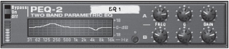
The PEQ-2 is a two-band parametric EQ that allows very precise control over the equalization curve of any Reason device (see Figure 10.9). There have been a few additions to the EQ department since the PEQ-2 was released that have a much wider feature set. Still, the PEQ-2 can be used when you just need simple equalization.
© Propellerhead Software AB.
The two bands of equalization, EQ A and EQ B, are controlled independently in the interface of the PEQ-2. EQ A is always active and ready to use when an instance of the PEQ-2 is created in a Reason song. To use EQ B, you must first activate it by clicking the B button, found in the lower-center portion of the interface. Once it is activated, its individual parameters are at your disposal.
The graphical display in the left portion of the PEQ-2 is used to show the frequency response curve as it is being created by the EQ parameters. This is a fantastic visual aid that helps you sculpt your EQ curve.
Let’s look at the parameters of the PEQ-2:
![]() Frequency: This knob, labeled “Freq,” assigns the center of the EQ curve. When changing this setting, you should first increase the Gain parameter to hear the effect. The range is 31 Hz to 16 Hz.
Frequency: This knob, labeled “Freq,” assigns the center of the EQ curve. When changing this setting, you should first increase the Gain parameter to hear the effect. The range is 31 Hz to 16 Hz.
![]() Q: This knob determines the frequency width of the EQ curve around the set center frequency.
Q: This knob determines the frequency width of the EQ curve around the set center frequency.
![]() Gain: This knob boosts and cuts the gain of the EQ curve.
Gain: This knob boosts and cuts the gain of the EQ curve.
The Matrix can control the Freq A and Freq B settings by connecting the Curve CV, Note CV, or Gate CV outputs of the Matrix to the Freq 1 or Freq 2 inputs on the back of the PEQ-2.
COMP-01 Compressor
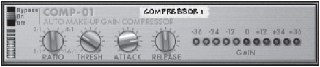
The COMP-01 is real-time compressor that is typically used to level out audio signals that are too loud in the mix and are in danger of digitally clipping. The COMP-01 is a great solution to combat this problem and can be used as an insert effect or send effect (see Figure 10.10). Its parameters are as follows:
© Propellerhead Software AB.
![]() Ratio: This knob sets the gain reduction of the audio signal according to the set threshold.
Ratio: This knob sets the gain reduction of the audio signal according to the set threshold.
![]() Threshold: This knob, labeled “Thresh,” sets the level that dictates when the compressor effect will kick in. Any audio signal that meets this set level or goes above it is compressed, whereas signals that fall below this level are not affected.
Threshold: This knob, labeled “Thresh,” sets the level that dictates when the compressor effect will kick in. Any audio signal that meets this set level or goes above it is compressed, whereas signals that fall below this level are not affected.
![]() Attack: This knob adjusts the attack of the compression effect.
Attack: This knob adjusts the attack of the compression effect.
![]() Release: This knob adjusts the length of time needed before the audio signal is unaffected by the COMP-01, once its level has fallen under the threshold. At its lowest setting, a short release causes a pumping sound, which is good for kick drums. At its mid to high settings, the release becomes long and sustained, which is good for pads or pianos.
Release: This knob adjusts the length of time needed before the audio signal is unaffected by the COMP-01, once its level has fallen under the threshold. At its lowest setting, a short release causes a pumping sound, which is good for kick drums. At its mid to high settings, the release becomes long and sustained, which is good for pads or pianos.
![]() Gain: This meter displays the amount of gain reduction and increase in decibels.
Gain: This meter displays the amount of gain reduction and increase in decibels.
To use the COMP-01 as an insert effect (which is its intended use), refer to the “PEQ-2” section earlier in this chapter.
The BV512 Vocoder/Equalizer
One of the coolest effects in Reason 7 is the BV512 vocoder (see Figure 10.11). This effect is commonly used to create robotic voices in dance and performance music. Another popular use of a vocoder is to create a “choir of synthetic voices” as heard in songs by Moby and New Order. Possibly the single most famous use of a vocoder in popular music is the opening of the 1980s hit “Mr. Roboto” by Styx. A beautiful and very artistic use of vocoder can be found in another 1980s track, “O Superman,” by Laurie Anderson.

© Propellerhead Software AB.
What Is a Vocoder?
A vocoder is an effect that uses two separate sources of input to create a new audio signal by applying the frequency bands of one signal to the other. These two separate audio sources are as follows:
![]() The carrier. The carrier is ideally an audio source that is constantly generating sound. A good example of this is a string pad playing from the SubTractor in a sequence that is looped continuously.
The carrier. The carrier is ideally an audio source that is constantly generating sound. A good example of this is a string pad playing from the SubTractor in a sequence that is looped continuously.
![]() The modulator. The modulator is typically an audio source such as a spoken voice or vocal track. Another typically used modulator is a drum loop for creating rhythmically enhanced sounds.
The modulator. The modulator is typically an audio source such as a spoken voice or vocal track. Another typically used modulator is a drum loop for creating rhythmically enhanced sounds.
Once you have these two elements, they are then routed to their appropriate vocoder inputs. The modulator is divided into a set number of bands (4, 8, 16, 32, or 512) by using band-pass filters. These separate bands are then sent to an envelope follower, which is a device that continuously monitors and analyzes the signal levels. Meanwhile, the carrier is processed with the same number of bands as the modulator. The same frequency ranges used in the modulator’s band-pass filters are also applied to the carrier. This way, the carrier will have the same frequency characteristics as the modulator. That means if the modulator gets louder or more dynamic in shape, the carrier will emulate this.
TIP: If you want to hear good audio examples of vocoding, listen to just about any CD by Laurie Anderson (“O Superman”), Daft Punk (“Around the World”), Air (“Remember”), or Zapp and Roger (“More Bounce to the Ounce”).
Let’s look at the basic parameters of the BV512:
![]() Level meters: These meters display the signal level of the carrier and the modulator.
Level meters: These meters display the signal level of the carrier and the modulator.
![]() Band switch: This switches between the number of filter bands (4, 8, 16, 32, or 512).
Band switch: This switches between the number of filter bands (4, 8, 16, 32, or 512).
![]() Equalizer/Vocoder switch: This switches the BV512 between Vocoder mode and Equalizer mode. Note that when the BV512 is in Equalizer mode, the modulator input is not used.
Equalizer/Vocoder switch: This switches the BV512 between Vocoder mode and Equalizer mode. Note that when the BV512 is in Equalizer mode, the modulator input is not used.
![]() Modulation Levels display: This displays the overall spectrum of the modulation signal.
Modulation Levels display: This displays the overall spectrum of the modulation signal.
![]() Frequency Band Level Adjust: This displays the levels of the individual filter bands. When this section is used in Vocoder mode, each band adjusts the sound and shape of the vocoder. When this section is used in Equalizer mode, each band adjusts the amplitude of the individual frequencies in the EQ curve. After making adjustments to the individual bands, you can use the Reset Band Levels option from the Edit menu.
Frequency Band Level Adjust: This displays the levels of the individual filter bands. When this section is used in Vocoder mode, each band adjusts the sound and shape of the vocoder. When this section is used in Equalizer mode, each band adjusts the amplitude of the individual frequencies in the EQ curve. After making adjustments to the individual bands, you can use the Reset Band Levels option from the Edit menu.
![]() Hold: When activated, this button freezes the current filter settings. The modulator signal no longer affects the carrier in this mode. Clicking it again releases the filter settings.
Hold: When activated, this button freezes the current filter settings. The modulator signal no longer affects the carrier in this mode. Clicking it again releases the filter settings.
![]() Attack: This affects the overall attack of the frequency bands. Increasing the Attack setting can create some very cool pad sounds. Note that when the BV512 is in Equalizer mode, this parameter is not available.
Attack: This affects the overall attack of the frequency bands. Increasing the Attack setting can create some very cool pad sounds. Note that when the BV512 is in Equalizer mode, this parameter is not available.
![]() Decay: This parameter affects the overall decay of the frequency bands. As with the Attack, this parameter is not available when the BV512 is used as an equalizer.
Decay: This parameter affects the overall decay of the frequency bands. As with the Attack, this parameter is not available when the BV512 is used as an equalizer.
![]() Shift: This shifts the carrier signal filters up and down, creating a sweeping effect.
Shift: This shifts the carrier signal filters up and down, creating a sweeping effect.
![]() High Frequency Emphasis: This knob, labeled “HF Emph,” increases the high frequencies in the carrier signal.
High Frequency Emphasis: This knob, labeled “HF Emph,” increases the high frequencies in the carrier signal.
![]() Dry/Wet: This knob mixes between the unprocessed (dry) signal and the processed (wet) signal.
Dry/Wet: This knob mixes between the unprocessed (dry) signal and the processed (wet) signal.
The BV512 as an Equalizer
The BV512 can also be used as a graphic equalizer. Capable of supporting up to 512 bands of equalization, the BV512 is perfect for enhancing individual devices in a Reason song or can even be used as a mastering equalizer.
Follow these steps to learn how to use the BV512 as a mastering equalizer:
1. Near the top of the Rack screen, click the Show Insert FX button on the Master Section Device.
2. Right-click on the Master Section Device and select Clear Insert FX from the menu.
3. Locate the BV512 Vocoder device in the Device Palette screen of the Tool Window and drag the BV512 Vocoder into the Insert slot of the Master Section.
4. If the Bypass button on the Master Section is lit blue, click on it so that the Master Section insert effects will not be bypassed.
5. On the BV512 Vocoder, set the Equalizer/Vocoder switch to Equalizer. Also, set the Band switch to 512 for the best-quality equalization. (Read the upcoming note for details.)
At this point, you can now load some Reason devices, sequence them, and play them through the BV512 as a mastering EQ. Feel free to add an MClass Maximizer below the BV512 Vocoder if you so desire!
NOTE: As you know, the BV512 supports up to 512 bands of EQ, but what does this really mean? If you use the Band switch to change between 32 bands and 512 bands of EQ, there is no visual difference in the interface of the BV512, but there is a noticeable auditory difference, thanks to Fast Fourier Transform (FFT). FFT is a very detailed and precise form of analysis and processing in which waveforms are represented as a sum of sines and cosines. (Math geeks rejoice!) That means using the BV512 as a vocoder or as an EQ in 512FFT mode produces very precise and detailed control over the shaping of the effect. One point to keep in mind is that when you are making adjustments to the BV512 in 512FFT mode, a majority of the available bands in the interface will control the high frequencies rather than the low frequencies.
Basic Vocoding Tutorial
Let’s apply what you have just learned about vocoding by going through a basic vocoding tutorial. In this section, you open a Reason song that I have prepared; it consists of an NN-19 (the modulator) playing a single sample, a SubTractor (the carrier) playing chords, and the BV512 Vocoder. Through this step-by-step method, you learn how to route the carrier and modulator to the BV512, adjust the frequency band, and create a unique signal that you can edit further by using the synth parameters of the SubTractor.
NOTE: Before you start this tutorial, take a minute to visit the Cengage Learning website (www.cengageptr.com), where you will find a Reason song called “Vocoder Tutorial.” This song file is a published song, which means that all the elements specifically created for this tutorial are self-contained in the song file.
1. Open the “Vocoder Tutorial” song. You will see the DDL-1 delay, a SubTractor, the NN-19, and the BV512 at the bottom. The NN-19 has a loaded sample of my voice, and the SubTractor has the Bowy patch loaded. Also notice that there is a sequence written for both the SubTractor and the NN-19, but if you click Play, you won’t hear anything because the audio has not yet been routed.
2. Press the Tab key to flip the Rack screen. This gives you a perfect starting point to begin routing your carrier and modulator.
3. Route the output of the SubTractor to the carrier input left of the BV512 (see Figure 10.12).

© Propellerhead Software AB.
4. Route the left output of the NN-19 to the modulator input on the BV512 (see Figure 10.13).
5. Route just the left output of the BV512 to the channel 1 left input of the Mix Channel of the NN-XT. This is a mono signal.
6. Click Play on the Transport panel. You should now hear the BV512 in action. It should be a strong signal that is very bass-heavy and slightly distorted. That means some adjustments will need to be made to the frequency band level section of the BV512.
7. Because this is your first time using the BV512, use the Band switch to switch to the 16-band display, and make some adjustments to the lower frequency bands (see Figure 10.14).

© Propellerhead Software AB.

© Propellerhead Software AB.
This should give you a pretty good idea of how the BV512 works. You can experiment further by changing the band range of the BV512, making additional adjustments to the synth parameters of the SubTractor, or replacing the SubTractor with the Malström for a whole new sound.
Using Dr. Octo Rex as the Modulator: Another interesting application for the BV512 is to use a drum loop as the source of modulation. This creates a very interesting rhythmically driven audio signal. Try the following exercise:
1. Create an instance of Dr. Octo Rex and load a 1/16-note patterned REX file. Something from the Abstract Hip-Hop folder in the Reason Factory Sound Bank should work well.
2. Click the To Track button on the Dr. Octo Rex interface to load the REX file into the Reason sequencer.
3. Press the Tab key to flip the Rack screen. Disconnect the NN-19 from the BV512.
4. Disconnect Dr. Octo Rex from its Mix Channel. Connect the left output of Dr. Octo Rex to the modulator input of the BV512.
5. Click Play to hear the rhythmic bliss of vocoding in action. Try to add some delay to the signal, or use some of the synth parameters of either Dr. Octo Rex or the SubTractor for a whole new sound.
Automation
All the parameters in the BV512 can be automated in the same way as any Reason device. If you would rather draw in your automation data than record it in real time, the only hoop you have to jump through to begin automating is to create a sequencer track. You can see how by working through the following exercise. Before you begin, start a new Reason song and create an NN-19 and a BV512.
1. Right-click on the BV512 and select Create Track for Vocoder 1. This creates a sequencer track that is automatically routed to the BV512.
2. Right-click on the vocoder track and select Parameter Automation.
3. A window pops up giving you a list of parameters to select. Select the ones you want and click OK.
4. The Reason sequencer now displays these parameters as lanes on the vocoder sequencer track. Switch to the Edit mode and draw your automation moves.
For more on automation, check out Chapter 12, “Automation.”
CV Connections
As if it couldn’t get any better, the BV512 offers many individual inputs and outputs on the back of the device that allow for some interesting routing possibilities (see Figure 10.15).

© Propellerhead Software AB.
![]() Frequency band outputs: These CV outputs use the amplitude of an individual frequency band to control the parameter inputs of other Reason devices. For example, you could route the output of band 8 to the FM Amount input of the SubTractor.
Frequency band outputs: These CV outputs use the amplitude of an individual frequency band to control the parameter inputs of other Reason devices. For example, you could route the output of band 8 to the FM Amount input of the SubTractor.
![]() Frequency band inputs: These CV inputs can be controlled by the Matrix to alter the amplitude of each frequency band in the BV512. Note that once you make a connection from the Matrix to a specific frequency band, the Matrix exclusively controls that band’s amplitude.
Frequency band inputs: These CV inputs can be controlled by the Matrix to alter the amplitude of each frequency band in the BV512. Note that once you make a connection from the Matrix to a specific frequency band, the Matrix exclusively controls that band’s amplitude.
![]() Shift: This input controls the Shift parameter on the front of the device and can be used to create fantastic sweeping effects.
Shift: This input controls the Shift parameter on the front of the device and can be used to create fantastic sweeping effects.
![]() Hold: This input is to operate the Hold parameter and can be used to create a step-driven vocoder effect. It’s perfect for creating percussive vocoder stabs on vocals and pads. Note that you must use the Gate CV output of the Matrix to make this input work.
Hold: This input is to operate the Hold parameter and can be used to create a step-driven vocoder effect. It’s perfect for creating percussive vocoder stabs on vocals and pads. Note that you must use the Gate CV output of the Matrix to make this input work.
Scream 4 Sound Destruction Unit
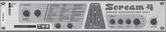
Aside from the comical Wes Craven-esque name (programmers always have a good sense of humor), the appropriately titled Scream 4 is a digital distortion effect that takes vocals, drums, and synth patches to a whole new level (see Figure 10.16). Divided into three sections (Damage, Cut, and Body), Scream 4 can shape, mold, and destroy any audio signal it comes into contact with. Another welcome addition to Scream 4 and the upcoming RV7000 (discussed later in this chapter) is the ability to load, edit, and save customized presets. Scream 4 already comes with a lot of great sounding presets, but it never hurts to make your own. If you were looking for a distortion box with more to offer than the D-11, this is it!
© Propellerhead Software AB.
The Damage Section
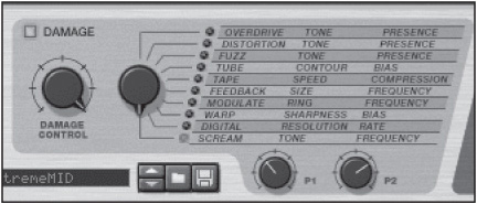
Let’s look at the various parameters of Scream
4. This section looks at the parameters and presets for the Damage section (see Figure 10.17).
© Propellerhead Software AB.
![]() Damage: This button turns the Damage section on and off.
Damage: This button turns the Damage section on and off.
![]() Damage Control: This knob is used to assign an amount of input gain to Scream 4. The higher the value, the more distortion there is.
Damage Control: This knob is used to assign an amount of input gain to Scream 4. The higher the value, the more distortion there is.
![]() Damage Type: This knob lets you select the type of distortion.
Damage Type: This knob lets you select the type of distortion.
![]() P1/P2: These knobs work differently with each Damage type. These types are covered next.
P1/P2: These knobs work differently with each Damage type. These types are covered next.
There are 10 Damage types available with Scream 4:
![]() Overdrive: This standard analog-type distortion responds well to variable dynamics. When it is selected, the P1 knob is used as a tone control. The P2 knob controls the presence, which increases the mid to high frequencies before it’s passed through the distortion effect.
Overdrive: This standard analog-type distortion responds well to variable dynamics. When it is selected, the P1 knob is used as a tone control. The P2 knob controls the presence, which increases the mid to high frequencies before it’s passed through the distortion effect.
![]() Distortion: This preset is similar to the Overdrive preset, but it is capable of creating a much thicker distortion effect. Note that the P1 and P2 knobs work the same here as they do with the Overdrive preset.
Distortion: This preset is similar to the Overdrive preset, but it is capable of creating a much thicker distortion effect. Note that the P1 and P2 knobs work the same here as they do with the Overdrive preset.
![]() Fuzz: This preset is a heavy distortion that is strong even at low Damage Control settings. Note that the P1 and P2 knobs work the same as they do with the Overdrive preset.
Fuzz: This preset is a heavy distortion that is strong even at low Damage Control settings. Note that the P1 and P2 knobs work the same as they do with the Overdrive preset.
![]() Tube: This preset simulates a classic tube distortion (à la Led Zeppelin or Jimi Hendrix). When you use this preset, the P1 knob acts as a contour or high-pass filter. The P2 knob controls the bias, or balance, of the tube distortion. When the P2 knob is set to a12o’clock position, the bias is very balanced in shape. When the P2 knob is set to its maximum resolution, it creates an uneven balance to the distortion, which sounds very close to a tube-driven amplifier.
Tube: This preset simulates a classic tube distortion (à la Led Zeppelin or Jimi Hendrix). When you use this preset, the P1 knob acts as a contour or high-pass filter. The P2 knob controls the bias, or balance, of the tube distortion. When the P2 knob is set to a12o’clock position, the bias is very balanced in shape. When the P2 knob is set to its maximum resolution, it creates an uneven balance to the distortion, which sounds very close to a tube-driven amplifier.
![]() Tape: This preset is a simulation of tape saturation, which can add compression and punch to the distortion. The P1 knob acts as a tape speed, which helps to preserve the higher frequencies when set to high speeds. The P2 knob controls the compression ratio.
Tape: This preset is a simulation of tape saturation, which can add compression and punch to the distortion. The P1 knob acts as a tape speed, which helps to preserve the higher frequencies when set to high speeds. The P2 knob controls the compression ratio.
![]() Feedback: This preset is a combination of heavy distortion and looped feedback. Feedback is created when a sound source is fed back to itself. A good example is an electric guitar or microphone that is placed too close to its amplifier or speaker. The Damage Control knob assigns the amount of gain to the feedback loop, and the P1 and P2 knobs control the size and “howl,” or frequency, of the feedback, respectively.
Feedback: This preset is a combination of heavy distortion and looped feedback. Feedback is created when a sound source is fed back to itself. A good example is an electric guitar or microphone that is placed too close to its amplifier or speaker. The Damage Control knob assigns the amount of gain to the feedback loop, and the P1 and P2 knobs control the size and “howl,” or frequency, of the feedback, respectively.
![]() Modulate: This preset creates a distortion that resonates by combining two copies of itself before it is fed through a distortion. The P1 knob controls the resonance ring, and the P2 knob controls the filter frequency.
Modulate: This preset creates a distortion that resonates by combining two copies of itself before it is fed through a distortion. The P1 knob controls the resonance ring, and the P2 knob controls the filter frequency.
![]() Warp: This preset creates a strong, stinging distortion by multiplying its incoming signal with itself. The P1 knob controls the sharpness of the distortion, and the P2 knob controls the bias, or balance, of the distortion.
Warp: This preset creates a strong, stinging distortion by multiplying its incoming signal with itself. The P1 knob controls the sharpness of the distortion, and the P2 knob controls the bias, or balance, of the distortion.
![]() Digital: This preset is meant to be used as a low-fidelity, gritty distortion. The P1 knob is used to alter the bit depth from the highest resolution possible to a down-and-dirty single bit of resolution. The P2 knob alters the sample rate of the distortion and ranges from clean and pristine to crunchy and static.
Digital: This preset is meant to be used as a low-fidelity, gritty distortion. The P1 knob is used to alter the bit depth from the highest resolution possible to a down-and-dirty single bit of resolution. The P2 knob alters the sample rate of the distortion and ranges from clean and pristine to crunchy and static.
![]() Scream: This preset is similar to the Fuzz preset, but includes a band-pass filter including high resonance and gain before distorting. The P1 knob controls the tone of the distortion, and the P2 knob controls the filter frequency.
Scream: This preset is similar to the Fuzz preset, but includes a band-pass filter including high resonance and gain before distorting. The P1 knob controls the tone of the distortion, and the P2 knob controls the filter frequency.
The Cut Section
The Cut section of Scream 4 acts as EQ controls, allowing for many creative possibilities in carving and shaping an interesting EQ curve for your distortion (see Figure 10.18). Click on the Cut button to activate the EQ. At this point, you can adjust the low, mid, and high bands of equalization to your liking. At any time, you can reset any of the three bands by Ctrl-clicking (Windows) or Command-clicking (Mac) on the band slider to reset it to its default position.

© Propellerhead Software AB.
The Body Section
The Body section of Scream 4 is used to create different effects, such as speaker cabinet simulations and auto-wahs (for us guitarists), by placing the signal in different simulated enclosures (see Figure 10.19). Five body types can be selected and then edited by resonance and scale parameters.
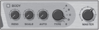
© Propellerhead Software AB.
![]() Body: This button switches the Body section on and off.
Body: This button switches the Body section on and off.
![]() Resonance: This knob, labeled “Reso,” creates a resonance effect for the selected body type.
Resonance: This knob, labeled “Reso,” creates a resonance effect for the selected body type.
![]() Scale: This knob controls the size of the selected body. Note that this knob is inverted; turning the knob clockwise creates a smaller size, whereas turning it counterclockwise increases the size.
Scale: This knob controls the size of the selected body. Note that this knob is inverted; turning the knob clockwise creates a smaller size, whereas turning it counterclockwise increases the size.
![]() Auto: This knob controls the amount of the envelope follower (see the upcoming sidebar).
Auto: This knob controls the amount of the envelope follower (see the upcoming sidebar).
![]() Type: This knob switches between one of five available body types.
Type: This knob switches between one of five available body types.
The Envelope Follower: The envelope follower is used to change the body scale according to the incoming dynamic level. The louder the incoming sound, the more the scale parameter is increased. This creates what is commonly known as an “auto-wah” effect, which is set by the Auto knob.
To demonstrate the versatility of this effect, try the following exercise. Before you begin, start a new Reason song.
1. Create a Dr. Octo Rex and load a REX file from either the Abstract Hip-Hop folder or the Techno folder in the Reason Factory Sound Bank. Click the To Track button to load the Dr. Octo Rex pattern into the Reason sequencer.
2. Create a Scream 4 and route it to be used as an insert effect.
3. Activate the Body section, select body type B, and turn the Auto knob clockwise.
4. Adjust the Resolution knob.
5. Click Play. Notice how the body scale opens up with the various dynamics of the REX loop.
The CV Connections
Using CV outputs can enable the Matrix to control any of four Scream 4 parameters.
![]() Damage Control: This changes the amount of distortion.
Damage Control: This changes the amount of distortion.
![]() P1: This increases or decreases the P1 parameter. Note that the damage type determines what this parameter affects.
P1: This increases or decreases the P1 parameter. Note that the damage type determines what this parameter affects.
![]() P2: This increases or decreases the P2 parameter. Note that the damage type determines what this parameter affects.
P2: This increases or decreases the P2 parameter. Note that the damage type determines what this parameter affects.
![]() Scale: This increases or decreases the size of the selected body.
Scale: This increases or decreases the size of the selected body.
Additionally, Scream 4 includes an Auto CV output, which can be routed to the CV input of another Reason device. For example, Scream 4 could be routed to a modulation parameter of the SubTractor or Malström.
RV7000 Advanced Reverb
The RV7000 is a true stereo professional reverb effect that sounds too good to be true (see Figure 10.20). It has nine reverb and echo algorithms that can be used along with an EQ and gate for molding and shaping your reverb in ways that just can’t be done by most hardware and software reverbs.

© Propellerhead Software AB.
The Main Panel
The RV7000 is a two-part effect unit, much the same way that the NN-XT is a two-part sampler. When you first load the RV7000, the part of the device you see is the main panel, which controls the global parameters of the device (see Figure 10.21).
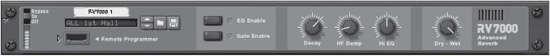
© Propellerhead Software AB.
Notice that the RV7000 has a Patch Browser in the left corner of the main panel. This makes it possible to load, edit, and save customized patches for the device.
Take a look at the global parameters:
![]() EQ Enable: This button switches the EQ section off and on.
EQ Enable: This button switches the EQ section off and on.
![]() Gate Enable: This button switches the Gate section off and on.
Gate Enable: This button switches the Gate section off and on.
![]() Decay: This knob controls the rate of decay in a reverb or the amount of feedback in an echo algorithm.
Decay: This knob controls the rate of decay in a reverb or the amount of feedback in an echo algorithm.
![]() High Frequency Damp: This knob, labeled “HF Damp,” assigns an amount of decay time for the high frequencies in the reverb. Increasing this value makes the reverb sound warm and dull.
High Frequency Damp: This knob, labeled “HF Damp,” assigns an amount of decay time for the high frequencies in the reverb. Increasing this value makes the reverb sound warm and dull.
![]() High EQ: This knob, labeled “Hi EQ,” controls the high shelving EQ. Increase the value of this parameter to boost the high frequencies in the reverb.
High EQ: This knob, labeled “Hi EQ,” controls the high shelving EQ. Increase the value of this parameter to boost the high frequencies in the reverb.
![]() Dry/Wet: This knob mixes between the unprocessed (dry) signal and the processed (wet) signal.
Dry/Wet: This knob mixes between the unprocessed (dry) signal and the processed (wet) signal.
The Remote Programmer
The Remote Programmer is where all the individual edits of the RV7000 are completed (see Figure 10.22). To activate the Remote Programmer, click on the arrow button next to the virtual cable slot. The RV7000 then performs a little animation and loads up right below the main panel.

© Propellerhead Software AB.
Once the Remote Programmer is open, you can select one of nine algorithms. To see each of these algorithms, scroll through them using the knob located on the top left of the Remote Programmer. Each of the algorithms emulates a specific type of reverb or echo and offers a number of editable parameters.
![]() Small Space: This emulates a small room.
Small Space: This emulates a small room.
![]() Room: This emulates a standard-sized room with adjustable shape and wall composition.
Room: This emulates a standard-sized room with adjustable shape and wall composition.
![]() Hall: This emulates a standard hall.
Hall: This emulates a standard hall.
![]() Arena: This emulates the characteristics of a large arena.
Arena: This emulates the characteristics of a large arena.
![]() Plate: This creates a classic plate reverb.
Plate: This creates a classic plate reverb.
![]() Spring: This emulates a spring-driven reverb, which can be found on the back of most old Fender guitar amps.
Spring: This emulates a spring-driven reverb, which can be found on the back of most old Fender guitar amps.
![]() Echo: This creates a tempo-synced echo.
Echo: This creates a tempo-synced echo.
![]() Multi Tap: This creates a tempo-synced multi-tapped delay.
Multi Tap: This creates a tempo-synced multi-tapped delay.
![]() Reverse: This creates a well-known backward effect in which the dry signal comes after the reverb.
Reverse: This creates a well-known backward effect in which the dry signal comes after the reverb.
As you will see, each one of these algorithms has its own set of attributes and parameters that you can alter. That said, let’s run down the list of each one, starting with Small Space:
![]() Size: This assigns a size to the space.
Size: This assigns a size to the space.
![]() Modulated Rate: This sets the rate of modulation of the space, which helps even out the character of the reverb. It works alongside the Mod Amount parameter.
Modulated Rate: This sets the rate of modulation of the space, which helps even out the character of the reverb. It works alongside the Mod Amount parameter.
![]() Room Shape: This selects one of four room shapes.
Room Shape: This selects one of four room shapes.
![]() Low Frequency Damp: This controls the rate of decay for the low frequencies.
Low Frequency Damp: This controls the rate of decay for the low frequencies.
![]() Wall Irregularities: This adjusts the positioning of the walls in a small space.
Wall Irregularities: This adjusts the positioning of the walls in a small space.
![]() Predelay: This adjusts the amount of predelay, which is the delay between the source signal and the starting point of the reverb.
Predelay: This adjusts the amount of predelay, which is the delay between the source signal and the starting point of the reverb.
![]() Modulation Amount: This assigns the amount of modulation to the reverb.
Modulation Amount: This assigns the amount of modulation to the reverb.
The next algorithm is the Room algorithm. Note that the Hall algorithm has the same parameters, but much larger size settings.
![]() Size: This assigns a size to the space.
Size: This assigns a size to the space.
![]() Diffusion: This clarifies the bounce, or reflection, of the reverb.
Diffusion: This clarifies the bounce, or reflection, of the reverb.
![]() Room Shape: This selects one of four room shapes.
Room Shape: This selects one of four room shapes.
![]() ER->Late: This sets the time between the early reflections and tail end of the reverb.
ER->Late: This sets the time between the early reflections and tail end of the reverb.
![]() ER Level: This adjusts the level of the early reflections.
ER Level: This adjusts the level of the early reflections.
![]() Predelay: This adjusts the amount of predelay.
Predelay: This adjusts the amount of predelay.
![]() Modulation Amount: This assigns the amount of modulation to the reverb.
Modulation Amount: This assigns the amount of modulation to the reverb.
The Arena algorithm is used to emulate the reverberations of a full-sized area. This algorithm is unique in that it controls the left, right, and center reflections that are present in an arena setting.
![]() Size: This assigns a size to the space.
Size: This assigns a size to the space.
![]() Diffusion: This clarifies the bounce of the reverb.
Diffusion: This clarifies the bounce of the reverb.
![]() Left Delay: This sets the predelay time for the left side of the reverb.
Left Delay: This sets the predelay time for the left side of the reverb.
![]() Right Delay: This sets the predelay time for the right side of the reverb.
Right Delay: This sets the predelay time for the right side of the reverb.
![]() Stereo Level: This adjusts the level of both the left and right channels of the reverb.
Stereo Level: This adjusts the level of both the left and right channels of the reverb.
![]() Mono Delay: This sets the predelay time for the center of the reverb.
Mono Delay: This sets the predelay time for the center of the reverb.
![]() Mono Level: This adjusts the level of the center of the reverb.
Mono Level: This adjusts the level of the center of the reverb.
There are only two adjustable parameters for the Plate algorithm:
![]() LF Damp: This controls the rate of decay for the low frequencies.
LF Damp: This controls the rate of decay for the low frequencies.
![]() Predelay: This adjusts the amount of predelay.
Predelay: This adjusts the amount of predelay.
The Spring reverb algorithm emulates the behaviors of the actual spring found on the back of old guitar amps.
![]() Length: This sets the length of the spring.
Length: This sets the length of the spring.
![]() Diffusion: This clarifies the bounce of the reverb.
Diffusion: This clarifies the bounce of the reverb.
![]() Dispersion Freq: This controls the amount of dispersion of the different frequencies created by the initial reflection. This parameter works in combination with the Dispersion Amount.
Dispersion Freq: This controls the amount of dispersion of the different frequencies created by the initial reflection. This parameter works in combination with the Dispersion Amount.
![]() Low Frequency Damp: This controls the rate of decay for the low frequencies.
Low Frequency Damp: This controls the rate of decay for the low frequencies.
![]() Stereo On/Off: This determines whether the reverb is mono or stereo.
Stereo On/Off: This determines whether the reverb is mono or stereo.
![]() Predelay: This adjusts the amount of predelay.
Predelay: This adjusts the amount of predelay.
![]() Dispersion Amount: This controls the amount of the dispersion effect.
Dispersion Amount: This controls the amount of the dispersion effect.
The Echo algorithm is an echo or delay-like effect, which can be tempo-synced.
![]() Echo Time: This adjusts the time between each echo. Note that when Tempo Sync is not active, this parameter has a range of 10–2,000 milliseconds (up to two seconds). When Tempo Sync is active, this parameter is set in note values, such as 1/8 or 1/16.
Echo Time: This adjusts the time between each echo. Note that when Tempo Sync is not active, this parameter has a range of 10–2,000 milliseconds (up to two seconds). When Tempo Sync is active, this parameter is set in note values, such as 1/8 or 1/16.
![]() Diffusion: This clarifies the bounce and number of reflections of the echo. This parameter works in combination with the Spread parameter.
Diffusion: This clarifies the bounce and number of reflections of the echo. This parameter works in combination with the Spread parameter.
![]() Tempo Sync: This turns the tempo sync off and on.
Tempo Sync: This turns the tempo sync off and on.
![]() LF Damp: This controls the rate of decay for the low frequencies.
LF Damp: This controls the rate of decay for the low frequencies.
![]() Spread: This adjusts the space of the additional reflections set by the Diffusion parameter.
Spread: This adjusts the space of the additional reflections set by the Diffusion parameter.
![]() Predelay: This introduces an additional delay before the first echo.
Predelay: This introduces an additional delay before the first echo.
The Multi Tap algorithm produces four separate delays, each with its own adjustable parameters. The settings of this algorithm differ greatly from the others, as each tap is assigned its own set of parameters. The four individual Tap settings can be selected with the Edit Select knob in the upper-right corner of the Remote Programmer. There are a few common parameters used in taps 1–4, including the following:
![]() Tempo Sync: This turns the tempo sync off and on.
Tempo Sync: This turns the tempo sync off and on.
![]() Diffusion: This clarifies the bounce and number of reflections of the echoes.
Diffusion: This clarifies the bounce and number of reflections of the echoes.
![]() LF Damp: This controls the rate of decay for the low frequencies in the echoes.
LF Damp: This controls the rate of decay for the low frequencies in the echoes.
![]() Tap Delay: This adjusts the delay time of each tap. Note that when Tempo Sync is not active, this parameter has a range of 10–2,000 milliseconds (about two seconds). When Tempo Sync is active, this parameter is set in note values, such as 1/8 and 1/16.
Tap Delay: This adjusts the delay time of each tap. Note that when Tempo Sync is not active, this parameter has a range of 10–2,000 milliseconds (about two seconds). When Tempo Sync is active, this parameter is set in note values, such as 1/8 and 1/16.
![]() Tap Level: This adjusts the amplitude of each tap.
Tap Level: This adjusts the amplitude of each tap.
![]() Tap Pan: This adjusts the panning assignment for each tap.
Tap Pan: This adjusts the panning assignment for each tap.
![]() Repeat Tap. This is a master feedback control parameter that adjusts the repeat time of the entire set of delays. This can be accessed by scrolling through each of the Tap Delays until you reach Repeat Tap.
Repeat Tap. This is a master feedback control parameter that adjusts the repeat time of the entire set of delays. This can be accessed by scrolling through each of the Tap Delays until you reach Repeat Tap.
One of the grooviest algorithms in the RV7000, the Reverse, mimics the backward effect that you hear so often in ambient electronic music. Its parameters are as follows:
![]() Length: This adjusts the time between when the source signal is processed and played back. Note that when Tempo Sync is not active, this parameter has a range of 10–4,000 milliseconds (about four seconds). When Tempo Sync is active, this parameter is set in note values, such as 1/8 and 1/16.
Length: This adjusts the time between when the source signal is processed and played back. Note that when Tempo Sync is not active, this parameter has a range of 10–4,000 milliseconds (about four seconds). When Tempo Sync is active, this parameter is set in note values, such as 1/8 and 1/16.
![]() Density: This controls the thickness of the reverse effect.
Density: This controls the thickness of the reverse effect.
![]() Rev Dry/Wet: This mixes between the dry (unprocessed) signal and the wet (processed) signal.
Rev Dry/Wet: This mixes between the dry (unprocessed) signal and the wet (processed) signal.
![]() Tempo Sync: This turns the tempo sync off and on.
Tempo Sync: This turns the tempo sync off and on.
The CV Connections
You can connect the Matrix CV outputs to one of three CV inputs on the back of the RV7000 to control the three parameters in step time:
![]() Decay: This parameter controls reverb decay or echo/delay feedback.
Decay: This parameter controls reverb decay or echo/delay feedback.
![]() HF Damp: This parameter controls the HF Damp parameter on the RV7000 main display.
HF Damp: This parameter controls the HF Damp parameter on the RV7000 main display.
![]() Gate Trig: This CV input is used to trigger the Gate section of the RV7000.
Gate Trig: This CV input is used to trigger the Gate section of the RV7000.
The Spider Audio Merger & Splitter
First introduced in Reason 2.5, the Spider Audio Merger & Splitter is not an actual real-time effect (see Figure 10.23). It is a utility that serves two basic functions:
![]() It merges up to four separate audio inputs into a single output.
It merges up to four separate audio inputs into a single output.
![]() It splits one audio input into four separate outputs.
It splits one audio input into four separate outputs.

© Propellerhead Software AB.
Press the Tab key to flip the Rack screen around. You will see that the Spider is split into two sections (see Figure 10.24). On the left is the Merge section, and the Splitter is on the right. Next, you will learn how to use the merging and splitting capabilities of the Spider.

© Propellerhead Software AB.
Using the Spider to Merge Audio
Merging audio with the Spider may not seem like such a hot idea the first time you think about it. But as this tutorial progresses, you might find yourself coming up with some interesting routing ideas that you may not have thought possible.
First, the basic idea: You can route the outputs of any Reason device to any of the four stereo inputs on the Spider. For example, you could route the outputs of the Malström, the stereo outputs of Redrum, the outputs of Dr. Octo Rex, and the outputs of two SubTractor synths to the Spider inputs (see Figure 10.25). These signals are then merged internally and routed to the stereo outputs of the Spider, which can be sent off to the inputs of a Mix Channel device, a stereo compressor, and so on.

© Propellerhead Software AB.
The Merge section of the Spider has a couple of rules when it comes to using mono signals from Reason devices such as the SubTractor or individual outputs from Redrum or the NN-XT.
![]() When you route the mono output of a Reason device to the left mono input of the Spider and don’t connect anything to its corresponding right input, the Spider will output the signal to its left and right outputs.
When you route the mono output of a Reason device to the left mono input of the Spider and don’t connect anything to its corresponding right input, the Spider will output the signal to its left and right outputs.
![]() When you route the mono output of a Reason device to the right mono input of the Spider and don’t connect anything to its corresponding left input, the Spider will output the signal to its right channel only.
When you route the mono output of a Reason device to the right mono input of the Spider and don’t connect anything to its corresponding left input, the Spider will output the signal to its right channel only.
Let’s look at an example of how to use the Merge section effectively by routing Dr. Octo Rex and Redrum to the Spider to send them all to a single insert effect.
1. Create a new Reason song and load it with Redrum and Dr. Octo Rex. Additionally, write a pattern for Redrum and load a REX file into Dr. Octo Rex. Send it to its sequencer track.
2. Create a Spider Audio Merger & Splitter at the bottom of the Rack screen.
3. Create a COMP-01 next to the Spider. Press the Tab key to flip the Rack screen around. Notice that the output of the Dr. Octo Rex device has automatically routed itself to the COMP-01 to use it as an insert effect.
4. Disconnect Redrum from its Mix Channel Device and Dr. Octo Rex from the COMP-01. At this point, if you click Play, you won’t hear any signal.
5. Route the left output of Redrum to any of the left inputs of the Spider’s Merge section. The right output of Redrum should automatically route itself to the Spider’s right input as well.
6. Route the left output of Dr. Octo Rex to any of the left inputs of the Spider’s Merge section. The right output of Dr. Octo Rex should automatically route itself to the Spider’s right input as well (see Figure 10.26).
7. Route the left output of the Spider’s Merge section to the left input of the COMP-01.
8. Press the Tab key again and then click Play. You should now see and hear the COMP-01 processing both Redrum and Dr. Octo Rex (see Figure 10.27).
The Echo
You’ll notice that I’m mentioning a delay type of device again after we already covered delay/echo devices earlier in this chapter. That’s because The Echo (see Figure 10.28) is more than just an echo device, as you will soon discover.
With The Echo, it’s all about modes. If you create an instance of The Echo and start using it as is, it will behave very much like the DDL-1 Digital Delay or the RV7000 discussed earlier. Unlike these other delays, though, The Echo is designed with live performance in mind. In fact, with its Roll slider and Trig buttons, you can use it similarly to a DJ effect. We’re going to explore this later in this section.
Let’s start off by talking about the basics. The Echo is divided into six main sections with subsections:
![]() Delay
Delay
![]() Feedback/Diffusion
Feedback/Diffusion
![]() Color/Filter
Color/Filter
![]() Modulation/LFO
Modulation/LFO
![]() Output
Output
![]() Mode
Mode
The Delay Section
This section lets you control the speed, panning, and right channel timing offset. It also provides a way to ping-pong your delay, such that the echo goes back and forth in your speakers via stereo. Out of this whole device, you’ll spend the most time with the Time knob. By changing the time, you change the speed with which the echoes play back, which affords you new grooves, new rhythms, and a new feel. The result depends entirely on what you put through it. Moving the Time knob up slows down the echoes and also makes them longer. In the highest levels, you actually get a partial loop! In lower levels, you can create really cool glitch/stutter effects. You should give the Sync and Keep Pitch buttons much further attention than you normally would with similar features on other delays. When disabling Sync, you get an echo device that has a very large array of timings. Lower the Time knob, and you will get seriously nasty glitches and sound effects that can introduce an interesting flavor to your music, especially if automated. Scrolling Time in out of sync also gives you some crazy effects, especially if Keep Pitch is disabled. When this setting is enabled, it disables the pitching that occurs when you scroll the Time knob. As you do this, you’ll get a record-scratching effect, which can be very useful in hip hop, dubstep, and breakbeat. This effect can be enabled and disabled on a whim with the Keep Pitch button. When it is enabled, you can more easily create the illusion of timing changes in rhythms and melodies with simple shifts of the Time knob.
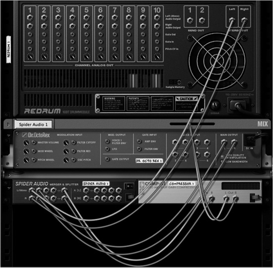
© Propellerhead Software AB.
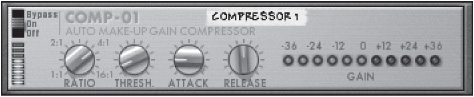
© Propellerhead Software AB.
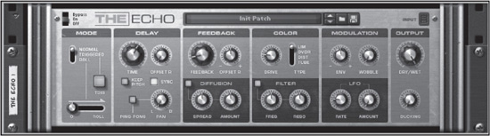
© Propellerhead Software AB.
The Feedback/Diffusion Section
Feedback allows you to control how long it takes for echoes to die out once they are triggered. At the same time, the Feedback knob increases the number of echoes heard. The higher you raise the knob, the more echoes you get. You can also use the Offset knob to modify where the feedback appears in your mix. Cranking the Offset setting causes the feedback stream to wander over to the right channel. Decreasing it causes the feedback coming from the echo to slowly move to the left. This capability can be very helpful for building soundscapes of echo feedback that travels the stereo spectrum. Diffusion is used for “smearing” your echoes. This, in a sense, makes the echoes seem much less intense, with the diffusion rounding off the attack and decay of each echo. The overall result is an echo that does not seem so manufactured; it’s more authentic.
The Color/Filter Section
A delay doesn’t always have to be a carbon copy or reproduction of the signal that runs through the delay/echo unit. Using the Color section of The Echo, you can introduce character and aggression to your echoes. The Color setting actually has four modes:
![]() Limiter: Limiter (“Lim”) mode pushes up the volume of even the lowest echo but does not cause the echo to peak, which would cause distortion. Use this mode to maintain a relatively clean signal with highly defined echoes, emulating the limiting that happens with tape saturation.
Limiter: Limiter (“Lim”) mode pushes up the volume of even the lowest echo but does not cause the echo to peak, which would cause distortion. Use this mode to maintain a relatively clean signal with highly defined echoes, emulating the limiting that happens with tape saturation.
![]() Overdrive: The rest of the modes are all about introducing distortion, including Overdrive (“Ovdr”) mode. This creates a distortion that affects largely boosts and distorts the higher frequencies.
Overdrive: The rest of the modes are all about introducing distortion, including Overdrive (“Ovdr”) mode. This creates a distortion that affects largely boosts and distorts the higher frequencies.
![]() Distortion: The Distortion (“Dist”) mode distorts and boosts the mid range and low end.
Distortion: The Distortion (“Dist”) mode distorts and boosts the mid range and low end.
![]() Tube: This resembles the classic tube-based amplifiers. Use this mode for a more “vintage” sound.
Tube: This resembles the classic tube-based amplifiers. Use this mode for a more “vintage” sound.
The Filter section is highly useful. One of the problems with echoing low-end and mid-range frequencies is that when you double the low end, you create “mud” in your mix. This eliminates the low-end dynamics and gives you a nasty wall of sound. Use the Filter settings to eliminate low frequencies in your echoes and maintain clarity in your mix.
The Modulation/LFO Section
The Modulation and LFO section can cause slight to serious pitching to your incoming signal. But why would you want that from a delay/echo device? In the case of the Envelope knob, labeled “Env,” you can create from subtle to drastic pitch bends in real time on your incoming signal. The Envelope knob bends the first note play, or first signal in, only once. As an example, the first note of a piano input will be bent once, and then the note will continue to play out bent, but no further bending will occur. It can be quite beautiful to have a touch of the Envelope setting engaged on guitar, as a matter of fact. This gives you a small chorus-style effect, which greatly fattens your guitar. The Wobble knob introduces a subtle pitch shift to your echoes that is meant to resemble the vintage tape echoes of the past. For the most part, this effect gives your echoes a distinct vintage or psychedelic feel. The Rate knob in the LFO subsection causes a linear bending of your signal similar to the Envelope modulation, except this is continuous bending, not just the initial signal. That means you will continue to hear pitch bending going up and down until the echo finally dies out. To hear the effect, you need to raise the Amount knob. The LFO, with minimal Amount and Rate values, is very subtle and introduces an all-encompassing chorus effect. Alternatively, you can use drastic rate levels to create everything from alien- to distortion-type effects.
The Output Section
The Output section contains only two knobs: Dry/Wet and Ducking. The Dry/Wet knob, as with all other effects in this chapter, allows you to increase the wetness of the delayed/echoing signal. But you’ll discover that The Echo has many more uses than all the other effects. In fact, with Roll mode (see the following exercise), you actually need to turn the Dry/Wet knob all the way up. This is a setting you won’t normally find recommended with a delay/echo device! To sum it up: For regular usage, keep the Dry/Wet knob in the middle; turn it to 10 o’clock for standard echo/delay; and turn it all the way up for roll- and DJ-style effects. Ducking causes The Echo to lower the echo effect every time it receives an incoming signal from the source device. For example, if I strum my guitar, The Echo immediately lowers the delayed signal. One problem with echo/delay effects is that you can lose your original source signal in the myriad echoes being produced. By using the Ducking knob, you can retain definition of your incoming signal while getting some really great delayed ambience in the background.
The Mode Section
Use the Mode section to change the overall functionality of The Echo. In Normal mode, The Echo functions for the most part like every other delay device in Reason. (Because the rest of this chapter explains in depth how echo/delay devices work, I won’t go into any depth on it here.) The Triggered and Roll settings defy how any echo/delay devices work in this chapter, so I’ll spend the rest of this section addressing these modes.
Triggered mode causes The Echo to stop producing its echo effect unless you click the Trig button. The longer you hold down the Trig button, the longer it will create echoes for your incoming signal. This capability is useful when you want to echo only one word from a verse or chorus or you want to echo only the snare drum during a loop. You can get very creative with this feature! What’s interesting is that clicking the Trig button does not kill the decay of the echo effect. It still decays gradually, according to the level of your Feedback knob.
Roll mode is my absolute favorite feature of The Echo. When you’re in Roll mode, you cannot hear any delay unless you raise the Roll slider. I encourage you to turn the Dry/Wet knob in the Output section all the way up when doing this. Raising the Roll slider creates incredible shifts in timing, which utterly depend on the level of the Time and Feedback settings. Because I feel this is something you experience better than read about, let’s do a quick exercise.
Using Roll Mode with The Echo
Let’s use Roll mode with The Echo:
1. Create a Dr. Octo Rex and then create an instance of The Echo (see Figure 10.29).

© Propellerhead Software AB.
2. Load any drum loop you want into the Dr. Octo Rex. I used the 2+4 Nailed loop. To find it, launch the Reason Factory Sound Bank, open the Dr. Octo Rex Patches folder, and then open the Acoustic Drums folder (see Figure 10.30).
3. If The Echo unit does not say Init Patch, right-click on the unit and select Initialize Patch (see Figure 10.31). This puts the unit in a zeroed, blank state with no real settings.
4. Put your The Echo unit into Roll mode (see Figure 10.32).
5. Click the Run button to start your Dr. Octo Rex. As you do, you’ll notice that the loop seemingly has no effect on it from The Echo. This is as it should be. While this is taking place, move the Roll slider to the right (see Figure 10.33). You’ll notice a significant stutter. Try this several times while adjusting the Time knob.
After you run through this exercise, I’m sure you can see the implications for the power of this feature. With lower Time settings, you can introduce stutters. With higher Time settings, you can introduce very natural change-ups to your drum loops, making them something other than a repeat of the same thing over and over again!
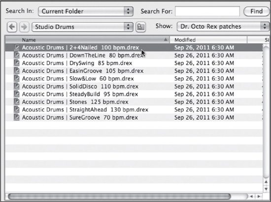
© Propellerhead Software AB.

© Propellerhead Software AB.

© Propellerhead Software AB.
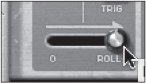
© Propellerhead Software AB.
The Alligator
Of every Reason effect, the Alligator offers the most instant gratification. Propellerhead’s name for the Alligator, Triple Filtered Gate, does not really give you the best description of what it does. Really, though, there’s no other title I can think of that comes close other than “Chews up everything that you put into it and spits out something else.” Well, that’s what an alligator would do, right?
The Alligator depends on three gates that you can trigger (shown in Figure 10.34). They make up the core of its magic. Sound is fed into all three gates simultaneously, but no sound passes through the gates until they open.

© Propellerhead Software AB.
How do you open the gates? Well, there are many ways. The easiest is the pattern generator, shown in Figure 10.35. Each pattern number is a different order and set of timings from the last. The greater the number, the more interesting and weird some of the patterns get.

© Propellerhead Software AB.
You can use the Resolution knob (see Figure 10.36) to slow down or increase the speed of your pattern in the allotted note values in relation to your host tempo. Even though your actual song tempo may be quite high, it’s sometimes good to have patterns playing in slower resolutions, like 1/8 notes. This creates a greater dimension in your song.

© Propellerhead Software AB.
The Shift knob (see Figure 10.37) works in increments of 1/16 notes. Each shift forward or backward takes you forward or back one step in timing. Use this knob to offset your pattern timing to give each pattern a new feel. Because shifting forward or backward moves the place where the Alligator pattern starts, shifting can almost make it sound as though you have a new pattern altogether. If you combine Shift and Resolution movements, there are tons of possible patterns.
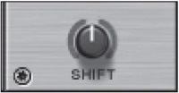
© Propellerhead Software AB.
If you’re doing a style of rhythm in your song that has a more relaxed beat, like house or hip hop, you may want to use the Shuffle button (see Figure 10.38). When Shuffle is enabled, it’s tied to the Global Shuffle found in the ReGroove Mixer.

© Propellerhead Software AB.
NOTE: On an initialized SubTractor that is running through the Alligator, sequence some half, whole, and quarter notes. After you play with this for a minute, try adjusting the Pattern number, the Shift knob, and the Resolution setting. You’ll be amazed at what the Alligator can do with even its most basic settings!
Alligator Envelopes
Now that you know how to trigger the gates of the Alligator using the built-in pattern generator, let’s talk about controlling how the gates open and close. Currently, when you run the Alligator with the Pattern settings, the sound allowed through is longer and more open. What if you could cause the sound to pass through in smaller increments, making your incoming signal sound more choppy and tight? There are a couple of ways of doing this:
![]() The Amplitude Envelope settings
The Amplitude Envelope settings
![]() The Filter Envelope settings
The Filter Envelope settings
The Amplitude Envelope Settings
The Amplitude Envelope settings, labeled “Amp Env” (see Figure 10.39), consist of three knobs: A (Attack), D (Decay), and R (Release). Adjusting these knobs affects how the gates open and close when they are triggered.
© Propellerhead Software AB.
If you adjust the Attack (A) knob, the amp envelope will cause the gates to open a little more slowly, cutting off the beginning part of the signal. This makes outgoing bursts from the gates seem a little more hushed and less harsh.
When adjusting the Decay (D) knob, you can clamp down on how long the gates stay open. For example, sustained notes going through will sound much choppier if you lower the decay time. If the decay time is up all the way, the sounds coming through the gates will play out much longer and fluidly. Use lower decay settings to create choppier drum loop effects or tight melodic patterns.
The Release (R) knob in low amounts causes the Alligator gates to stay open just a little bit after they’ve been triggered. In higher amounts, the gates will lazily close, making it sound as though a sound is slowly fading out like a bell has been struck. This effect is useful for sustained synth notes because it causes your sustained notes to sound more like piano or bell parts that gradually fade out over time. Higher sustain can also be good for allowing sections of drums to fade out without cutting off abruptly. Lower the release time to simulate abrupt, choppy rhythms and grooves.
The Filter Envelope Settings
The Filter Envelope settings, labeled “Filter Env” (see Figure 10.40), sculpt how sounds pass through the gates, but very differently. Whereas the amp envelope controls how the gates actually open and close through volume, the filter envelope controls how the filters open and close.

© Propellerhead Software AB.
By default, the filter envelope does nothing if you manipulate the A, D, and R knobs. You need to enable the filter envelope knobs on one or each of the gates for this to work (see Figure 10.41).

© Propellerhead Software AB.
Adjusting the filter envelope knob on a gate causes the filter envelope to have a lesser or greater effect in how the filter opens and closes in relation to the filter envelope settings. For example, if the Attack (A) knob is raised, the filter will appear to sweep at the beginning of the note. The faster the sweep depends on the amount of attack you’ve assigned.
You can turn the filter envelope amount in the opposite direction as well, toward the negative polarity. When you do this, the filter envelope settings work in reverse. For example, if Attack (A) is raised and the filter is reversed on the low pass–enabled gate, the filter will seem to close up when the gate is opening instead of fading in. Reversing polarity can be very helpful when you are using the high-pass or band-pass filters because the higher frequencies almost need to be reversed to actually hear the signals in higher frequency registers.
Alligator Filters and Channel Options
We’ve talked about the filter envelope, but strangely, we haven’t talked about the filters themselves! Let’s amend this. The filters on each gate are what ultimately give character and differentiation between each gate triggered by coloring each gate with shades of frequencies (see Figure 10.42).

© Propellerhead Software AB.
Because of the dedicated filters for each gate, you can almost consider each gate an instrument in its own right. For example, the high-pass gate can be considered a module that outputs tinnier, upper frequency–style sounds. If you run a drum loop through the Alligator and all gates are running together in pattern, the patterns distributed from the high-pass filter (see Figure 10.43) will greatly resemble a hi-hat. This depends on the Frequency (labeled “Freq”) and Resonance (labeled “Res”) settings, of course. To make this gate more audible when using the filter envelope, try reversing the polarity.

© Propellerhead Software AB.
The band-pass filter (shown in Figure 10.44) outputs mid range–style patterns. Think of this filter as outputting instruments along the lines of toms and snares. However, increasing the frequency on this gate can make it behave like the high pass, and lowering the frequency will make it behave like the low pass.

© Propellerhead Software AB.
You can think of the low-pass filter on gate 3 for bass and kick drum–type patterns. Personally, I use this one more than any other. And, yes, through the Volume knobs, you can disable or lower the volume of each filter (see Figure 10.45).
Because the low-pass-filtered gate is designed to enhance or boost low signals, especially with use of the filter envelope, I suggest keeping it center panned as opposed to panning left or right. You can pan each filter through use of the Pan knobs located on each gate (see Figure 10.46).
Through use of the Pan knobs, individual gate volumes, and filters, one single-source input going through the Alligator literally gets spit out as three different parts. This makes it much easier to populate a sparse arrangement, making something that is very simple into something much more complex.

© Propellerhead Software AB.

© Propellerhead Software AB.
TIP: Did you know you can disable the filters on each of the gates? Using the small On buttons (see Figure 10.47) at the beginning of each gate channel strip, you can turn filter activity off completely. Use this On/Off function when you don’t need filtering but want standard gates.

© Propellerhead Software AB.
Alligator Effects
Besides being an effect that essentially turns one signal into several instruments, the Alligator is also a multi-effects processor. You get a Phaser effect and a Delay effect that can be routed to each gate in varying amounts through the Gate Mix section (see Figure 10.48).
© Propellerhead Software AB.
These individual knobs afford you the ability to have, for example, some delay on the high-pass gate, while at the same time giving no delay to the low-pass channel. The behaviors of each of the effects can be modified below in their labeled locations. Let’s talk about the controls of each device.
The Delay is a simple device that produces echoes on its own, similar to The Echo, discussed previously in this chapter. Keep in mind that this is a much simpler version of The Echo, RV7000, and resembles mostly the DDL-1 Digital Delay in Reason. What’s helpful about having the Delay built into the Alligator is that it’s just that much less patching you have to do, and as I mentioned earlier, you’re much closer to instant gratification. The Delay falls short of having many of the additional features the previously listed effects devices have, but it can be synced to the Reason host tempo and can be panned, which is encouraged when using all the Alligator’s gates because this frees up space in your mix.
The Phaser allows you to add a thickness to your gates when the rate is turned up higher. When it’s lower, you can get very subtle sweeping psychedelic effects, which can be made much more severe using the Feedback knob.
Another brilliant effect feature added to the Alligator is the LFO, shown in Figure 10.49. LFO modulation can be introduced on each of the filters, where they can add subtle to extreme filter modulation. Like the Delay, the LFO can be synced through use of the Sync button. And, as with the filter envelope, subtle to extreme amounts can be added in positive to negative polarities using the LFO Amount knobs on each gate channel in the Filter section (see Figure 10.50).

© Propellerhead Software AB.

© Propellerhead Software AB.
Believe it or not, the Alligator also has distortion features available. Although there’s no real control over the type of distortion, the Drive knobs available on all gate channels can be used to add some grit and aggression to each of your gates (see Figure 10.51). When they are used in conjunction with the filter envelope with massive filter sweeps, you can easily emulate old synths like the TB-303.

© Propellerhead Software AB.
The Dry Section
You may want to pay a small bit of attention to the Dry section. The Volume knob in this section allows you to introduce the original source signal unaltered into your Alligator mix (see Figure 10.52). This can be handy when you want to double the drums via the Alligator while keeping the original drum mix (or loop) or you want to use the sustained signal (like a pad) along with the Alligator’s gated parts. The latter is an excellent strategy when used with automation because you can bring in the sustained notes in certain parts of the song and then keep the gated parts going the rest of the time. It’s like having a lead with three other synth parts, all generated from one synth or sampler! And because you can pan the dry signal, you can even keep your incoming signal in certain sections of your stereo field as opposed to always being in the center.

© Propellerhead Software AB.
Pulveriser
The Pulveriser (see Figure 10.53) introduces some of the most severe compression I’ve ever heard in any software package mixed with modulation, distortion, and a filter. It’s even capable of using the incoming signal to modulate selectable parts of the Pulveriser device internally. In short, the Pulveriser is another seemingly simple device with a few far-from-obvious tricks up its sleeve. Let’s start with the basics.

© Propellerhead Software AB.
The Pulveriser as a Compressor
Setting up the Pulveriser as a compressor is easy. It’s simply a matter of creating the device and raising the Squash knob until you get the desired effect. Unlike most compressor knobs, the Pulveriser’s Squash knob controls not only the compression ratio, but also the threshold and make-up gain all in one shot (see Figure 10.54).

© Propellerhead Software AB.
It’s easy to mistake the Follower section of the Pulveriser, with its Threshold knob, as what you would use to set your compression threshold and adjust your attack and release. This section actually does something entirely different, though! In fact, the Release knob is the only knob you will find on a conventional compressor that is separate from the Squash knob. This knob controls how fast the compressor opens up after it has been closed down. Setting the Release low with a high Squash setting causes you to get that pumping sound that is so desirable for drum loops, basses, kicks, and so on.
The Pulveriser for Distortion
Once you’ve added compression via the Squash knob and set your release, you might consider adding some dirt using the Dirt knob (see Figure 10.55). When you raise the Dirt value, you raise the Pulveriser’s built-in distortion. You cannot modify the type of distortion given here, but it’s really good distortion, and it can get very severe as you raise it higher and higher.

© Propellerhead Software AB.
When you add the Routing switch into the mix (see Figure 10.56), you get even greater possibilities. By default, the compressed signal (Squash) goes through the distortion (Dirt) and then the filter. When you adjust the Routing switch, though, you can have the filter go through the compressor (Squash) and then the distortion (Dirt). This is really helpful, because in the first mode, you have the ability to filter a compressed signal, and in the second mode, you are ultimately compressing and distorting a filtered signal.

© Propellerhead Software AB.
NOTE: Try running a drum loop through a Pulveriser. On the Pulveriser, add significant amounts of Squash with a very low release. Lower the Filter Frequency setting to midway and raise the Peak knob. Next, adjust the Routing switch at the bottom of the Pulveriser and listen to the difference! While the drums are playing, adjust the Filter and Peak knobs for extra fun.
The Tone knob begins our descent into the filtering aspect of the Pulveriser. The Tone knob is a dedicated low-pass filter that clips off more and more of the high end the more you lower it. If the Tone knob is all the way up (5 o’clock), no filtering is taking place. As we get into the next section, realize that you actually get two filters on this crazy device!
Pulveriser Filter Modulation
The Pulveriser supplies a Filter section (see Figure 10.57) that is similar to many other devices in Reason. You get the familiar notch, low pass, band pass, high pass, and comb filters found in devices like Thor, Malström, and Kong.

© Propellerhead Software AB.
Of course, this wouldn’t be a Propellerhead device if it didn’t have a way to modulate the filter. This is where the device becomes unique: with the Follower section. Remember when I mentioned that the Threshold knob in the Follower section of the Pulveriser has nothing to do with the compression settings? Well, let’s talk about what it does! On its own, with no additional settings, the Follower (see Figure 10.58) is just a red light that reacts more and more intensely the lower you take the knob. As with all threshold functions, the lower you bring down the threshold, the more reactive the result is. The attack and release determine how quickly or slowly the Follower opens, closes, and shuts down.

© Propellerhead Software AB.
The Follower becomes much more powerful when it’s assigned to modulate specific parameters of the other functions on the device, like the filter, using the small modulation knobs all over the Pulveriser. Say you have a synth bass coming in playing 1/8 notes. You can set the Pulveriser’s Follower Threshold setting to sit at a point where the light blinks steadily with each hit of bass synth. Then you can route the Follower to Frequency knob (see Figure 10.59) to send modulation to the filter. Each time the bass synth plays, the filter will open!

© Propellerhead Software AB.
There are several modulation paths from the Follower to other sections of the Pulveriser. This is also true for the Tremor device in the Pulveriser.
Tremor
Tremor (shown in Figure 10.60) is a syncable LFO unit capable of controlling the filter cutoff frequency and output level of the Pulveriser. This makes the Pulveriser a kind of cousin to the Alligator because you also can use the Pulveriser for gating effects. The main difference is that the Pulveriser relies on a single LFO to modulate each effect’s output or filter.

© Propellerhead Software AB.
Tremor also features a very cool Spread function that modulates the phase and panning of the incoming signal. This is cool for opening up a drum loop or another instrument that is taking up a lot of space in your mix!
Using the modulation knobs on either side of Tremor (see Figure 10.61), you can decide whether you want to modulate the output of the Pulveriser or the frequency of the Pulveriser’s filters. Doing this can cause the signals to rhythmically blend with other thick signals by cutting the frequency when other parts are introduced. You can even use higher frequency rates to get severe distortion.
© Propellerhead Software AB.
Neptune
Not all of us have perfect pitch…myself included. Although I’m not a bad singer, when you go back and listen to recordings of my performance, you’ll hear certain sections when I get out of tune. Because Reason allows for audio recording, it’s of great importance that I tell you how to get yourself back in tune—with Neptune.
It’s important to start off by saying that Neptune (see Figure 10.62) can sound as natural or as synthetic as you want it to sound. In the past 15 years, there has been no end to misuse of pitch-correction devices and software to create voice effects that sound almost human. If this is your goal, Neptune will meet you there, too.
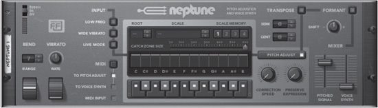
© Propellerhead Software AB.
What’s even more astounding about Neptune is that it also goes beyond regular pitch correction and provides a powerful harmonization unit that can be used in multiple ways. Need backup harmonies? Neptune has you covered. Need a small barbershop quartet? Neptune’s still got your back.
Neptune for Pitch Correction
Pitch correction actually sounds much more daunting than it really is. For the most part, you just choose a scale and go. It’s in this middle section of Neptune, the Pitch Adjust section, that most of your work will actually take place (see Figure 10.63).
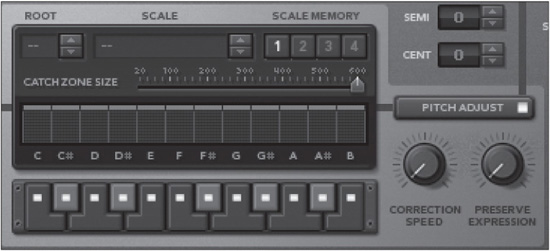
© Propellerhead Software AB.
If you know what scale you’re singing in, just click the Scale drop-down menu (see Figure 10.64) and choose the appropriate scale. Next, set the root key you’re singing in (see Figure 10.65).
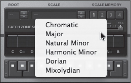
© Propellerhead Software AB.
At this point, it’s safe to listen and see how your pitch-correction settings are working. If you discover a certain key being hit that you don’t like, simply select the key in the Pitch Adjust section (see Figure 10.66). Clicking the key disables it as a possible note, leaving only the enabled notes as possibilities as your recording signal goes through the unit.
Now you’ll need to decide how natural you want your pitch correction to be. With the Correction Speed knob set to the lowest possible setting (see Figure 10.67), Neptune slowly moves your pitch to the key’s right pitch. Pitch correction is almost unnoticeable in this mode. If you move the Correction Speed knob to 12 o’clock, pitch correction is noticeable but very natural. If you boost it all the way up, you get robot voice.
If you have vibrato in your vocal recordings that you want to keep, you can use the Preserve Expression knob. The more you turn this knob up, the more original vibrato you will hear from the recording.
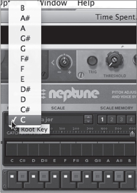
© Propellerhead Software AB.
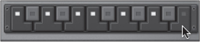
© Propellerhead Software AB.

© Propellerhead Software AB.
Controlling Neptune Through MIDI
One of the coolest things about Neptune is the ability to control your vocal’s pitch with your MIDI keyboard! To set this ability, right-click on your Neptune unit and select Create Track for Neptune, as shown in Figure 10.68.
After creating this track, you will notice that there is a keyboard present under the Neptune icon in the sequencer (see Figure 10.69). That means you have MIDI keyboard control over this device.
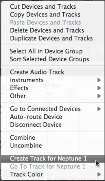
© Propellerhead Software AB.

© Propellerhead Software AB.

© Propellerhead Software AB.
Run your recorded audio by starting the sequencer and playing your MIDI keyboard. Your keyboard now controls the pitch of your voice. If you’d like to keep your original voice recording as the main part but add in some harmonies that you control by keyboard, switch to Voice Synth Mode, as shown in Figure 10.70.
Neptune is a powerful device for vocals, but it can also be used for monophonic instruments such as violin and bass. Experiment!
Audiomatic
Another effects device that you may want to familiarize yourself with is the Audiomatic Retro Transformer. (That’s a mouthful, huh?) This device is included along with the purchase of Reason 7, and is a lot like Instagram for audio. How could this be? Read on!
If you pull up an Audiomatic, the first thing you’ll notice will be the 16 orange buttons that adorn the front panel. These buttons trigger audio effects that can transform the overall “feel” of your sound greatly or subtly. Every effect works slightly differently. Some effects squash your audio, some add some high end, some widen the sound, and so on. It just depends on which effect you choose!
Audiomatic is intended to be used along with another extremely cool feature that has been added in Reason 7 known as parallel mixer channels. Parallel mixer channels, also known as parallel compression, have become a favorite trick for many producers as they afford you the ability to quickly and easily get a bigger sound for drums, basses, voice, etc., by doubling a source signal through several channels. Each of these copied channels can be used to add slightly different characteristics to your source signal. For example, suppose your SubTractor part is dry (or lacking any form of effect). Your second parallel channel, which is the exact same signal as your original SubTractor part, may have some distortion on it, with the EQ doing a HP filter just to add body to the upper parts of the bass while killing the lower frequencies. A third parallel channel might go through an LP filter with a 250 Hz boost to give a little body. When all these channels play back at once, you get a much bigger sound, because the original source, the SubTractor, is being doubled three times. But, each version has different tonal qualities.
Let’s try seeing this in action with Audiomatic!
1. Create a Dr. Octo Rex. Then click the Browse Patch button and go to the Dr. Octo Rex Patches folder in the Reason Factory Sound Bank. In this directory, choose the Guitar Loops folder, the Electric Rhythm Guitar folder, and the Kirk Riffs Key Of A file (see Figure 10.71). This set of loops will be great because electric guitar is a perfect instrument for doubling and distorting.
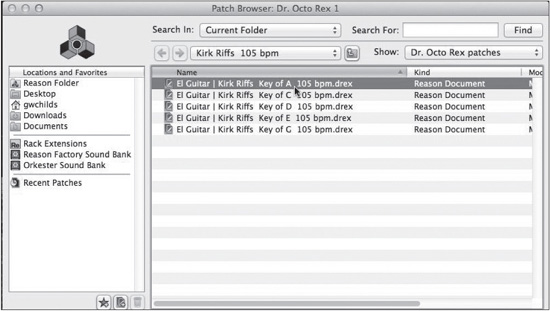
© Propellerhead Software AB.
2. Now that you have a fully loaded Dr. Octo Rex, add in a parallel channel. To do this, right-click on the Mix device in your rack that is labeled for your recently created Dr. Octo Rex and choose Create Parallel Channel (see Figure 10.72). When you do, a second Mix device will appear. This device will be labeled starting off with a “P1” in its title, which, of course, stands for “parallel channel 1.”
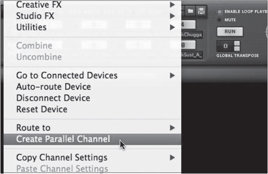
© Propellerhead Software AB.
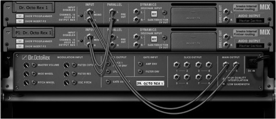
© Propellerhead Software AB.
3. The new parallel mix channel looks like it’s been set up as a regular old mix channel. But, if you were to open up this device, turn it around, and look at the routing from the original mix channel to the new parallel channel, you’d notice something different. The original mix channel device is sending signal to the P1 mix channel through the parallel output. No new devices have been created. It’s still just the good old Dr. Octo Rex. (See Figure 10.73.)
4. Because these channels are exactly the same, sonically speaking, now would be a good time to start making them sound a little different so they aren’t exact copies. Also, as mentioned, changing the parallel channel’s sonic qualities makes the instrument sound bigger. On the parallel channel, create an Audiomatic device. To do so, right-click the P1 channel, choose Creative FX, and select Audiomatic Retro Transformer (see Figure 10.74).
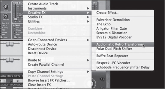
© Propellerhead Software AB.
5. If you play the Dr. Octo Rex device now, you’ll notice that there is already a difference between the original mix channel, and the parallel channel. The Audiomatic Retro Transformer is already in effect. You can hear the difference by clicking the Solo buttons on the mix channels. To hear a big difference, click the Cracked button on the Audiomatic device (see Figure 10.75). This adds a nice layer of distortion to the parallel channel and instantly makes the guitar rock. You can also raise the Gain knob on the Audiomatic device to overdrive the signal a little. And, you can use the Transform knob to modify the effect in new and strange ways. You’ll notice that if you turn the Transform knob up when in the Cracked mode, the signal gets thinner. Because you’re doubling your signal, it might be nice to keep the signal a little thinner so that both tracks can work together nicely.

© Propellerhead Software AB.
6. Because you have the higher registers taken care of with your first parallel channel, it might be nice to add some body in the mid frequencies. Right-click on the parallel mix device and choose Create Parallel Channel (see Figure 10.76). (You always create an additional parallel channel from the last parallel device added in the chain. If you try to add another parallel channel from the original mix device, it will be grayed out!)
7. On the second parallel channel, change it up a bit. For this channel, add a Scream device. To do so, right-click on the P2: Dr. Octo Rex, choose Creative FX, and select Scream. To ensure more mid-range qualities for this channel, enable the Cut function on the Scream device. Then increase the Mid slider while lowering the Low and Hi sliders (see Figure 10.77).
8. Now that the mid range has been boosted, choose a distortion type that will blend well with what’s already going through Audiomatic. In Scream, select the Distortion damage type selection. Then try dialing in your sound with the P1 and P2 knobs. Also, try using the mixer levels and Pan knobs for each channel to create a good mix between all the different channels running this one guitar loop.
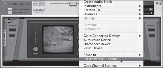
© Propellerhead Software AB.

© Propellerhead Software AB.
That’s really all there is to parallel channels. And, as you can see, it is easy to use the Audiomatic Retro Transformer. But, don’t think to stop there with Audiomatic and parallel channels. With regard to Audiomatic on its own, try using it as a mastering effect on your master out. It gives an amazing feel to a final mix. For parallel channels, try doubling vocals and doubling synths (or tripling, or quadrupling). When you have seven channels of the same thing, try sending them all to an output bus, the way you did in Chapter 3, “Recording and Effects.” This is a great way to group all of your channels and keep the mix intact under one final fader.
Moving On
Judging by the length of this chapter, the number of possibilities with the effects in Reason should keep you happy and occupied for a long, long time to come. In the next chapter, you’ll start working with an amazing device that is designed to combine other devices—get ready for the Combinator!