
11 The Combinator: Close-Up
IF THERE WERE A SINGLE RACK DEVICE CREATED FOR REASON THAT ADDS MORE POWER TO THE APPLICATION THAN ANY OTHER, the Combinator would have to be it! In short, the Combinator (see Figure 11.1) allows you to combine multiple devices (all controllable by a single sequencer track), route them any way you like, and save the entire setup as a single patch. As you read this chapter, you will discover how this seemingly simple concept offers limitless possibilities.

© Propellerhead Software AB.
Keep ’Em Combinated
Reason includes numerous Combinator presets, which appear as Combi (.cmb) patches in the Factory Sound Bank. Becoming familiar with these presets can help you determine which ones will be useful to you as you work on your projects, and should also provide inspiration and direction in creating your own Combi patches.
Combi patches can be divided into two basic types:
![]() Effect Combis: As you might guess, effect Combis are used to process sound rather than to generate sound as an instrument would. The MClass Mastering Suite Combi is an effect Combi.
Effect Combis: As you might guess, effect Combis are used to process sound rather than to generate sound as an instrument would. The MClass Mastering Suite Combi is an effect Combi.
![]() Instrument Combis: These Combis include sound-generating instrument devices, such as SubTractor, Thor, NN-XT, or Redrum, and can also contain effect devices. The only upper limits to the fatness of layered sounds that can be created in this way would be what your computer and your brain can handle!
Instrument Combis: These Combis include sound-generating instrument devices, such as SubTractor, Thor, NN-XT, or Redrum, and can also contain effect devices. The only upper limits to the fatness of layered sounds that can be created in this way would be what your computer and your brain can handle!
By the way, remember that the Mix Channel and Audio Track devices in Reason are similar to the Combinator and have much of the same functionality, including the ability to load effect Combis (but not instrument Combis)!
A Guided Tour of the Combinator
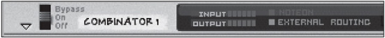
Open a new document and create a Combinator. Take a look at the topmost panel of the Combinator (the part that still shows when the Combinator is folded) and note that, in addition to the usual Select/Browse/Save patch buttons, there is also a Bypass/On/Off switch like that found on Reason effect devices. Also included are input/output level meters, a MIDI note-on indicator, and an External Routing indicator, which lights up if you route audio or modulation output from any Combinator device to another device outside the Combinator. The External Routing indicator (see Figure 11.2) can be considered a warning indicator because it alerts you to the presence of external connections, which will not be saved with the Combi patch.
© Propellerhead Software AB.
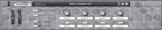
The Controller Panel
The Combinator’s Controller Panel consists of the following elements:
![]() Pitch wheel: This sends pitch bend info to all instrument devices contained in a Combi. The bend range is set individually in each instrument device’s Range field.
Pitch wheel: This sends pitch bend info to all instrument devices contained in a Combi. The bend range is set individually in each instrument device’s Range field.
![]() Mod wheel: This sends modulation data to all instrument devices contained in a Combi. The effect of this modulation data is determined by the individual mod wheel assignments made in each instrument device. The Combinator mod wheel can also be custom routed to control other knobs, sliders, and so on, in addition to the instrument modulation wheels to which it is automatically routed.
Mod wheel: This sends modulation data to all instrument devices contained in a Combi. The effect of this modulation data is determined by the individual mod wheel assignments made in each instrument device. The Combinator mod wheel can also be custom routed to control other knobs, sliders, and so on, in addition to the instrument modulation wheels to which it is automatically routed.
![]() Run Pattern Devices: This starts or stops all pattern devices in a Combi, such as a Matrix sequence or a Dr. Octo Rex pattern. This button is automatically activated when you click Play on the Transport panel.
Run Pattern Devices: This starts or stops all pattern devices in a Combi, such as a Matrix sequence or a Dr. Octo Rex pattern. This button is automatically activated when you click Play on the Transport panel.
![]() Bypass All FX: This bypasses all effect devices included in a Combi, switching all insert effects to Bypass mode and switching off all effects connected as send effects to a mixer device. This button does not affect effects already bypassed or turned off.
Bypass All FX: This bypasses all effect devices included in a Combi, switching all insert effects to Bypass mode and switching off all effects connected as send effects to a mixer device. This button does not affect effects already bypassed or turned off.
![]() Show Programmer: This shows or hides the Programmer panel.
Show Programmer: This shows or hides the Programmer panel.
![]() Show Devices: This shows or hides all devices included in a Combi.
Show Devices: This shows or hides all devices included in a Combi.
![]() Rotary knobs: These can be assigned to control parameters in any devices included in a Combi. Rotary knob control assignments are made in the Modulation Routing section of the Programmer panel. You can customize Rotary knob labels by clicking on the label and typing in a name.
Rotary knobs: These can be assigned to control parameters in any devices included in a Combi. Rotary knob control assignments are made in the Modulation Routing section of the Programmer panel. You can customize Rotary knob labels by clicking on the label and typing in a name.
![]() Button controls: These can be assigned to control any button-controlled parameters in devices included in a Combi. Note that the Button controls switch between only two values, so if the device parameter you are controlling has more than two possible values (like an On/Off/Bypass switch or an LFO Waveform button), a Combinator Button control will toggle between only two of those values. As with the Rotary knobs, you can assign useful names to your Button controls by clicking on the labels and typing away.
Button controls: These can be assigned to control any button-controlled parameters in devices included in a Combi. Note that the Button controls switch between only two values, so if the device parameter you are controlling has more than two possible values (like an On/Off/Bypass switch or an LFO Waveform button), a Combinator Button control will toggle between only two of those values. As with the Rotary knobs, you can assign useful names to your Button controls by clicking on the labels and typing away.
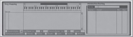
The Programmer
Now let’s click the Show Programmer button and dive into the pretty blue screen, which is really the nerve center of your Combinator. The Programmer may look slightly daunting at first, but it is actually rather straightforward and not at all difficult to master (see Figure 11.3). It controls the following five areas of functionality:
© Propellerhead Software AB.
![]() Key Range: This controls the lowest and highest note that will trigger any selected instrument device in the Combinator. This parameter cannot be adjusted unless Receive Notes is active for the selected instrument device.
Key Range: This controls the lowest and highest note that will trigger any selected instrument device in the Combinator. This parameter cannot be adjusted unless Receive Notes is active for the selected instrument device.
![]() Velocity Range: This controls the lowest and highest velocity that will trigger any selected instrument device in the Combinator. As with the Key Range, the Velocity Range cannot be adjusted unless Receive Notes is active for the selected instrument device.
Velocity Range: This controls the lowest and highest velocity that will trigger any selected instrument device in the Combinator. As with the Key Range, the Velocity Range cannot be adjusted unless Receive Notes is active for the selected instrument device.
![]() Transpose: This controls the pitch of a selected device in a Combi patch. The range is +/−3 octaves.
Transpose: This controls the pitch of a selected device in a Combi patch. The range is +/−3 octaves.
![]() Performance Controllers: This indicates which controller messages (pitch bend, modulation, and so on) received by the Combinator are passed along to the combined devices. For example, if you have a SubTractor in your Combi patch and the Pitch and Modulation controllers are selected, whenever you use those controllers via the Combinator, the same messages will be sent along to the combined device. In other words, everything is linked up and will work in combination with each other.
Performance Controllers: This indicates which controller messages (pitch bend, modulation, and so on) received by the Combinator are passed along to the combined devices. For example, if you have a SubTractor in your Combi patch and the Pitch and Modulation controllers are selected, whenever you use those controllers via the Combinator, the same messages will be sent along to the combined device. In other words, everything is linked up and will work in combination with each other.
![]() Modulation Routing: This assigns any parameters of the selected device in the Combinator to any of the virtual Rotary or Button controls on the Combinator’s Controller panel. Unlike the Key Range and Velocity Range sections of the Programmer, the Modulation Routing section can control non-instrument devices (such as effects) as well as instrument devices like the NN-XT or the SubTractor.
Modulation Routing: This assigns any parameters of the selected device in the Combinator to any of the virtual Rotary or Button controls on the Combinator’s Controller panel. Unlike the Key Range and Velocity Range sections of the Programmer, the Modulation Routing section can control non-instrument devices (such as effects) as well as instrument devices like the NN-XT or the SubTractor.
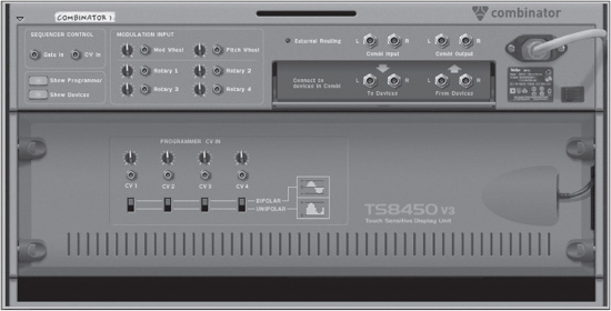
Combinator Routing
Make sure that Show Devices is enabled. Then press the Tab key to flip your Rack screen around and take a look at the back of the Combinator (see Figure 11.4).
© Propellerhead Software AB.
Audio Connections
The audio connections on the back of the Combinator are used to send audio to the Mix Channels as well as to receive it! This is also the place where devices within the Combinator connect so that they can be heard externally.
![]() Combi Input L/R: These are the inputs for the Combinator, used for effect Combis. In a mastering Combi, you would likely have the outputs of your main reMix plugged into these inputs.
Combi Input L/R: These are the inputs for the Combinator, used for effect Combis. In a mastering Combi, you would likely have the outputs of your main reMix plugged into these inputs.
![]() Combi Output L/R: These connect with any device outside the Combinator, usually a mixer or (in the case of a mastering Combi) the Reason hardware interface.
Combi Output L/R: These connect with any device outside the Combinator, usually a mixer or (in the case of a mastering Combi) the Reason hardware interface.
![]() To Devices L/R: These connect to the input of any device in the Combi. To Devices L/R is internally routed to Combi Input L/R.
To Devices L/R: These connect to the input of any device in the Combi. To Devices L/R is internally routed to Combi Input L/R.
![]() From Devices L/R: These connect to the output of a device (the last in a chain of devices or a mixer) in a Combi. From Devices L/R is internally routed to Combi Output L/R.
From Devices L/R: These connect to the output of a device (the last in a chain of devices or a mixer) in a Combi. From Devices L/R is internally routed to Combi Output L/R.
CV Connections
Control voltages within Reason are an amazing way to make the virtual devices go above and beyond. The Combinator is no exception!
![]() Gate In: This allows the Combinator to receive Note On, Note Off, and Velocity information from the Gate CV output of another device, typically a Matrix, a Redrum, or an RPG-8 Monophonic Arpeggiator.
Gate In: This allows the Combinator to receive Note On, Note Off, and Velocity information from the Gate CV output of another device, typically a Matrix, a Redrum, or an RPG-8 Monophonic Arpeggiator.
![]() CV In: This allows the Combinator to receive Note Pitch information from another device, typically from the Note CV output of a Matrix or RPG-8.
CV In: This allows the Combinator to receive Note Pitch information from another device, typically from the Note CV output of a Matrix or RPG-8.
![]() Modulation Inputs: This allows the mod wheel, pitch wheel, or any of the four Combinator Rotary controls to be modulated by CV.
Modulation Inputs: This allows the mod wheel, pitch wheel, or any of the four Combinator Rotary controls to be modulated by CV.
![]() Programmer CV Inputs: These inputs are used to route the CV output of any Reason device to a specific parameter of a device loaded in a Combi patch via the Programmer. For example, you can have the filter section of an instance of the SubTractor loaded in a Combi patch modulated via an instance of the Matrix.
Programmer CV Inputs: These inputs are used to route the CV output of any Reason device to a specific parameter of a device loaded in a Combi patch via the Programmer. For example, you can have the filter section of an instance of the SubTractor loaded in a Combi patch modulated via an instance of the Matrix.
Before you jump headlong into designing your first Combi patch, let’s take a moment to look at another Reason device designed for use with the Combinator: the microMIX 6:2 line mixer.
microMIX
Want to mix and route some devices in your Combinator, but you don’t need all the bells and whistles of reMix? Propellerhead has you covered. Although reMix can be used in Combinator patches, the microMIX line mixer was created specifically for mixing device outputs in a Combi in cases where the more advanced capabilities of reMix may not be required. Although microMIX is tailor-made for use with the Combinator, it can, of course, be used for other applications anywhere in your Reason song, such as submixing large drum kits or for adding a few extra channels when your main reMix is filling up. It should be noted that in the Rack screen, this device is labeled “microMIX,” but in the Create menu, it is referred to simply as “Line Mixer 6:2.” Go ahead and create an instance of this bad boy so you can follow along.
Each of the six channels in a microMIX (see Figure 11.5) includes an output Level control, a Pan knob (which can be controlled externally via CV), a Mute button, a Solo button, one Auxiliary Send Level knob (labeled “Aux”), a customizable channel label, as well as a three-segment output level meter. Rounding out the front panel is the Master knob, which controls the summed output level of all the channels in the microMIX. Finally, you have the Auxiliary Return Level knob, labeled “Aux Return,” which controls the level of the signal coming back from whatever effect device has been connected to the Auxiliary Send output of the microMIX.

© Propellerhead Software AB.
Now flip your rack around to see the back of the microMIX (see Figure 11.6). The rear connections and controls on the microMIX are as follows:
![]() Audio In L/R: This connects the audio outputs of any audio device to the microMIX. When connecting the output of a mono device, you should use the left input.
Audio In L/R: This connects the audio outputs of any audio device to the microMIX. When connecting the output of a mono device, you should use the left input.
![]() Pan CV In: This allows voltage control of the channel pan by other Reason devices.
Pan CV In: This allows voltage control of the channel pan by other Reason devices.
![]() Auxiliary Send: This connects to the input of an effect device. When connecting to a mono-input device, use the left Auxiliary Send output.
Auxiliary Send: This connects to the input of an effect device. When connecting to a mono-input device, use the left Auxiliary Send output.
![]() Auxiliary Return: This connects to the output of an effect device.
Auxiliary Return: This connects to the output of an effect device.
![]() Auxiliary Pre/Post: This allows you to choose whether the Auxiliary Send signal coming from each channel is sent to the effect device before it goes to the channel fader (Pre) or after the channel fader (Post). Using the Auxiliary Send in the pre-fader position allows you to send a signal to the effect device even if the individual channel output level controls are at zero. This might be especially effective when using a reverse reverb effect, for instance, where it would not be desirable to hear the original input (dry) signal.
Auxiliary Pre/Post: This allows you to choose whether the Auxiliary Send signal coming from each channel is sent to the effect device before it goes to the channel fader (Pre) or after the channel fader (Post). Using the Auxiliary Send in the pre-fader position allows you to send a signal to the effect device even if the individual channel output level controls are at zero. This might be especially effective when using a reverse reverb effect, for instance, where it would not be desirable to hear the original input (dry) signal.
![]() Master Out L/R: This is self-explanatory and is usually connected to the From Devices inputs in a Combi. Outside a Combi, the Master Out will auto-route to its own channel on the Reason mixer.
Master Out L/R: This is self-explanatory and is usually connected to the From Devices inputs in a Combi. Outside a Combi, the Master Out will auto-route to its own channel on the Reason mixer.

© Propellerhead Software AB.
Creating Your First Combi
Now that you have become acquainted with the theory and function of the Combinator, let’s create a Combi patch. Start with an empty song file and then create a Combinator. The following performance-oriented tutorial should help you get comfortable using the various features of the Combinator.
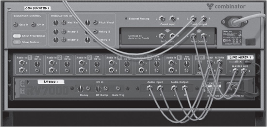
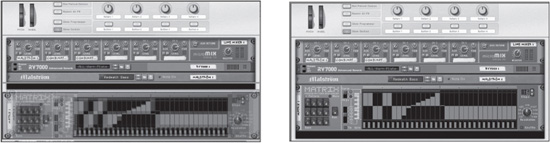
1. Click in the black space at the bottom of the Combinator, called the Holder, and notice the red insertion line (see Figure 11.7). This is where new devices will be added to the Combinator. Note that the Holder is visible only when the Show Devices button is lit on the Combinator Control Panel. Create a microMIX in the Combinator.
© Propellerhead Software AB.
2. Press Tab to flip the Rack screen around and note that the Combi Output L/R has been auto-routed to the Mix Channel inputs and that the Master Out L/R of the microMIX has been auto-routed to the Combinator’s From Devices L/R inputs. Click in the Holder space under the microMIX to show the insertion line; then create an RV7000 Advanced Reverb. Note that the Auxiliary Send of the microMIX is routed to the Audio Input L/R of the RV7000 and that the Audio Output L/R of the RV7000 is routed to the Auxiliary Return of the microMIX (see Figure 11.8).
© Propellerhead Software AB.
3. Click in the Holder under the RV7000 and create a Malström. It should auto-route to Audio In 1 of the microMIX.
4. Under the Malström, create a Matrix while holding down the Shift key on your computer keyboard. This prevents any auto-routing. Then connect the Curve CV output of the Matrix to the Wheel Modulation Input of the Malström (see Figure 11.9).
5. Under the Matrix, create a SubTractor followed by another Malström.

© Propellerhead Software AB.
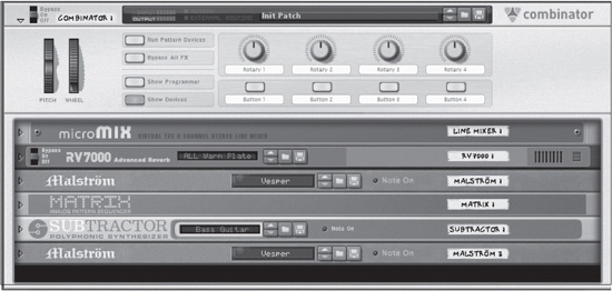
Now that your ingredients are in place, press Tab to flip the rack around so you can see the front of your devices (see Figure 11.10). Now choose some patches for your synths.
© Propellerhead Software AB.
1. Open the Patch Browser of the first Malström and choose Redeath Bass from the Bass folder in the Malström Patches folder in the Reason Factory Sound Bank.
2. Open the SubTractor’s Patch Browser and select Singing Synth from the MonoSynths folder in the SubTractor Patches folder in the Reason Factory Sound Bank.
3. Open the Patch Browser of the second Malström and choose Verbless from the PolySynths folder in the Malström Patches folder in the Reason Factory Sound Bank.
Setting the Key Ranges
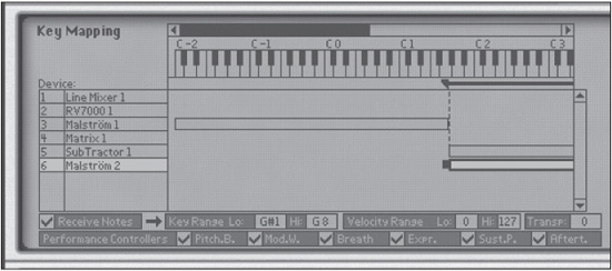
On the Combinator, click the Show Programmer button, and look at the Programmer’s Key Mapping section. On the far left, you will see a list of the devices in the Combi. As mentioned, the Key Range setting pertains mainly to instrument devices and some creative FX devices. Also, it can be adjusted only when the Receive Notes setting is active for the instrument device.
The Key Range setting can be adjusted in a few different ways. Try clicking on Malström 1 in the Combi Programmer Device List to select it. You can then click and hold on the Key Range Lo or Hi fields and move your mouse up or down to adjust the lowest and highest notes that will trigger the Malström 1. Alternatively, you can click and drag the markers at either end of the Key Range bar to the right of Malström 1. You may have to use the scroll arrows above the keyboard display to see the end markers. Finally, you can drag the entire horizontal bar to the left or right, moving the whole key zone at one time.
For this tutorial, you are going to split your keyboard so that the lowest notes trigger your Redeath Bass patch (Malström 1) and the upper keys trigger a layered lead sound. The keyboard I happen to be using is an Axiom 61, which has 61 keys, so I have plenty of room for both bass and lead sounds. If you are using a controller with fewer keys, you should adjust your split in a way that is comfortable for you. The main thing is to make sure Malström 1’s key zone covers the lowest notes on your keyboard and comes right up to, but does not overlap, the key zone of your lead sound.
1. With Malström 1 selected in the Programmer Device List, click the right scroll arrow above the keyboard display and hold it until you see the right end marker of Malström 1’s Key Range. By default, the Key Range is set to cover the entire keyboard. Click on the end marker at the far right of Malström 1’s horizontal bar and drag it to the left until it reaches G1. You have now set the Hi Key of Malström 1’s key zone to G1 (see Figure 11.11).

© Propellerhead Software AB.
2. Select SubTractor 1 in the Programmer Device List. If necessary, click the left scroll arrow above the keyboard display and hold it until you can see the left end marker of SubTractor 1’s Key Range. Click and drag SubTractor 1’s Key Range Lo marker until it reaches G#1.
3. Select Malström 2 in the Programmer Device List. Click and hold in the Key Range Lo value field and drag your mouse up until the value reads G#1. This is the same adjustment you made to SubTractor 1, done with an alternative technique. Now you have a perfectly split keyboard (see Figure 11.12).
© Propellerhead Software AB.
Before you continue with the next part of this tutorial, in which you will set the Velocity Range, some minor tweaks are in order. If you have been playing this patch at high velocities, you may have already noticed that some of your signal levels are a bit out of hand. To fix this, follow these steps:
1. On the microMIX, turn the Channel 2 SubTractor down to a value of 92 and turn the microMIX Master level down to 80. You could also rein in the SubTractor’s level by inserting a compressor, but for the sake of simplicity, just turn the channel down a bit for now.
2. Add a bit of reverb. Turn up the Channel 2 SubTractor Aux Send to a value of 48 or so.
3. Give the Malström on Channel 3 a larger dose of reverb by turning up the Channel 3 Aux Send to a value of 86.
Setting the Velocity Range
Okay, now you’re ready to set the velocity range. Follow these steps:
1. Select Malström 2 in the Programmer Device List.
2. Click in the Lo Vel field of the Velocity Range setting and drag your mouse up until you’ve set a value of 85.
Notice the diagonal stripes that have appeared on the horizontal Key Range bar of Malström 2, which will be present any time there is a velocity range of less than 127. In this case, Malström 2 will not be triggered at velocities below a value of 85. You may wish to vary this number a bit depending on the feel of your controller keyboard. You want to hear the SubTractor alone when playing soft-to-medium velocities and to hear the additional layer of Malström 2’s Verbless patch when striking the keys vigorously. This is a simple example, but I hope it will stimulate your imagination to consider the many far-out possibilities for multilayered sounds offered by the Combinator.
Run Pattern Devices
By now, you may be asking, “What did he stick that Matrix in there for, anyway?” Why, just for a little added fun! Follow these steps:
1. Set the Matrix to Curve Edit mode and draw in any old curve pattern that strikes your fancy. It’s okay to leave the Steps and Resolution controls on the Matrix at their default settings (16 and 1/16, respectively).
2. On the Combinator Control Panel, click the Run Pattern Devices button.
3. Play some low bass notes (below G#1) on your controller keyboard and check out the modulation action on your Malström Redeath Bass sound.
Once again, it’s worth noting that Run Pattern Devices is also activated automatically when you click Play on the Transport panel, and it is deactivated when you click Stop. Also, you will notice when browsing Combinator patches that Combis containing pattern devices (such as Matrix or Thor) will contain [Run] at the end of their patch name.
Modulation Routing
In the Modulation Routing section of the Programmer, you can decide what the Rotary knobs and Button controls on the Combinator Control Panel will be doing. From a performance standpoint, this is most useful when you can control those Rotary knobs and Button controls with an external MIDI controller. I discuss how to do this (Reason makes it super easy) in detail in Chapter 12, “Automation.” For now, let’s concentrate on assigning the functions of the Rotary knobs and Button controls in the Combinator Programmer.
To assign a function to a Rotary knob or Button control, first select the device in the Programmer’s Device List that contains the parameter you would like to control. Then, in the Modulation Routing section, select a parameter from the Target menu located to the right of the Rotary knob or Button control (Source) you are assigning. In this way, Rotary Knob 1, for instance, can control several different parameters for each device in the Device List simultaneously. Let’s apply some of these controls to the Combi.
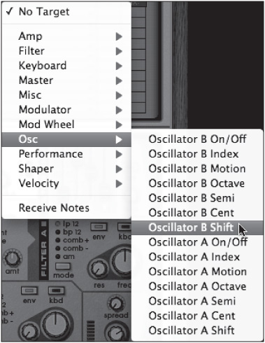
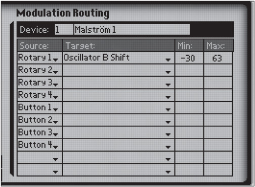
1. Select Malström 1 in the Device List. Note that it is now displayed in the Device field in the Modulation Routing section.
2. Assign Rotary Knob 1 to control the Oscillator B Shift of Malström 1 by selecting Oscillator B Shift from the Target menu to the right of Rotary 1 (see Figure 11.13).
3. Set the minimum value to −30 by clicking in the Min field and dragging your mouse down until the desired value has been selected (see Figure 11.14).
4. Find Button 1 in the Source column of the Modulation Routing section. Click in the Target field to the right of Button 1 and select Shaper Mode from the menu. The Malström has five Shaper modes, but because the Button controls can only toggle between two values, set the minimum value to 0 and the maximum value to 1. This will toggle between the Sine and Saturate Shaper modes (Saturate being the default for the Redeath Bass patch).
5. Select Line Mixer 1 in the Device List. In the Target field to the right of Rotary 2, select Channel 2 Aux Send from the menu. Set the maximum value to 99 by clicking in the Max value field and dragging the mouse down until you’ve selected the desired value. Now the amount of reverb on your SubTractor sound can be controlled with Rotary Knob 2.
© Propellerhead Software AB.
© Propellerhead Software AB.
If you’ve made it through the relatively simple Combi patch we’ve just created together, you should have a good grasp of the basic building blocks you can use to make much more complex and imaginative Combis. The sky’s the limit!
Uncombine/Combine
Before you leave your first Combi behind, if you think you might like to play with it later, be sure to save it by clicking on the Save Patch button (located to the right of Patch Browser button). Then try the following:
1. Make sure the Combinator is selected (highlighted with a light blue border) by clicking on it once. Then select Uncombine from the Edit menu. Alternatively, right-click (Windows) or Control-click (Mac) on the Combinator and select Uncombine from the pop-up menu. Now the Combinator is gone, but the devices it contained still remain and the routing is intact except that the Master outputs of microMIX are now routed to the Mix Channel, as you might expect. Of course, you no longer have any Key Range or Velocity Range information.
2. Shift-click on microMIX, RV7000, and the Malström so that all three devices are selected, highlighted with a light blue border. Then, from the Edit menu, choose Combine. Now you have a new three-device Combi.
3. Click on the right or left edge of the Matrix located just below the Combinator and drag it into the Holder until the red insertion line appears (see Figure 11.15), and drop it there. The Matrix is now part of the Combi.
© Propellerhead Software AB.
4. Shift-click on the remaining SubTractor and Malström so that they are both selected. Then select Combine from the Edit menu or right-click (Windows) or Control-click (Mac) on either of the two selected devices and select Combine from the pop-up menu. Now you’ve got a second Combinator.
5. Click on the right or left edge of the bottom Combinator and drag it into the Holder until you see the red insertion line; then let it go. The bottom Combinator has ceased to be, and its devices have been added to the first Combinator.
As you can see, the Combinator is a dynamic part of constructing your Reason songs.
Select Backdrop: More Than One Way to Skin a Combi
The last stop on our Combinator tour is not really musical, but you may find it to be a fun feature. Like Kong, the Combinator allows you to design and load your own skins. You may use any JPEG image you desire, but whatever JPEG you use should have a resolution of 754×138 pixels. In your Reason song, you can click on your Combinator and then choose Select Backdrop from the Edit menu. You are then able to select a Combi backdrop from among the JPEGs stored on your computer. In Figure 11.16, you can see what I did with Photoshop and perhaps a little too much time on my hands.
© Propellerhead Software AB.
NOTE: By the way, there used to be a Template Documents folder in the Reason program folder (or application folder) that included some Combi backdrop templates, but as of Reason version 6.0.1, that folder seems to have disappeared, even though it is mentioned in the Reason Operation Manual.
With that, we have come to the end of the introductory tour of the Combinator.
Moving On
As we end this chapter on the Combinator, I feel I should offer a few parting words. First, do not underestimate the Combinator. It is one of the most powerful devices in Reason. With it, you can mix multiple instruments to create new instruments, and create custom effects by merging other effects devices. By creating, mixing, and matching like this, you can end up really customizing you own sound and creating your own environment. Make sure and open up the Combinators that come with the factory sound bank when you run across them. In each one, you can get new ideas for your own Combinator patches!