
Chapter 17. Digital Audio Recording Basics
Once conversion from analogue signals into the digital domain has taken place, audio becomes data and a digital audio recorder is no more than a data recorder adapted to record samples from convertors. Provided that the original samples are reproduced with their numerical value unchanged and with their original time base, a digital recorder causes no loss of information at all. The only loss of information is due to the conversion processes unless there is a design fault or the equipment needs maintenance. In this chapter John Watkinson explains the various techniques needed to record audio data.
17.1. Types of Media
There is considerably more freedom of choice of digital media than was the case for analogue signals, and digital media take advantage of the research expended in computer recording.
Digital media do not need to be linear, nor do they need to be noise-free or continuous. All they need to do is allow the player to be able to distinguish some replay event, such as the generation of a pulse, from the lack of such an event with reasonable rather than perfect reliability. In a magnetic medium, the event will be a flux change from one direction of magnetization to another. In an optical medium, the event must cause the pickup to perceive a change in the intensity of the light falling on the sensor. In CD, the contrast is obtained by interference. In some discs it will be through selective absorption of light by dyes. In magneto-optical discs the recording itself is magnetic, but it is made and read using light.
17.1.1. Magnetic Recording
Magnetic recording relies on the hysteresis of certain magnetic materials. After an applied magnetic field is removed, the material remains magnetized in the same direction. By definition the process is nonlinear, and analogue magnetic recorders have to use bias to linearize it. Digital recorders are not concerned with the nonlinearity, and HF bias is unnecessary.
Figure 17.1 shows the construction of a typical digital record head, which is just like an analogue record head. A magnetic circuit carries a coil through which the record current passes and generates flux. A nonmagnetic gap forces the flux to leave the magnetic circuit of the head and penetrate the medium. The current through the head must be set to suit the coercivity of the tape and is arranged to almost saturate the track. The amplitude of the current is constant, and recording is performed by reversing the direction of the current with respect to time. As the track passes the head, this is converted to the reversal of the magnetic field left on the tape with respect to distance. The recording is actually made just after the trailing pole of the record head where the flux strength from the gap is falling. The width of the gap is generally made quite large to ensure that the full thickness of the magnetic coating is recorded, although this cannot be done if the same head is intended to replay.
Figure 17.1. Typical ferrite head windings are placed on alternate sides to save space, but parallel magnetic circuits have high cross talk.
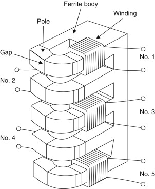
Figure 17.2 shows what happens when a conventional inductive head, that is, one having a normal winding, is used to replay the track made by reversing the record current. The head output is proportional to the rate of change of flux and so only occurs at flux reversals. The polarity of the resultant pulses alternates as the flux changes and changes back. A circuit is necessary which locates the peaks of the pulses and outputs a signal corresponding to the original record current waveform.
Figure 17.2. Basic digital recording. At (a) the write current in the head is reversed from time to time, leaving a binary magnetization pattern shown at (b). When replayed, the waveform at (c) results because an output is only produced when flux in the head changes. Changes are referred to as transitions.

The head shown in Figure 17.2 has the frequency response shown in Figure 17.3. At DC there is no change of flux and no output. As a result, inductive heads are at a disadvantage at very low speeds. The output rises with frequency until the rise is halted by the onset of thickness loss. As the frequency rises, the recorded wavelength falls and flux from the shorter magnetic patterns cannot be picked up so far away. At some point, the wavelength becomes so short that flux from the back of the tape coating cannot reach the head and a decreasing thickness of tape contributes to the replay signal. In digital recorders using short wavelengths to obtain high density, there is no point in using thick coatings. As wavelength further reduces, the familiar gap loss occurs, where the head gap is too big to resolve detail on the track.
Figure 17.3. The major mechanisms defining magnetic channel bandwidth.

As can be seen, the frequency response is far from ideal, and steps must be taken to ensure that recorded data waveforms do not contain frequencies which suffer excessive losses.
A more recent development is the magneto-resistive (MR) head. This is a head that measures the flux on the tape rather than using it to generate a signal directly. Flux measurement works down to DC and so offers advantages at low tape speeds. Unfortunately, flux measuring heads are not polarity conscious and if used directly they sense positive and negative flux equally, as shown in Figure 17.4. This is overcome by using a small extra winding carrying a constant current. This creates a steady bias field, which adds to the flux from the tape. The flux seen by the head now changes between two levels and a better output waveform results.
Figure 17.4. The sensing element in a magneto-resistive head. Transitions are not sensitive to the polarity of the flux, only the magnitude. At (a) the track magnetization is shown, which causes a bidirectional flux variation in the head as at (b) resulting in the magnitude output at (c). However, if the flux in the head due to the track is biased by an additional field, it can be made unipolar as at (d) and the correct output waveform is obtained.

Recorders that have low head-to-medium speed, such as digital compact cassette (DCC) use MR heads, whereas recorders with high speeds, such as digital audio stationary head (DASH), rotary head digital audio tape (RDAT), and magnetic disc drives, use inductive heads.
Heads designed for use with tape work in actual contact with the magnetic coating. The tape is tensioned to pull it against the head. There will be a wear mechanism and need for periodic cleaning.
In the hard disc, the rotational speed is high in order to reduce access time, and the drive must be capable of staying on line for extended periods. In this case the heads do not contact the disc surface, but are supported on a boundary layer of air. The presence of the air film causes spacing loss, which restricts the wavelengths at which the head can replay. This is the penalty of rapid access.
Digital audio recorders must operate at high density in order to offer a reasonable playing time. This implies that the shortest possible wavelengths will be used. Figure 17.5 shows that when two flux changes, or transitions, are recorded close together, they affect each other on replay. The amplitude of the composite signal is reduced, and the position of the peaks is pushed outward. This is known as intersymbol interference, or peak-shift distortion, and occurs in all magnetic media.
Figure 17.5. (a) Peak shift distortion can be reduced by (b) equalization in replay or (c) precompensation.


The effect is primarily due to high frequency loss and it can be reduced by equalization on replay, as is done in most tapes, or by precompensation on record, as is done in hard discs.
17.1.2. Optical Discs
Optical recorders have the advantage that light can be focused at a distance whereas magnetism cannot. This means that there need be no physical contact between the pickup and the medium and no wear mechanism.
In the same way that the recorded wavelength of a magnetic recording is limited by the gap in the replay head, the density of optical recording is limited by the size of light spot which can be focused on the medium. This is controlled by the wavelength of the light used and by the aperture of the lens. When the light spot is as small as these limits allow, it is said to be diffraction limited. The recorded details on the disc are minute, and could easily be obscured by dust particles. In practice the information layer needs to be protected by a thick transparent coating. Light enters the coating well out of focus over a large area so that it can pass around dust particles, and comes to a focus within the thickness of the coating. Although the number of bits per unit area is high in optical recorders, the number of bits per unit volume is not as high as that of tape because of the thickness of the coating.
Figure 17.6 shows the principle of readout of the compact disc which is a read-only disc manufactured by pressing. The track consists of raised bumps separated by flat areas. The entire surface of the disc is metalized, and the bumps are one quarter of a wavelength in height. The player spot is arranged so that half of its light falls on top of a bump, and half on the surrounding surface. Light returning from the flat surface has traveled half a wavelength further than light returning from the top of the bump, and so there is a phase reversal between the two components of the reflection. This causes destructive interference, and light cannot return to the pickup. It must reflect at angles which are outside the aperture of the lens and be lost. Conversely, when light falls on the flat surface between bumps, the majority of it is reflected back to the pickup. The pickup thus sees a disc apparently having alternately good or poor reflectivity.
Figure 17.6. CD readout principle and dimensions. The presence of a bump causes destructive interference in the reflected light.

Some discs can be recorded once, but not subsequently erased or rerecorded. These are known as WORM (write once read mostly) discs. One type of WORM disc uses a thin metal layer that has holes punched in it on recording by heat from a laser. Others rely on the heat raising blisters in a thin metallic layer by decomposing the plastic material beneath. Yet another alternative is a layer of photo-chemical dye that darkens when struck by the high powered recording beam. Whatever the recording principle, light from the pickup is reflected more or less, or absorbed more or less, so that the pickup once more senses a change in reflectivity. Certain WORM discs can be read by conventional CD players and are thus called recordable CDs, whereas others will only work in a particular type of drive.
17.1.3. Magneto-Optical Discs
When a magnetic material is heated above its Curie temperature, it becomes demagnetized, and on cooling will assume the magnetization of an applied field which would be too weak to influence it normally. This is the principle of magneto-optical recording used in the Sony MiniDisc. The heat is supplied by a finely focused laser; the field is supplied by a coil that is much larger.
Figure 17.7 assumes that the medium is initially magnetized in one direction only. In order to record, the coil is energized with the waveform to be recorded. This is too weak to influence the medium in its normal state, but when it is heated by the recording laser beam the heated area will take on the magnetism from the coil when it cools. Thus a magnetic recording with very small dimensions can be made.
Figure 17.7. The thermomagneto-optical disk uses the heat from a laser to allow a magnetic field to record on the disk.

Readout is obtained using the Kerr effect, which is the rotation of the plane of polarization of light by a magnetic field. The angle of rotation is very small and needs a sensitive pickup. The recording can be overwritten by reversing the current in the coil and running the laser continuously as it passes along the track.
A disadvantage of magneto-optical recording is that all materials having a Curie point low enough to be useful are highly corrodible by air and need to be kept under an effectively sealed protective layer.
All optical discs need mechanisms to keep the pickup following the track and sharply focused on it.
The frequency response of an optical disc is shown in Figure 17.8. The response is best at DC and falls steadily to the optical cut-off frequency. Although the optics work down to DC, this cannot be used for the data recording. DC and low frequencies in data would interfere with the focus and tracking servos. In practice the signal from the pickup is split by a filter. Low frequencies go to the servos, and higher frequencies go to the data circuitry. As a result, the data channel has the same inability to handle DC as does a magnetic recorder, and the same techniques are needed to overcome it.
Figure 17.8. Frequency response of laser pickup. Maximum operating frequency is about half of cutoff frequency Fc.

17.2. Recording Media Compared
Of the various media discussed so far, it might be thought that one would be the best and would displace all the others. This has not happened because there is no one best medium; it depends on the application.
Random access memory (RAM) offers extremely short access time, but the volume of data generated by digital audio precludes the use of RAM for anything more than a few seconds because it would be too expensive. In addition loss of power causes the recording to be lost.
Tape has the advantage that it is thin and can be held compactly on reels. However, this slows down the access time because the tape has to be wound, or shuttled, to the appropriate place. Tape is, however, inexpensive, long lasting, and is appropriate for archiving large quantities of data.
However, discs allow rapid access because their entire surface is permanently exposed and the positioner can move the heads to any location in a matter of milliseconds. The capacity is limited compared to tape because in the case of magnetic discs there is an air gap between the medium and the head. Exchangeable discs have to have a certain minimum head flying height below which the risk of contamination and a consequent head crash is too great. In Winchester technology the heads and disc are sealed inside a single assembly and contaminants can be excluded. In this case the flying height can be reduced and the packing density increased as a consequence. However, the disc is no longer exchangeable. In the case of optical discs the medium itself is extremely thick and multiple platter drives are impracticable because of the size of the optical pickup.
If the criterion is access time, discs are to be preferred. If the criterion is compact storage, tape is to be preferred. In computers, both technologies have been used in a complementary fashion for many years. In digital audio the same approach could be used, but to date the steps appear faltering.
In tape recording, the choice is between rotary and stationary heads. In a stationary head machine, the narrow tracks required by digital recordings result in heads with many parallel magnetic circuits, each of which requires its own read and write circuitry. Gaps known as guard bands must be placed between the tracks to reduce cross talk. Guard bands represent wasted tape.
In rotary head machines, the tracks are laid down by a small number of rapidly rotating heads and less read/write circuitry is required. The space between the tracks is controlled by the linear tape speed and not by head geometry and so any spacing can be used. If azimuth recording is used, no guard bands are necessary. A further advantage of rotary head recorders is that the high head to tape speed raises the frequency of the off-tape signals, and with a conventional inductive head, this results in a larger playback signal compared to the thermal noise from the head and the preamplifiers.
As a result the rotary head tape recorder offers the highest storage density yet achieved, despite the fact that available formats are not yet in sight of any fundamental performance limits.
17.3. Some Digital Audio Processes Outlined
While digital audio is a large subject, it is not necessarily a difficult one. Every process can be broken down into smaller steps, each of which is relatively easy to assimilate. The main difficulty with study is not following the simple step, but to appreciate where it fits in the overall picture. The next few sections illustrate various important processes in digital audio and show why they are necessary. Such processes are combined in various ways in real equipment.
17.3.1. The Sampler
Figure 17.9 consists of an ADC, which is joined to a DAC by way of a quantity of RAM. What the device does is determined by the way in which the RAM address is controlled. If the RAM address increases by one every time a sample from the ADC is stored in the RAM, a recording can be made for a short period until the RAM is full. The recording can be played back by repeating the address sequence at the same clock rate but reading data from the memory into the DAC. The result is generally called a sampler. By running the replay clock at various rates, the pitch and duration of the reproduced sound can be altered. At a rate of one million bits per second, a megabyte of memory gives only 8 s worth of recording, so clearly samplers will be restricted to a fairly short playing time.
Figure 17.9. In the digital sampler, the recording medium is a RAM. Recording time available is short compared to other media, but access to the recording is immediate and flexible as it is controlled by addressing the RAM.

Using data reduction, the playing time of a RAM based recorder can be extended. Some telephone answering machines take messages in RAM and eliminate the cassette tape. For predetermined messages, read only memory can be used instead as it is nonvolatile. Announcements in aircraft, trains, and elevators are one application of such devices.
17.3.2. The Programmable Delay
If the RAM of Figure 17.9 is used in a different way, it can be written and read at the same time. The device then becomes an audio delay. Controlling the relationship between the addresses then changes the delay. The addresses are generated by counters that overflow to zero after they have reached a maximum count. As a result the memory space appears to be circular as shown in Figure 17.10. The read and write addresses are driven by a common clock and chase one another around the circle. If the read address follows close behind the write address, the delay is short. If it just stays ahead of the write address, the maximum delay is reached. Programmable delays are useful in TV studios where they allow audio to be aligned with video which has been delayed in various processes. They can also be used in auditoria to align the sound from various loudspeakers.
Figure 17.10. Time base corrector (TBC) memory is addressed by a counter that overflows periodically to give a ring structure. Memory allows read side to be nonsynchronous with write side.

In digital audio recorders, a device with a circular memory can be used to remove irregularities from the replay data rate. The off-tape data rate can fluctuate within limits but the output data rate can be held constant. A memory used in this way is called a time base corrector (TBC). All digital recorders have TBCs to eliminate wow and flutter.
17.3.3. Time Compression
When samples are converted, the ADC must run at a constant clock rate and it outputs an unbroken stream of samples. Time compression allows the sample stream to be broken into blocks for convenient handling.
Figure 17.11 shows an ADC feeding a pair of RAMS. When one is being written by the ADC, the other can be read, and vice versa. As soon as the first RAM is full, the ADC output switched to the input of the other RAM so that there is no loss of samples. The first RAM can then be read at a higher clock rate than the sampling rate. As a result the RAM is read in less time than it took to write it, and the output from the system then pauses until the second RAM is full. The samples are now time compressed. Instead of being an unbroken stream, which is difficult to handle, the samples are now arranged in blocks with convenient pauses in between them. 1n these pauses numerous processes can take place. A rotary head recorder might switch heads; a hard disc might move to another track. On a tape recording, the time compression of the audio samples allows time for synchronizing patterns, subcode, and error-correction words to be recorded.
Figure 17.11. In time compression, the unbroken real-time stream of samples from an ADC is broken up into discrete blocks. This is accomplished by the configuration shown here. Samples are written into one RAM at the sampling rate by the write clock. When the first RAM is full, the switches change over, and writing continues into the second RAM while the first is read using a higher frequency clock. The RAM is read faster than it was written and so all data will be output before the other RAM is full. This opens spaces in the data flow, which are used as described in the text.

In digital audio recorders that use video cassette recorders (VCRs), time compression allows the continuous audio samples to be placed in blocks in the unblanked parts of the video waveform, separated by synchronizing pulses.
Subsequently, any time compression can be reversed by time expansion. Samples are written into a RAM at the incoming clock rate, but read out at the standard sampling rate. Unless there is a design fault, time compression is totally inaudible. In a recorder, the time-expansion stage can be combined with the time base-correction stage so that speed variations in the medium can be eliminated at the same time. The use of time compression is universal in digital audio recording. In general the instantaneous data rate at the medium is not the same as the rate at the convertors, although clearly the average rate must be the same.
Another application of time compression is to allow more than one channel of audio to be carried on a single cable. If, for example, audio samples are time compressed by a factor of two, it is possible to carry samples from a stereo source in one cable.
In digital video recorders, both audio and video data are time compressed so that they can share the same heads and tape tracks.
17.3.4. Synchronization
In addition to the analogue inputs and outputs, connected to convertors, many digital recorders have digital inputs that allow the convertors to be bypassed. This mode of connection is desirable because there is no loss of quality in a digital transfer. Transfer of samples between digital audio devices is only possible if both use a common sampling rate and they are synchronized. A digital audio recorder must be able to synchronize to the sampling rate of a digital input in order to record the samples. It is frequently necessary for such a recorder to be able to play back locked to an external sampling rate reference so that it can be connected to, for example, a digital mixer. The process is already common in video systems but now extends to digital audio.
Figure 17.12 shows how the external reference locking process works. The time base expansion is controlled by the external reference, which becomes the read clock for the RAM and so determines the rate at which the RAM address changes. In the case of a digital tape deck, the write clock for the RAM would be proportional to the tape speed. If the tape is going too fast, the write address will catch up with the read address in the memory, whereas if the tape is going too slow the read address will catch up with the write address. The tape speed is controlled by subtracting the read address from the write address. The address difference is used to control the tape speed. Thus if the tape speed is too high, the memory will fill faster than it is being emptied, and the address difference will grow larger than normal. This slows down the tape.
Figure 17.12. In a recorder using time compression, the samples can be returned to a continuous stream using RAM as a TBC. The long-term data rate has to be the same on the input and output of the TBC or it will lose data. This is accomplished by comparing the read and write addresses and using the difference to control the tape speed. In this way the tape speed will automatically adjust to provide data as fast as the reference clock takes it from the TBC.

Thus in a digital recorder the speed of the medium is constantly changing to keep the data rate correct. Clearly this is inaudible as properly engineered time base correction totally isolates any instabilities on the medium from data fed to the convertor.
In multitrack recorders, the various tracks can be synchronized to sample accuracy so that no timing errors can exist between the tracks. In stereo recorders image shift due to phase errors is eliminated.
In order to replay without a reference, perhaps to provide an analogue output, a digital recorder generates a sampling clock locally by means of a crystal oscillator. Provision will be made on professional machines to switch between internal and external references.
17.3.5. Error Correction and Concealment
As anyone familiar with analogue recording will know, magnetic tape is an imperfect medium. It suffers from noise and dropouts, which in analogue recording are audible. In a digital recording of binary data, a bit is either correct or wrong, with no intermediate stage. Small amounts of noise are rejected, but inevitably, infrequent noise impulses cause some individual bits to be in error. Dropouts cause a larger number of bits in one place to be in error. An error of this kind is called a burst error. Whatever the medium and whatever the nature of the mechanism responsible, data are either recovered correctly, or suffer some combination of bit errors and burst errors. In compact disc, random errors can be caused by imperfections in the moulding process, whereas burst errors are due to contamination or scratching of the disc surface.
The audibility of a bit error depends on which bit of the sample is involved. If the LSB of one sample was in error in a loud passage of music, the effect would be totally masked and no one could detect it. Conversely, if the MSB of one sample was in error in a quiet passage, no one could fail to notice the resulting loud transient. Clearly a means is needed to render errors from the medium inaudible. This is the purpose of error correction.
In binary, a bit has only two states. If it is wrong, it is only necessary to reverse the state and it must be right. Thus the correction process is trivial and perfect. The main difficulty is in identifying the bits that are in error. This is done by coding the data by adding redundant bits. Adding redundancy is not confined to digital technology, airliners have several engines and cars have twin braking systems. Clearly the more failures that have to be handled, the more redundancy is needed. If a four-engined airliner is designed to fly normally with one engine failed, three of the engines have enough power to reach cruise speed, and the fourth one is redundant. The amount of redundancy is equal to the amount of failure that can be handled. In the case of the failure of two engines, the plane can still fly, but it must slow down; this is graceful degradation. Clearly the chances of a two-engine failure on the same flight are remote.
In digital audio, the amount of error that can be corrected is proportional to the amount of redundancy and within this limit the samples are returned to exactly their original value. Consequently corrected samples are inaudible. If the amount of error exceeds the amount of redundancy, correction is not possible, and, in order to allow graceful degradation, concealment will be used. Concealment is a process where the value of a missing sample is estimated from those nearby. The estimated sample value is not necessarily exactly the same as the original, and so under some circumstances concealment can be audible, especially if it is frequent. However, in a well-designed system, concealments occur with negligible frequency unless there is an actual fault or problem.
Concealment is made possible by rearranging or shuffling the sample sequence prior to recording. This is shown in Figure 17.13 where odd-numbered samples are separated from even-numbered samples prior to recording. The odd and even sets of samples may be recorded in different places, so that an uncorrectable burst error only affects one set. On replay, the samples are recombined into their natural sequence, and the error is now split up so that it results in every other sample being lost. The waveform is now described half as often, but can still be reproduced with some loss of accuracy. This is better than not being reproduced at all even if it is not perfect. Almost all digital recorders use such an odd-even shuffle for concealment. Clearly if any errors are fully correctable, the shuffle is a waste of time; it is only needed if correction is not possible.
Figure 17.13. In cases where the error correction is inadequate, concealment can be used provided that the samples have been ordered appropriately in the recording. Odd and even samples are recorded in different places as shown here. As a result an uncorrectable error causes incorrect samples to occur singly, between correct samples. In the example shown, sample 8 is incorrect, but samples 7 and 9 are unaffected and an approximation to the value of sample 8 can be had by taking the average value of the two. This interpolated value is substituted for the incorrect value.

In high-density recorders, more data are lost in a given sized dropout. Adding redundancy equal to the size of a dropout to every code is inefficient. Figure 17.14(a) shows that the efficiency of the system can be raised using interleaving. Sequential samples from the ADC are assembled into codes, but these are not recorded in their natural sequence. A number of sequential codes are assembled along rows in a memory. When the memory is full, it is copied to the medium by reading down columns. On replay, the samples need to be deinterleaved to return them to their natural sequence. This is done by writing samples from tape into a memory in columns, and when it is full, the memory is read in rows. Samples read from the memory are now in their original sequence so there is no effect on the recording. However, if a burst error occurs on the medium, it will damage sequential samples in a vertical direction in the deinterleave memory. When the memory is read, a single large error is broken down into a number of small errors whose size is exactly equal to the correcting power of the codes and the correction is performed with maximum efficiency.
Figure 17.14(a). Interleaving is essential to make error correction schemes more efficient. Samples written sequentially in rows into a memory have redundancy P added to each row. The memory is then read in columns and data are sent to the recording medium. On replay, the nonsequential samples from the medium are deinterleaved to return them to their normal sequence. This breaks up the burst error (shaded) into one error symbol per row in the memory, which can be corrected by the redundancy P.

An extension of the process of interleave is where the memory array has not only rows made into code words, but also columns made into code words by the addition of vertical redundancy. This is known as a product code. Figure 17.14(b) shows that in a product code the redundancy calculated first and checked last is called the outer code, and the redundancy calculated second and checked first is called the inner code. The inner code is formed along tracks on the medium. Random errors due to noise are corrected by the inner code and do not impair the burst correcting power of the outer code. Burst errors are declared uncorrectable by the inner code, which flags the bad samples on the way into the deinterleave memory. The outer code reads the error flags in order to locate erroneous data. As it does not have to compute the error locations, the outer code can correct more errors.
Figure 17.14(b). In addition to the redundancy P on rows, inner redundancy Q is also generated on columns. On replay, the Q code checker will pass on flags F if it finds an error too large to handle itself. The flags pass through the deinterleave process and are used by the outer error correction to identify which symbol in the row needs correcting with P redundancy. The concept of crossing two codes in this way is called a product code.

An alternative to the product block code is the convolutional cross interleave, shown in Figure 17.14(c). In this system, data are formed into an endless array and the code words are produced on columns and diagonals. The compact disc and DASH formats use such a system because it needs less memory than a product code.
Figure 17.14(c). Convolutional interleave is shown. Instead of assembling samples in blocks, the process is continuous and uses RAM delays. Samples are formed into columns in an endless array. Each row of the array is subject to a different delay so that after the delays, samples in a column are available simultaneously which were previously on a diagonal. Code words which cross one another at an angle can be obtained by generating redundancy before and after the delays.

The interleave, deinterleave, time-compression, and time base-correction processes cause delay and this is evident in the time taken before audio emerges after starting a digital machine. Confidence replay takes place later than the distance between record and replay heads would indicate. In DASH format recorders, confidence replay is about one-tenth of a second behind the input. Synchronous recording requires new techniques to overcome the effect of the delays.
The presence of an error-correction system means that the audio quality is independent of the tape/head quality within limits. There is no point in trying to assess the health of a machine by listening to it, as this will not reveal whether the error rate is normal or within a whisker of failure. The only useful procedure is to monitor the frequency with which errors are being corrected and to compare it with normal figures. Professional digital audio equipment should have an error rate display.
Some people claim to be able to hear error correction and misguidedly conclude that the aforementioned theory is flawed. Not all digital audio machines are properly engineered, however, and if the DAC shares a common power supply with the error correction logic, a burst of errors will raise the current taken by the logic, which loads the power supply and can interfere with the operation of the DAC. The effect is harder to eliminate in small battery-powered machines where space for screening and decoupling components is hard to find, but it is only a matter of design: there is no flaw in the theory.
17.3.6. Channel Coding
In most recorders used for storing digital information, the medium carries a track that reproduces a single waveform. Clearly data words representing audio samples contain many bits and so they have to be recorded serially, a bit at a time. Some media, such as CD, only have one track, so it must be totally self-contained. Other media, such as DCC, have many parallel tracks. At high recording densities, physical tolerances cause phase shifts, or timing errors, between parallel tracks and so it is not possible to read them in parallel. Each track must still be self-contained until the replayed signal has been time base corrected.
Recording data serially is not as simple as connecting the serial output of a shift register to the head. In digital audio, a common sample value is all zeros, as this corresponds to silence. If a shift register is loaded with all zeros and shifted out serially, the output stays at a constant low level, and nothing is recorded on the track. On replay there is nothing to indicate how many zeros were present or even how fast to move the medium. Clearly serialized raw data cannot be recorded directly, it has to be modulated into a waveform that contains an embedded clock irrespective of the values of the bits in the samples. On replay a circuit called a data separator can lock to the embedded clock and use it to separate strings of identical bits.
The process of modulating serial data to make it self-clocking is called channel coding. Channel coding also shapes the spectrum of the serialized waveform to make it more efficient. With a good channel code, more data can be stored on a given medium. Spectrum shaping is used in CD to prevent data from interfering with the focus and tracking servos and in RDAT to allow rerecording without erase heads.
A self-clocking code contains a guaranteed minimum number of transitions per unit time, and these transitions must occur at multiples of some basic time period so that they can be used to synchronize a phase locked loop. Figure 17.15 shows a phase-locked loop that contains an oscillator whose frequency is controlled by the phase error between input transitions and the output of a divider. If transitions on the medium are constrained to occur at multiples of a basic time period, they will have a constant phase relationship with the oscillator, which can stay in lock with them even if they are intermittent. As the damping of the loop is a low-pass filter, jitter in the incoming transitions, caused by peak-shift distortion or by speed variations in the medium, will be rejected and the oscillator will run at the average frequency of the off-tape signal. The phase-locked loop must be locked before data can be recovered, and to enable this, every data block is preceded by a constant frequency recording known as a preamble. The beginning of data is identified by a unique pattern known as a sync pattern.
Figure 17.15. A typical phase-locked loop where the VCO is forced to run at a multiple of the input frequency. If the input ceases, the output will continue at the same frequency until it drifts.

Irrespective of the channel code used, transitions always occur separated by a range of time periods which are all multiples of the basic clock period. If such a replay signal is viewed on an oscilloscope, a characteristic display called an eye pattern is obtained. Figure 17.16 shows an eye pattern, and in particular the regular openings in the trace. A decision point is in the center of each opening, and the phase-locked loop acts to keep it centered laterally, in order to reject the maximum amount of jitter. At each decision point along the time axis, the waveform is above or below the point, and can be returned to a binary signal.
Figure 17.16. At the decision points, the receiver must make binary decisions about the voltage of the signal, whether it is above or below the slicing level. If the eyes remain open, this will be possible in the presence of noise and jitter.

Occasionally, noise or jitter will cause the waveform to pass the wrong side of a decision point, and this will result in an error that will require correction.
Figure 17.17 shows an extremely simple channel code known as frequency modulation (FM), which is used for the AES/EBU digital interface and for recording time code on tape.
Figure 17.17. FM channel code, also known as Manchester code or biphase mark, is used in AESEBU interface and for time code recording. The waveform is encoded as shown here. See text for details.

Every bit period begins with a transition, irrespective of the value of the bit. If the bit is a one, an additional transition is placed in the center of the bit period. If the bit is a zero, this transition is absent. As a result, the waveform is always self-clocking irrespective of the values of the data bits. Additionally, the waveform spends as much time in the low state as it does in the high state. This means that the signal has no DC component and will pass through capacitors, magnetic heads, and transformers equally well. However simple FM may be, it is not very efficient because it requires two transitions for every bit and jitter of more than half a bit cannot be rejected.
More recent products use a family of channel codes known as group codes. In group codes, groups of bits, commonly eight, are associated together into a symbol for recording purposes. Eight-bit symbols are common in digital audio because two of them can represent a 16-bit sample. Eight-bit data have 256 possible combinations, but if the waveforms obtained by serializing them are examined, it will be seen that many combinations are unrecordable. For example, all ones or all zeros cannot be recorded because they contain no transitions to lock the clock and they have excessive DC content. If a larger number of bits is considered, a greater number of combinations is available. After the unrecordable combinations have been rejected, there will still be 256 left which can each represent a different combination of eight bits. The larger number of bits are channel bits; they are not data because all combinations are not recordable. Channel bits are simply a convenient way of generating recordable waveforms. Combinations of channel bits are selected or rejected according to limits on the maximum and minimum periods between transitions. These periods are called run-length limits and as a result group codes are often called run-length-limited codes.
In RDAT, an 8/10 code is used where 8 data bits are represented by 10 channel bits. Figure 17.18 shows that this results in jitter rejection of 80% of a data bit period: rather better than FM. Jitter rejection is important in RDAT because short wavelengths are used and peak shift will occur. The maximum wavelength is also restricted in RDAT so that low frequencies do not occur.
Figure 17.18. In RDAT an 8/10 code is used for recording. Each 8 data bits are represented by a unique waveform generated by 10 channel bits. A channel bit one causes a transition to be recorded. The transitions cannot be closer than 0.8 of a data bit, and this is the jitter resistance. This is rather better than FM, which has a jitter window of only 0.5 bits.

In CD, an 8/14 code is used where 8 data bits are represented by 14 channel bits. This only has a jitter rejection of 8/14 of a data bit, but this is not an issue because the rigid CD has low jitter. However, in 14 bits there are 16K combinations, and this is enough to impose a minimum run length limit of 3 channel bits. In other words, transitions on the disc cannot occur closer than 3 channel bits apart. This corresponds to 24/14 data bits. Thus the frequency generated is less than the bit rate and a result is that more data can be recorded on the disc than would be possible with a simple code.
17.4. Hard Disc Recorders
The hard disc recorder stores data on concentric tracks, which it accesses by moving the head radially. Rapid access drives move the heads with a moving coil actuator, whereas lower cost units will use stepping motors, which work more slowly. The radial position of the head is called the cylinder address, and as the disc rotates, data blocks, often called sectors, pass under the head. To increase storage capacity, many discs can be mounted on a common spindle, each with its own head. All the heads move on a common positioner. The operating surface can be selected by switching on only one of the heads. When one track is full, the drive must select another head. When every track at that cylinder is full, the drive must move to another cylinder. The drive is not forced to operate in this way; it is equally capable of obtaining data blocks in any physical sequence from the disc.
Clearly while the head is moving it cannot transfer data. Using time compression to smooth out the irregular data transfer, a hard disc drive can be made into an audio recorder with the addition of a certain amount of memory.
Figure 17.19 shows the principle. The instantaneous data rate of the disc drive is far in excess of the sampling rate at the convertor, and so a large time-compression factor can be used. The disc drive can read a block of data from disc and place it in the TBC in a fraction of the real time it represents in the audio waveform. As the TBC steadily advances through the memory, the disc drive has time to move the heads to another track before the memory runs out of data. When there is sufficient space in the memory for another block, the drive is commanded to read and fills up the space. Although the data transfer at the medium is highly discontinuous, the buffer memory provides an unbroken stream of samples to the DAC and so continuous audio is obtained.
Figure 17.19. During an audio replay sequence, the silo is constantly emptied to provide samples and is refilled in blocks by the drive.

Recording is performed using the memory to assemble samples until the contents of one disc block are available. These are then transferred to disc at high data rate. The drive can then reposition the head before the next block is available in memory.
An advantage of hard discs is that access to the audio is much quicker than with tape, as all of the data are available within the time taken to move the head. This speeds up editing considerably.
After a disc has been in use for some time, the free blocks will be scattered all over the disc surface. The random access ability of the disc drive means that a continuous audio recording can be made on physically discontinuous blocks. Each block has a physical address, known as the block address, which the drive controller can convert into cylinder and head selection codes to locate a given physical place on the medium. The size of each block on the disc is arranged to hold the number of samples that arrive during a whole number of time code frames. It is then possible to link each disc block address used during a recording with the time code at which it occurred. The time codes and the corresponding blocks are stored in a table. The table is also recorded on the disc when the recording is completed.
In order to replay the recording, the table is retrieved from the disc, and a time code generator is started at the first code. As the generator runs, each code is generated in sequence, and the appropriate data block is read from the disc and placed in memory, where it can be fed to the convertor.
If it is desired to replay the recording from elsewhere than the beginning, the time code generator can be forced to any appropriate setting, and the recording will play from there. If an external device, such as a video recorder, provides a time code signal, this can be used instead of the internal time code generator, and the machine will automatically synchronize to it.
The transfer rate and access time of the disc drive are such that if sufficient memory and another convertor are available, two completely independent playback processes can be supplied with data by the same drive. For the purpose of editing, two playback processes can be controlled by one time code generator. The time code generator output can be offset differently for each process, so that they can play back with any time relationship. If it is required to join the beginning of one recording to the end of another, the operator specifies the in point on the second recording and the out point on the second recording. By changing the time code offsets, the machine can cause both points to occur simultaneously in data accessed from the disc and played from memory. In the vicinity of the edit points, both processes are providing samples simultaneously and a cross fade of any desired length can be made between them.
The arrangement of data on the disc surface has a bearing on the edit process. In the worst case, if all the blocks of the first recording were located at the outside of the disc and all of the blocks of the second recording were located at the inside, the positioner would spend a lot of time moving. If the blocks for all recordings are scattered over the entire disc surface, the average distance the positioner needs to move is reduced.
The edit can be repeated with different settings as often as necessary without changing the original recordings. Once an edit is found to be correct, it is only necessary to store the handful of instructions which caused it to happen, and it can be executed at any time in the future in the same way. The operator has the choice of archiving the whole disc contents on tape, so different edits can be made in the future, or simply recording the output of the current edit so that the disc can be freed for another job.
The rapid access and editing accuracy of hard disc systems make them ideal for assembling sound effects to make the sound tracks of motion pictures.
The use of data reduction allows the recording time of a disc to be extended considerably. This technique is often used in plug-in circuit boards, which are used to convert a personal computer into a digital audio recorder.
17.5. The PCM Adaptor
The PCM adaptor was an early solution to recording the wide bandwidth of PCM audio before high-density digital recording developed. The video recorder offered sufficient bandwidth at moderate tape consumption. While they were a breakthrough at the time of their introduction, by modern standards PCM adaptors are crude and obsolescent, offering limited editing ability and slow operation.
Figure 17.20 shows the essential components of a digital audio recorder using this technique. Input analogue audio is converted to digital and time compressed to fit into the parts of the video waveform which are not blanked. Time-compressed samples are then odd-even shuffled to allow concealment. Next, redundancy is added and data are interleaved for recording. Data are serialized and set on the active line of the video signal as black and white levels shown in Figure 17.21. The video is sent to the recorder, where the analogue FM modulator switches between two frequencies representing the black and white levels, a system called frequency shift keying (FSK). This takes the place of the channel coder in a conventional digital recorder.
Figure 17.20. Block diagram of PCM adaptor. Note the dub connection needed for producing a digital copy between two VCRs.

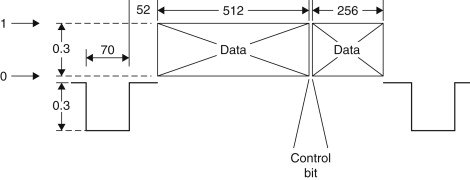
Figure 17.21. Typical line of video from PCM-1610. The control bit conveys the setting of the preemphasis switch or the sampling rate, depending on the frame. The bits are separated using only the timing information in the sync pulses.
On replay, the FM demodulator of the video recorder acts to return the FSK recording to the black/white video waveform, which is sent to the PCM adaptor. The PCM adaptor extracts a clock from the video sync pulses and uses it to separate the serially recorded bits. Error correction is performed after deinterleaving, unless the errors are too great, in which case concealment is used after the deshuffle. The samples are then returned to the standard sampling rate by the time base expansion process, which also eliminates any speed variations from the recorder. They can then be converted back to the analogue domain.
In order to synchronize playback to a reference and to simplify the circuitry, a whole number of samples is recorded on each unblanked line. The common sampling rate of 44.1 kHz is obtained by recording three samples per line on 245 active lines at 60 Hz. The sampling rate is thus locked to the video sync frequencies and the tape is made to move at the correct speed by sending the video recorder syncs which are generated in the PCM adaptor.
17.6. An Open Reel Digital Recorder
Figure 17.22 shows the block diagram of a machine of this type. Analogue inputs are converted to the digital domain by converters. Clearly there will be one convertor for every audio channel to be recorded. Unlike an analogue machine, there is not necessarily one tape track per audio channel. In stereo machines the two channels of audio samples may be distributed over a number of tracks each in order to reduce the tape speed and extend the playing time.
Figure 17.22. Block diagram of one channel of a stationary head digital audio recorder. See text for details of the function of each block. Note the connection from the TBC to the capstan motor so that the tape is played at such a speed that the TBC memory neither underflows nor overflows.

The samples from the convertor will be separated into odd and even for concealment purposes, and usually one set of samples will be delayed with respect to the other before recording. The continuous stream of samples from the convertor will be broken into blocks by time compression prior to recording. Time compression allows the insertion of edit gaps, addresses, and redundancy into the data stream. An interleaving process is also necessary to reorder the samples prior to recording. As explained earlier, the subsequent deinterleaving breaks up the effects of burst errors on replay.
The result of the processes so far is still raw data, which will need to be channel coded before they can be recorded on the medium. On replay a data separator reverses the channel coding to give the original raw data with the addition of some errors. Following deinterleave, the errors are reduced in size and are more readily correctable. The memory required for deinterleave may double as the TBC memory, so that variations in the speed of the tape are rendered undetectable. Any errors that are beyond the power of the correction system will be concealed after the odd-even shift is reversed. Following conversion in the DAC an analogue output emerges.
On replay a digital recorder works rather differently to an analogue recorder, which simply drives the tape at constant speed. In contrast, a digital recorder drives the tape at constant sampling rate. The TBC works by reading samples out to the convertor at constant frequency. This reference frequency comes typically from a crystal oscillator. If the tape goes too fast, the memory will be written faster than it is being read and will eventually overflow. Conversely, if the tape goes too slow, the memory will become exhausted of data. In order to avoid these problems, the speed of the tape is controlled by the quantity of data in the memory. If the memory is filling up, the tape slows down; if the memory is becoming empty, the tape speeds up. As a result, the tape will be driven at whatever speed is necessary to obtain the correct sampling rate.
17.7. Rotary Head Digital Recorders
The rotary head recorder borrows technology from video recorders. Rotary heads have a number of advantages over stationary heads. One of these is extremely high packing density: the number of data bits that can be recorded in a given space. In a digital audio recorder, packing density directly translates into the playing time available for a given size of the medium.
In a rotary head recorder, the heads are mounted in a revolving drum and the tape is wrapped around the surface of the drum in a helix, as can be seen in Figure 17.23. The helical tape path results in the heads traversing the tape in a series of diagonal or slanting tracks. The space between the tracks is controlled not by head design but by the speed of the tape, and in modern recorders this space is reduced to zero with a corresponding improvement in packing density.
Figure 17.23. Rotary head recorder. Helical scan records long diagonal tracks.

The added complexity of the rotating heads and the circuitry necessary to control them are offset by the improvement in density. The discontinuous tracks of the rotary head recorder are naturally compatible with time-compressed data. As Figure 17.24 illustrates, the audio samples are time compressed into blocks, each of which can be contained in one slant track.
Figure 17.24. The use of time compression reduces the wrap angle necessary, at the expense of raising the frequencies in the channel.

In a machine such as RDAT, there are two heads mounted on opposite sides of the drum. One rotation of the drum lays down two tracks. Effective concealment can be had by recording odd-numbered samples on one track of the pair and even-numbered samples on the other. Samples from the two audio channels are multiplexed into one data stream, which is shared between the two heads.
As can be seen from the block diagram shown in Figure 17.25, a rotary head recorder contains the same basic steps as any digital audio recorder. The record side needs ADCs, time compression, the addition of redundancy for error correction, and channel coding. On replay the channel coding is reversed by the data separator, errors are broken up by the deinterleave process and corrected or concealed, and the time compression and any fluctuations from the transport are removed by time base correction. The corrected, time-stable samples are then fed to the DAC.
Figure 17.25. Block diagram of RDAT.

One of the reasons for the phenomenal recording density at which RDAT operates is the use of azimuth recording. In this technique, alternate tracks on the tape are laid down with heads having different azimuth angles. In a two-headed machine this is easily accommodated by having one head set at each angle. If the correct azimuth head subsequently reads the track there is no difficulty, but as Figure 17.26 shows, the wrong head suffers a gross azimuth error.
Figure 17.26. In azimuth recording (a), the head gap is tilted. If the track is played with the same head, playback is normal, but the response of the reverse azimuth head is attenuated (b).

Azimuth error causes phase shifts to occur across the width of the track and, at some wavelengths, this will result in cancellation except at very long wavelengths where the process is no longer effective. The use of 8110 channel coding in RDAT ensures that no low frequencies are present in the recorded signal and so this characteristic of azimuth recording is not a problem. As a result the pickup of signals from the adjacent track is effectively prevented, and the tracks can be physically touching with no guard bands being necessary.
As the azimuth system effectively isolates the tracks from one another, the replay head can usually be made wider than the track. A typical figure is 50% wider. A tracking error of up to +/−25% of the track width then causes no loss of signal quality.
In practice the same heads can also be used for recording, even though they are too wide. As can be seen in Figure 17.27, the excess track width is simply overwritten during the next head sweep. Erase heads are unnecessary, as the overlapping of the recorded tracks guarantees that the whole area of a previous recording is overwritten. A further advantage of the system is that more than one track width can be supported by the same mechanism simply by changing the linear tape speed. Prerecorded tapes made by contact duplication have lower coercivity coatings, and to maintain the signal level the tracks are simply made wider by raising the tape speed. Any RDAT machine can play such a recording without adjustment.
Figure 17.27. In azimuth recording, the tracks can be made narrower than the head pole by overwriting the previous track.

In any rotary head recorder, some mechanism is necessary to synchronize the linear position of the tape to the rotation of the heads, otherwise the recorded tracks cannot be replayed. In a conventional video recorder, this is the function of the control track, which requires an additional, stationary head. In RDAT the control track is dispensed with, and tracking is obtained by reading patterns in the slant tracks with the normal playback heads.
Figure 17.28 shows how the system works. The tracks are divided into five areas. PCM audio data are in the center and subcode data are at the ends. Audio and subcode data are separated by tracking patterns. The tracking patterns are recorded and played back along with data. The tracking is measured by comparing the level of a pilot signal picked up from the tracks on each side of the wanted track. If the replay head drifts toward one side, it will overlap the next track on that side by a greater amount and cause a larger pilot signal to be picked up. Pilot pickup from the track on the opposite side will be reduced. The difference between the pilot levels is used to change the speed of the capstan, which has the effect of correcting the tracking.
Figure 17.28. (a) A correctly tracking head produces pilot-tone bursts of identical amplitude. (b) The head is off-track, and the first pilot burst becomes larger, whereas the second becomes smaller. This produces the tracking error.

Ordinarily, azimuth effect prevents the adjacent tracks being read, but the pilot tones are recorded with a wavelength much longer than that of data. They can then be picked up by a head of the wrong azimuth.
The combination of azimuth recording, an active tracking system, and high coercivity tape (1500 Oersteds compared to 200 Oersteds for analogue audio tape) allows the tracks to be incredibly narrow. Heads of 20 μm width write tracks 13 μm wide. About 10 such tracks will fit in the groove of a vinyl disc. Although the head drum spins at 2000 rpm, the tape speed needed is only 8.15 mm per second.
The subcode of RDAT functions in a variety of ways. In consumer devices, the subcode works in the same way as in CD, having a table of contents and flags allowing rapid access to the beginning of tracks and carrying signals to give a playing time readout.
In professional RDAT machines, the subcode is used to record time code. A time code format based on hours, minutes, seconds, and DAT frames (where a DAT frame is one drum revolution) is recorded on the tape, but suitable machines can convert the tape code to any video, audio, or film time code and operate synchronized to a time code reference. As the heads are wider than the tracks, a useful proportion of the data can be read even when the tape is being shuttled. Subcode data are repeated many times so that they can be read at any speed. In this way an RDAT machine can chase any other machine and remain synchronized to it.
While there is nothing wrong with the performance of RDAT, it ran into serious political problems because its ability to copy without loss of quality was seen as a threat by copyright organizations. The launch of RDAT as a consumer product was effectively blocked until a system called serial copying management system was incorporated. This allows a single generation of RDAT copying of copyright material. If an attempt is made to copy a copy, a special flag on the copy tape defeats recording on the second machine.
In the meantime, RDAT found favor in the professional audio community where it offered exceptional sound quality at a fraction of the price of professional equipment. Between them, the rapid access of hard disc-based recorders and the low cost of RDAT have effectively rendered %inch analogue recorders and stereo open reel digital recorders obsolete.
17.8. Digital Compact Cassette
DCC is a consumer stationary head digital audio recorder using data reduction. Although the convertors at either end of the machine work with PCM data, these data are not directly recorded, but are reduced to one-quarter of their normal rate by processing. This allows a reasonable tape consumption similar to that achieved by a rotary head recorder. In a sense, the complexity of the rotary head transport has been exchanged for the electronic complexity of the data reduction and subsequent expansion circuitry.
Figure 17.29 shows that DCC uses stationary heads in a conventional tape transport that can also play analogue cassettes. Data are distributed over nine parallel tracks, which occupy half the width of the tape. At the end of the tape the head rotates about an axis perpendicular to the tape and plays the other nine tracks in reverse. The advantage of the conventional approach with linear tracks is that tape duplication can be carried out at high speed. This makes DCC attractive to record companies.
Figure 17.29. In DCC audio and auxiliary data are recorded on nine parallel tracks along each side of the tape as shown at (a) The replay head shown at (b) carries magnetic poles, which register with one set of nine tracks. At the end of the tape, the replay head rotates 180° and plays a further nine tracks on the other side of the tape. The replay head also contains a pair of analogue audio magnetic circuits that will be swung into place if an analogue cassette is to be played.


However, reducing the data rate to one-quarter and then distributing it over nine tracks means that the frequency recorded on each track is only about 1/32 that of a PCM machine with a single head. At such a low frequency, conventional inductive heads that generate a voltage from flux changes cannot be used, and DCC has to use active heads that actually measure the flux on the tape at any speed. These magneto-resistive heads are more complex than conventional inductive heads and have only recently become economic as manufacturing techniques have been developed.
Data reduction relies on the phenomenon of auditory masking and this effectively restricts DCC to being a consumer format. It will be seen from Figure 17.30 that the data reduction unit adjacent to the input is complemented by the expansion unit or decoder prior to the DAC. The sound quality of a DCC machine is not a function of the tape, but depends on the convertors and on the sophistication of the data reduction and expansion units.
Figure 17.30. In DCC, PCM data from the convertors are reduced to one-quarter of the original rate prior to distribution over eight tape tracks (plus an auxiliary data track). This allows a slow linear tape speed that can only be read with an MR head. The data reduction unit is mirrored by the expansion unit on replay.

17.9. Editing Digital Audio Tape
Digital recordings are simply data files, and editing digital audio should be performed in the same way that a word processor edits text. No word processor attempts to edit on the medium, but brings blocks of data to a computer memory where it is edited before being sent back for storage.
In fact, this is the only way that digital audio recordings can be edited because of the use of interleave and error correction.
Interleave reorders the samples on the medium, and so it is not possible to find a physical location on the medium that corresponds linearly to the time through the recording. Error correction relies on blocks of samples being coded together. If part of a block is changed, the coding will no longer operate.
Figure 17.31 shows how an audio edit is performed. Samples are played back, deinterleaved, and errors are corrected. Samples are now available in their natural real-time sequence and can be sent to a cross-fader where external material can be inserted. The edited samples are then recoded and interleaved before they can be rerecorded. Deinterleave and interleave cause delay, and by the time these processes have been performed, the tape will have moved further through the machine. In simple machines, the tape will have to be reversed, and new data recorded in a second pass. In more sophisticated machines, an edit can be made in a single pass because additional record heads are placed further down the tape path.
Figure 17.31. Editing a convolutionally interleaved recording. (a) The existing recording is decoded and re-encoded. After some time, record can be enabled at (b) when the existing tape pattern is being rerecorded. The crossfader can then be operated, resulting (c) in an interleaved edit on the tape.


In a stationary head machine, these are physically displaced along the head block. In a rotary head machine, the extra heads are displaced along the axis of the drum.
Displaced heads also allow synchronous recording to be performed on multitrack digital audio recorders.
Some stationary head digital formats allow editing by tape cutting. This requires use of an odd-even sample shift and concealment to prevent the damaged area of the tape being audible. With electronic editing, now widely available, tape-cut editing is obsolete as it does not offer the ability to preview or trim the result and causes damage to the medium. The glue on the splicing tape tends to migrate in storage and cause errors.