
Chapter 29. Room Acoustics
The reproduction of natural instrumental sound begins with microphones, but the behavior of microphones cannot be separated from the acoustics of the studio. Ian Sinclair shows here the principles and practices of studio acoustics as used today.
29.1. Introduction
Over the past few years the performance, sophistication, and quality of the recording medium and ancillary hardware and technology have advanced at a considerable rate. The 50- to 60-dB dynamic range capability of conventional recording and disc technology suddenly has become 90 to 100 dB with the introduction of digital recording and the domestic digital compact disc (CD). In the foreseeable future a dynamic range of 110 dB could well become commonplace for digital mastering.
The increased dynamic range, coupled with other advances in loudspeaker and amplifier technology, now means that audio, broadcast, and hi-fi systems can offer a degree of resolution and transparency to the domestic market today that was unachievable only a few years ago, even with the best professional equipment.
The acoustic environments of the studios in which the majority of the recordings or broadcasts originate from have become correspondingly more critical and important. recordings can no longer be made in substandard environments. Control rooms and studios exhibiting an uneven or colored acoustic response or too high a level of ambient noise, which previously could be lost or masked by traditional analogue recording process, can no longer be tolerated. The transparency of the digital or FM broadcast medium immediately highlights such deficiencies.
To many, the subject of studio acoustics is considered a black art, often surrounded by considerable hype and incomprehensible terminology. However, this is no longer the case. Today, there certainly is an element of art in achieving a desirable and a predictable acoustic environment, but it is very much based on well-established scientific principles and a comprehensive understanding of the underlying physics of room acoustics and noise control.
Studios and control rooms create a number of acoustic problems that need to be overcome. Essentially, they can be divided into two basic categories: noise control and room acoustics, with the latter including the interfacing of the monitor loudspeakers to the control room.
29.2. Noise Control
The increased dynamic range of the hi-fi medium has led to corresponding decreases in the levels of permissible background noise in studios and control rooms.
A single figure rating (e.g., 25 dBA) is not generally used to describe the background noise requirement as it is too loose a criterion. Instead a set of curves that take account of the spectral (frequency) content of the noise are used. The curves are based on an octave or 1/3 octave band analysis of the noise and also take account of the ear’s reduced sensitivity to lower frequency sounds.
The curves used most frequently are the NC (noise criterion) and NR (noise rating) criteria. Figures 29.1 and 29.2 graphically present the two sets of criteria in terms of the octave band noise level and frequency. (Although as Figures 29.1 and 29.2 show, criteria are not exactly the same; the corresponding target criteria, e.g., NC20 or NR20, are frequently interchanged.)
Figure 29.1. Noise criterion (NC) curves.

Figure 29.2. Nc curves.

The NC system is intended primarily for rating air conditioning noise, while the NR system is more commonplace in Europe and can be used to rate noises other than air conditioning. (An approximate idea of the equivalent dBA value can be obtained by adding 5 to 7 dB to the NC/NR level).
Table 29.1 presents typical design targets for various studio and recording formats. Many organizations, for example, the BBC, demand even more stringent criteria, particularly at low frequencies. From Table 29.1 and curves shown in Figures 29.1 and 29.2, it can be seen that the background noise level requirements are pretty stringent, typically being 25 dBA or less, which subjectively is very quiet. (The majority of domestic living rooms, considered by their occupants to be quiet, generally measure 30–40 dBA.)
Table 29.1.
| Studio/recording environment | NC/NR requirement |
|---|---|
| Studio with close mic technique (300 mm) (bass cut may be required) | 30 |
| TV studio control rooms | 25 |
| TV studios and sound control rooms | 20 |
| Nonbroadcast–preproduction | 25 |
| Broadcast studio and listening rooms | 15–20 |
| Music sound studio | 15–20 |
| Concert halls | 15–20 |
| Drama studios (broadcast) | 15 |
| Sound effects and postproduction (preferred) | 5 |
| (max.) | 15 |
| Commercial recording and pop studios (depending on type and budget) | 15–25 |
The background noise level in a studio is made up from a number of different sources and components and for control purposes these may be split up into four basic categories:
- External airborne noise,
- External structure borne noise,
- Internally and locally generated noise,
- Internal noise transfer,
Each source of noise requires a slightly different approach in terms of its containment or control.
Achieving low noise levels in modern studios is a complex and generally costly problem but any short cuts or short circuits of the noise control measures will destroy the integrity of the low noise countermeasures and allow noise into the studio.
29.2.1. External Airborne Noise
Here we are typically concerned with noise from local road traffic, aircraft, and railways. Any of these sources can generate levels of over 100 dB at low frequencies at the external facade of a building. Controlling such high levels of low-frequency noise is extremely difficult and costly. Therefore, if possible, when planning a sensitive acoustic area such as a studio, it is obviously preferable to avoid locations or buildings exposed to high external levels of noise. An extensive noise survey of the proposed site is therefore essential.
Wherever possible the walls to a studio or control room should not form part of the external envelope of the building. Instead a studio should be built within the main body of the building itself so a buffer area between the studio and external noise source can be created, for example, by corridors or offices or other noncritical areas. Similarly, it is not good practice to locate a studio on the top floor of a building. However, if it is not possible to create suitable buffer areas, a 1-m minimum separation should be created between external and studio walls or roof and ceiling etc.
29.2.2. Internally and Locally Generated Noise
Apart from being transmitted by sound pressure waves within the air, noise can also be transmitted by the building structure itself. Structural noise can be induced either directly by the vibration of the structure, for example, by locating the building over or adjacent to a railway or underground train line, or sound pressure waves (particularly at low frequencies) can cause the structure itself to vibrate. Again, the best method of control is to separate the sensitive areas from such potential noise sources as structural isolation is required. One solution is to spend the available budget on the equipment of rubber pads, or literally steel springs if really effective low frequency isolation is required. However, the best solution is to choose the site carefully in the first place and spend the available budget on the equipment and acoustic finishes rather than on expensive structural isolation.
If the studio is to be built in a building with other occupants/activities, again a thorough survey should be conducted to establish any likely sources of noise, which will require more than usual treatment (e.g., machinery coupled into the structure on floors above or below the studio. This includes lifts and other normal “building services” machinery such as air conditioning plant, etc.).
29.2.3. Internal Noise Transfer
The biggest noise problem in most studios is noise generated or transmitted by the air conditioning equipment. Studios must provide a pleasant atmosphere to work in, which, apart from providing suitable lighting and acoustics, also means that the air temperature and humidity need to be carefully controlled. Sessions in pop studios may easily last 12 to 15 h. The studio/control room must therefore have an adequate number of air changes and sufficient fresh air supply in order for the atmosphere not to become “stuffy” or filled with cigarette smoke and so on.
It should be remembered that the acoustic treatments also tend to provide additional thermal insulation and in studios with high lighting capacity (e.g., TV or film) or where a large number of people may be working, the heat cannot easily escape, but is contained within the studio, requiring additional cooling capacity over that normally expected.
Large air conditioning ducts with low air flow velocities are therefore generally employed in studios with special care being taken to ensure that the air flow through the room diffuser grilles is low enough not to cause air turbulence noise (e.g., duct velocities should be kept below 500 ft3/min, and terminal velocities below 250 ft3/min). Studios should be fed from their own air conditioning plant, which is not shared with other parts of the building.
Ducts carrying air to and from the studios are fitted with attenuators or silencers to control the noise of the intake or extract fans. Cross talk attenuators are also fitted in ducts that serve more than one area, for example, studio and control room, to prevent the air conditioning ducts acting as large speaking tubes or easy noise transmission paths.
Studio air conditioning units should not be mounted adjacent to the studio but at some distance away to ensure that the air conditioning plant itself does not become a potential noise source. Duct and pipe work within the studio complex will need to be mounted with resilient mountings or hangers to ensure that noise does not enter the structure or is not picked up by the ductwork and transmitted to the studio.
Water pipes and other mechanical services ducts or pipes should not be attached to studio or control room walls, as again noise can then be transmitted readily into the studio.
Impact noise from footfall or other movement within the building must also be dealt with if it is not be transmitted through the structure and into the studio. A measure as simple as carpeting adjacent corridors or office floors can generally overcome the majority of such problems. Wherever possible, corridors adjacent to studios should not be used at critical times or their use should be strictly controlled. Main thoroughfares should not pass through studio areas.
29.2.4. Sound Insulation
Having created a generally suitable environment for a studio, it is then up to the studio walls themselves to provide the final degree of insulation from the surrounding internal areas.
The degree of insulation required will very much depend on the following
- Uses of the studio, for example, music, speech, and drama.
- The internal noise level target, for example, NC20.
- Noise levels of the surrounding areas.
- The protection required to the surrounding area (e.g., in a pop music studio, the insulation is just as much there to keep the noise in so that it will not affect adjoining areas or studios as it is to stop noise getting into the studio itself).
Appropriate insulation or separation between the control room and studio is also another very important aspect that must be considered here. The minimum value of sound insulation required between control room and studio is probably about 55–60 dB. Monitoring levels are generally considerably higher in studio control rooms than in the home. For example, 85 dBA is quite typical for TV or radio sound monitoring, whereas pop studio control rooms will operate in the high 90s and above.
Sound insulation can only be achieved with mass or with mass and separation. Sound-absorbing materials are not sound insulators, although there is much folklore that would have you believe otherwise. Table 29.2 sets out the figures, showing that only very high values of sound absorption produce usable sound reductions.
Table 29.2. Sound Absorption
| Absorption coefficient | Percentage absorbed (%) | Insulation produced (dB) | Incident sound energy transmitted (%) |
|---|---|---|---|
| 0.1 | 10 | 0.5 | 90 |
| 0.5 | 50 | 3 | 50 |
| 0.7 | 70 | 5 | 30 |
| 0.9 | 90 | 10 | 10 |
| 0.99 | 99 | 20 | 1 |
| 0.999 | 99.9 | 30 | 0.1 |
| 0.9999 | 99.99 | 40 | 0.01 |
Table 29.3. Typical Sound Absorption Coefficients
| Hz | ||||||
|---|---|---|---|---|---|---|
| Material | 125 | 250 | 500 | IK | 2K | 4K |
| Drapes | 0.07 | 0.37 | 0.49 | 0.31 | 0.65 | 0.54 |
| • Light velour | 0.07 | 0.31 | 0.49 | 0.75 | 0.70 | 0.60 |
| • Medium velour | 0.07 | 0.35 | 0.55 | 0.72 | 0.70 | 0.65 |
| • Heavy velour | 0.14 | 0.35 | 0.55 | 0.72 | 0.70 | 0.65 |
| Carpet | ||||||
| • Heavy on concrete | 0.02 | 0.06 | 0.14 | 0.37 | 0.60 | 0.65 |
| • Heavy on underlay or felt | 0.08 | 0.24 | 0.57 | 0.70 | 0.70 | 0.73 |
| • Thin | 0.01 | 0.05 | 0.10 | 0.20 | 0.45 | 0.65 |
| Cork floor tiles and linoleum, plastic flooring | 0.02 | 0.04 | 0.05 | 0.05 | 0.10 | 0.05 |
| Glass (windows) | ||||||
| • 4 mm | 0.30 | 0.20 | 0.10 | 0.07 | 0.05 | 0.02 |
| • 6 mm | 0.10 | 0.08 | 0.04 | 0.03 | 0.02 | 0.02 |
| Glass, tile, and marble | 0.01 | 0.01 | 0.01 | 0.01 | 0.02 | 0.02 |
| Glass fiber mat | ||||||
| • 80 kg/m3–25 mm | 0.10 | 0.30 | 0.55 | 0.65 | 0.75 | 0.80 |
| • 80 kg/m3–50 mm | 0.20 | 0.45 | 0.70 | 0.80 | 0.80 | 0.80 |
| Wood fiber ceiling tile | 0.15 | 0.40 | 0.70 | 0.80 | 0.80 | 0.80 |
| Plasterboard over deep airspace | 0.20 | 0.15 | 0.10 | 0.05 | 0.05 | 0.05 |
To put the figures used in Table 29.2 in perspective, a single 4.5-in. (112-mm) brick wall has a typical sound insulation value of 45 dB, and a typical domestic brick cavity wall 50–53 dB—and you know how much sound is transmitted between adjoining houses! Furthermore, typical sound-absorbing materials have absorption coefficients in the region of 0.7 to 0.9, which is equivalent to a noise reduction of only 5–10 dB.
Figure 29.3 shows the so-called mass law of sound insulation, which shows that sound insulation increases by approximately 5 dB for every doubling of the mass. A number of typical constructions and building elements have been drawn on for comparison purposes.
It should be noted that the sound-insulating properties of a material are also affected by the frequency of the sound in question. In fact the insulation generally increases by 5 dB for every doubling of frequency. This is good news as far as the insulation of high-frequency sound is concerned, but bad news for the lower frequencies.
Generally, a single value of sound insulation is often quoted—this normally refers to the average sound insulation achieved over the range 100 Hz to 3.15 KHz and is referred to as the sound reduction index (SRI). Sound transmission class (STC) in the United States is based on the average between 125 Hz and 4 KHz.)
An approximate guide to the performance of a material can be obtained from the 500-Hz value of insulation as this is often equivalent to the equated SRI. For example, our 112-mm brick wall will tend to have an SRI of 45 dB and have a sound insulation of 45 dB at 500 Hz, 40 dB at 250 Hz, and only 35 dB at 125 Hz, which begins to explain why it is always the bass sound or beat that seems to be transmitted. In practice, therefore, the studio designer or acoustic consultant first considers controlling break-in (or break-out) of the low-frequency sound components, as overcoming this problem will invariably automatically sort out any high-frequency problems.
From the graph shown in Figure 29.3, it can be seen that some pretty heavy constructions are required in order to achieve good sound separation/insulation. However, it is possible to also achieve good sound insulation using lightweight materials by using multilayered construction techniques.
Figure 29.3. Sound insulation performance of building materials compared with mass law.

Combinations of layers of plasterboard and softboard, separated by an airspace, are used frequently. Figure 29.4 shows a typical construction. The softboard is used to damp out the natural resonances of the plasterboard, which would reduce its sound insulation. The airspace may also be fitted with loose acoustic quilting (e.g., fiber-glass or mineral wool, to damp out any cavity resonances).
Figure 29.4. Typical construction of a double-skin lightweight compartment.

Note that an airtight seal has to be created for optimum sound insulation efficiency. Also note that different sized airspaces are used.
A double-leaf construction as shown in Figure 29.4 can achieve a very good level of sound insulation, particularly at mid and high frequencies.
Typically, such a partition might achieve the following insulation values:
| Frequency | (Hz) | 63 | 125 | 250 | 500 | 1K | 2K | 4K |
| Insulation | (dB) | 40 | 50 | 60 | 65 | 70 | 75 | 80 |
However, the final value will very much depend on the quality of the construction and also on the presence of flanking transmission paths, that is, other sound paths, such as ducting or trunking runs, that short circuit or bypass the main barrier.
Triple layer constructions and multiple layer heavy masonry constructions can be employed to achieve improved levels of insulation, particularly at the lower frequencies.
Studios can also be built from modular construction assemblies based on steel panels/cavities lined with sound-absorptive material.
The following table compares a double leaf steel panel construction with an equivalent thickness (300 mm) of masonry wall construction.
| Frequency (Hz) | 63 | 125 | 250 | 500 | IK | 2K | 4K |
| Masonry | 28 | 34 | 34 | 40 | 56 | 73 | 76 |
| Steel paneling | 40 | 50 | 62 | 71 | 80 | 83 | 88 |
Again it must be remembered that when it comes to sound insulation, large differences frequently occur between the theoretical value (i.e., what can be achieved) and the actual on-site value (i.e., what is actually achieved). Great care has to be taken to the sealing of all joints and to avoid short-circuiting panels by the use of wall ties or debris within the cavities. Furthermore, where doors or observation windows penetrate a wall, particular care must be taken to ensure that these do not degrade the overall performance. For example, the door or window should have the same overall sound insulation capabilities as the basic studio construction.
Studio doors should therefore be solid core types, and are frequently fitted with additional lead or steel sheet linings. Proprietory seals and door closers must be fitted to form an airtight seal round the edge of the door. Soft rubber compression or magnetic sealing strips are commonly employed while doors are rebated to help form a better joint. (Wherever possible a sound lock should be employed, i.e., two doors with an acoustically treated space between, such that one door is closed before the other opened.) Other methods of improving door insulation include the use of two separate doors on a single frame, each fitted with appropriate seals.
Control room windows may be either double or triple glazed depending on the performance required. Large airspaces, for example, 200–300 mm plus, are necessary in order to achieve appropriate insulation. Tilting one of the panes not only helps to cut down visual reflections, but also breaks up single frequency cavity resonances, which reduce the potential insulation value significantly. The reveals to the windows should also be lined with sound-absorbing material to help damp out cavity resonances.
Window glass needs to be much thicker/heavier than typical domestic glazing. For example, a typical 0.25-in., 6-mm domestic window would have a sound insulation performance of around 25–27 dB (21–23 dB at 125 Hz), whereas a 200-mm void fitted with 12- and 8-mm panes could produce an overall SRI of 52 dB (31 dB at 125 Hz).
Special laminated windows and panes can also be used to improve performance.
Studios are frequently built on the box within a box principle, whereby the second skin is completely isolated from the outer. This is achieved by building a “floating” construction. For example, the floor of the studio is isolated from the main structure of the building by constructing it on resilient pads or on a continuous resilient mat. The inner walls are then built up off the isolated floor with minimal connection to the outer leaf. The ceiling is supported from the inner leaves alone and so does not bridge onto the outer walls, which would short-circuit the isolation and negate the whole effect. With such constructions, particular care has to be taken with the connection of the various services into the studio. Again attention to detail is of tantamount importance if optimum performance is to be achieved. Note that the sealing of any small gaps or cracks is extremely important, as shown by the plastered and unplastered walls in Table 29.4.
Table 29.4. Summary of Some Typical Building Materials
| Materials | SRI (dB) |
|---|---|
| Walls | |
| Lightweight block work (not plastered) | 35 |
| (plastered) | 40 |
| 200-mm lightweight concrete slabs | 40 |
| 100-mm solid brickwork (unplastered) | 42 |
| (plastered 12 mm) | 45 |
| 110-mm dense concrete (sealed) | 45 |
| 150-mm dense concrete (sealed) | 47 |
| 230-mm solid brick (unplastered) | 48 |
| (plastered) | 49 |
| 200-mm dense concrete (blocks well sealed/plastered) | 50 |
| 250-mm cavity brick wall (i.e., 2×110) | 50 |
| 340-mm brickwork (plastered both sides 12 mm) | 53 |
| 450-mm brick/stone plastered | 55 |
| 112-mm brick+50-mm partition of one layer plasterboard and softboard per side | 56 |
| 225 brick—50 mm cavity—225 brick | 65 |
| 325 brick—230 mm cavity—225 brick (floated) | 75 |
| 12-mm plasterboard on each side of 50-mm stud frame | 33 |
| 12-mm plasterboard on each side of 50-mm stud frame with quilt in cavity | 36 |
| Two×12-mm plasterboard on 50-mm studs with quilt in cavity | 41 |
| As above with 75-mm cavity | 45 |
| Three layers of 12-mm plasterboard on separate timber frame with 225-mm air gap with quilt | 49 |
| Floors | |
| 21-mm +1 & g boards or 19-mm chipboard | 35 |
| 110-mm concrete and screed | 42 |
| 21-mm +1 & g boards or 19-mm chipboard with plasterboard below and 50- mm sand pugging | 45 |
| 125-mm reinforced concrete and 150– mm screed | 45 |
| 200-mm reinforced concrete and 50– mm screed | 47 |
| 125-mm reinforced concrete and 50– mm screed on glass fiber or mineral wool quilt | 50 |
| 21-mm +1 & g boards or 19-mm chipboard in form of raft on mineral fiber quilt with plasterboard and 50– mm sand pugging | 50 |
| 150-mm concrete on specialist floating raft | 55–60 |
| Windows | |
| 4-mm glass well sealed | |
| 23–25 | |
| 6-mm glass well sealed | 27 |
| 6-mm glass—12-mm gap—6-mm glass | 28 |
| 12-mm glass well sealed | 31 |
| 12-mm glass laminated | 35 |
| 10-mm glass—80-mm gap—6-mm glass | 37 |
| 4-mm glass—200-mm gap—4-mm glass | 39 |
| 10-mm glass—200-mm gap—6-mm glass | 44 |
| 10-mm glass—150-mm gap—8-mm glass | 44 |
| 10-mm glass—200-mm gap—8-mm glass | 52 |
29.3. Studio and Control Room Acoustics
Today the acoustic response of the control room is recognized as being as equally important, if not more important, than that of the studio itself. This is partly due to improvements in monitor loudspeakers, recent advances in the understanding of the underlying psychoacoustics, and the recent trend of using the control room as a recording space, for example, for synthesizers, whereby better contact can be maintained among musician, producer, and recording engineer.
For orchestral or classical music recording, the studios need to be relatively large and lively, with reverberation times lying somewhere between 1.2 and 2 s depending on their size and use. Pop studios tend to be much more damped than this, perhaps typically varying from 0.4 to 0.7 s.
Broadcast studios would typically have reverberation times as follows:
- Radio talks 0.25 s (60 m3)
- Radio drama 0.4 s (400 m3)
- Radio music
- Small 0.9 s (600 m3)
- Large 2.0 s (1000 m3)
- Television 0.7 s (7000 m3)
- Control rooms 0.25 s
While it has been recognized for some time now that reverberation time alone is not a good descriptor of studio acoustics, it is difficult to determine any other easily predictable or measurable parameters that are. Reverberation time therefore continues to be used.
Reverberation time is effectively a measure of the sound absorption within a room or studio, etc. Its importance therefore really lies within the way it alters with frequency rather than on its absolute value. It is therefore generally recognized that reverberation time should be maintained essentially constant within tight limits (e.g., 10%) across the audio band of interest with a slight rise at the lower bass frequencies generally being permissible. By maintaining the reverberation time constant, the room/studio is essentially affecting all frequencies equally—at least on a statistical basis. However, in practice, just because a studio or control room has a perfectly flat reverberation time characteristic does not necessarily guarantee that it will sound all right, but it is a good baseline from which to begin.
Studios are generally designed so that they can either be divided up, for example, by use of portable screens or by having their acoustic characteristics altered/adjusted using hinged or fold over panels, for example, with one side being reflective and the other absorptive or by the use of adjustable drapes and so on. Isolation booths or voice-over booths are also frequently incorporated in commercial studios to increase separation. Drama studios frequently have a live end and a dead end to cater for different dramatic requirements and scenes. Recent advances in digital reverberation, room simulation, and effects have, however, added a new dimension to such productions, enabling a wide variety of environments to be electronically simulated and added in at the mixing stage. The same is the case with musical performances/recordings.
It is important not to make studios and control rooms too dead, as this can be particularly fatiguing and even oppressive.
TV studios have to cater for a particularly wide range of possible acoustic environments, ranging from the totally reverberation-free outdoors to the high reverberant characteristics of sets depicting caves, cellars, or tunnels, with light entertainment and orchestral music and singing somewhere in between the two.
As the floor of the TV studio has to be ruler flat and smooth for camera operations and the roof is a veritable forest of lighting, the side walls are the only acoustically useful areas left. In general, these are covered with wideband acoustic absorption, for example, 50-mm mineral wool/glass fiber over a 150-mm partitioned airspace and covered in wire mesh to protect it. Modular absorbers are also used and allow a greater degree of final tuning to be carried out should this be desired.
29.3.1. Absorbers
Proprietary modular absorbers are frequently used in commercial broadcast/radio studios. These typically consist of 600-mm square boxes of various depths in which cavities are created by metal or cardboard dividers over which a layer of mineral wool is fixed together with a specially perforated faceboard.
By altering the percentage perforations, thickness/density of the mineral wool, and depth of the cavities, the absorption characteristics can be adjusted and a range of absorbers created, varying from wideband mid- and high-frequency units to specifically tuned low-frequency modules that can be selected to deal with any particularly strong or difficult room resonances or colorations, particularly those associated with small rooms where the modal spacing is low or where coincident modes occur.
29.3.2. Resonances
Room modes or Eigentones are a series of room resonances formed by groups of reflections that travel back and forth in phase within a space, for example, between the walls or floor and ceiling.
At certain specific frequencies, the reflections are perfectly in phase with each other and cause a resonance peak in the room frequency response. The resonant frequencies are directly related to the dimensions of the room, the first resonance occurring at a frequency corresponding to the half wavelength of sound equal to the spacing between the walls or floor and so on (see Figure 29.5). Resonances also occur at the harmonics of the first (fundamental) frequencies. At frequencies related to the quarter wavelength dimension, the incident and reflected waves are out of phase with each other and, by destructive wave interference, attempt to cancel each other out, resulting in a series of nulls or notches in the room frequency response. Room modes therefore give rise to a harmonic series of peaks and dips within the room frequency response.
Figure 29.5. Formation of room modes.

At different positions throughout the room, completely different frequency responses can occur depending on whether a peak or null occurs at a given location for a given frequency. Variations of 10–15 dB within the room response are quite common unless these modal resonances are brought under control. Figure 29.6 presents a frequency response trace of a monitor loudspeaker in a poorly treated control room.
Figure 29.6. Frequency response trace of a monitor loudspeaker in a poorly treated control room.

There are three types of room mode: the axial, oblique, and tangential, but in practice it is the axial modes that generally cause the most severe problems. Axial modes are caused by in and out of phase reflections occurring directly between the major axes of the room, that is, floor to ceiling, side wall to side wall, and end wall to end wall.
Figure 29.7 shows the variation in sound pressure level (loudness) that occurred within a poorly treated control room at the fundamental and first harmonic modal frequencies. Subjectively, the room was criticized as suffering from a gross bass imbalance, having no bass at the center but excess at the boundaries, which is exactly what Figure 29.7 shows, there being a 22-dB variation in the level of the musical pitch corresponding to the fundamental modal frequency and 14 dB at the first harmonic.
Figure 29.7. Sound pressure level (loudness) variation of first and second modes measured in a poorly treated control room.

When designing a control room or studio, it is vitally important to ensure that the room dimensions are chosen such as not to be similar or multiples of each other, as this will cause the modal frequencies in each dimension to coincide, resulting in very strong resonance patterns and an extremely uneven frequency response anywhere within the room.
The room (studio) dimensions should therefore be selected to give as even as possible distribution of the Eigentones. A number of ratios have been formulated that give a good spread. These are sometimes referred to as golden ratios. Typical values include:

Figure 29.8 presents a graphical check method for ensuring an optimal spread of room resonances.
Figure 29.8. Preferred room dimension ratios.

The frequencies at which main axial room resonances occur can be simply found using the following formula:
![]() where L is the room dimension (meters),
where L is the room dimension (meters),
![]()
The graph presented in Figure 29.9 provides a quick method of estimating room mode frequencies.
Figure 29.9. Axial mode frequency versus room dimension.

The complete formula for calculating the complete series of modes is as follows:
At low frequencies, the density of room modes is low, causing each to stand out and consequently be more audible. However, at higher frequencies, the density becomes very much greater, forming a continuous spectrum, that is, at any given frequency, a number of modes will occur, which counteract each other. Room modes therefore generally cause problems at low or lower midfrequencies (typically up to 250–500 Hz). While this is primarily due to the low modal density at these frequencies, it is also exacerbated by the general lack of sound absorption that occurs at low frequencies in most rooms.
After determining that the room/studio dimensions are appropriate to ensure low coincidence of modal frequencies, control of room modes is brought about by providing appropriate absorption to damp down the resonances.
29.3.3. Absorber Performance
Sound absorbers effectively fall into four categories:
- High and mediumfrequency dissipative porous absorbers.
- Low-frequency panel or membrane absorbers.
- Helmholtz-tuned frequency resonator/absorber.
- Quadratic residue/phase interference absorbers/diffusers.
Porous absorbers include many common materials, including such items as drapes, fiberglass/mineral wool, foam, carpet, and acoustic tile.
Figure 29.10 illustrates the frequency range over which porous absorbers typically operate. Figure 29.10 clearly shows the performance of these types of absorber to fall off at medium to low frequencies—unless the material is very thick (comparable in fact to 1/4 wavelength of the sound frequency to be absorbed).
Figure 29.10. Typical absorption characteristics of porous material.

Panel or membrane absorbers (Figure 29.11) therefore tend to be used for low-frequency absorption. The frequency of absorption can be tuned by adjusting the mass of the panel and the airspace behind it. By introducing some dissipative absorption into the cavity to act as a damping element, the absorption curve is broadened. Membrane absorption occurs naturally in many studios and control rooms where relatively lightweight structures are used to form the basic shell, for example, plasterboard and stud partitions, plasterboard or acoustic tile ceilings with airspace above, and so on.
Figure 29.11. Typical panel or membrane absorber construction.

The frequency at which maximum absorption occurs can be calculated from the following formula:
![]() where m is mass of panel in kg/m2 and d is airspace in meters.
where m is mass of panel in kg/m2 and d is airspace in meters.
The action of porous and membrane type absorbers is often combined to form a single wide frequency band absorber or to extend the low-frequency characteristics of porous materials.
Bass traps are generally formed by creating an absorbing cavity or layer of porous absorption equivalent to a quarter wavelength of the sound frequency or bass note in question. Table 29.5 presents the dimensions required for the range 30–120 Hz.
Table 29.5. Frequency 1/4 Wavelength Dimension
| Hz | m | ft |
|---|---|---|
| 30 | 2.86 | 11.38 |
| 40 | 2.14 | 7.04 |
| 50 | 1.72 | 5.64 |
| 60 | 1.43 | 4.69 |
| 70 | 1.23 | 4.03 |
| 80 | 1.07 | 3.52 |
| 90 | 0.96 | 3.13 |
| 100 | 0.86 | 2.82 |
| 120 | 0.72 | 2.35 |
Figure 29.12 shows basic principles and typical absorption characteristics of a Helmholtz, or cavity, absorber.
Figure 29.12. Typical absorption characteristics of a resonant absorber.

The frequency of maximum absorption occurs at the natural resonant frequency of the cavity, which is given by the following formula:
![]() where S is the cross-sectional area of the neck (m2), l is the length of the neck (m), and V is the volume of air in the main cavity (m3).
where S is the cross-sectional area of the neck (m2), l is the length of the neck (m), and V is the volume of air in the main cavity (m3).
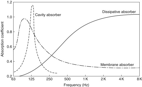
Often membrane absorbers are combined with cavity absorbers to extend their range. Some commercial modular absorbers also make use of such techniques and, by using a range of materials/membranes/cavities, can provide a wide frequency range of operation within a standard size format. Figure 29.13 illustrates general characteristics of membrane, cavity, and dissipative/porous absorbers.
Figure 29.13. Summary of typical absorber characteristics.
A newer type of “absorber” is the quadratic residue diffuser. This device uniformly scatters or diffuses sound striking it so that, although individual reflections are attenuated and controlled, the incident sound energy is essentially returned to the room. This process can therefore be used to provide controlled low-level reflections or reverberation enabling studios or control rooms to be designed without excessive absorption or subjective oppressiveness that often occurs when trying to control room reflections and resonances. When designing a studio or control room, the various absorptive mechanisms described earlier are taken into account and combined to produce a uniform absorption/frequency characteristic, that is, reverberation time.
29.3.4. Reverberation and Reflection
Reverberation times can be calculated using the following simple Sabine formula:
![]() where A is the total sound absorption in m2, which is computed by multiplying each room surface by its sound absorption coefficient and summing these to give the total
absorption present, or
where A is the total sound absorption in m2, which is computed by multiplying each room surface by its sound absorption coefficient and summing these to give the total
absorption present, or
![]() where
where
![]() is the average absorption coefficient.
is the average absorption coefficient.
In acoustically dead rooms, the following Eyring formula should be used:
![]() where V is the volume of the room in m3 and M is an air absorption constant.
where V is the volume of the room in m3 and M is an air absorption constant.
Achieving a uniform room reverberation time (absorption) characteristic does not necessarily ensure good acoustics; the effect and control of specific reflections must also be fully taken into account. For example, strong reflections can strongly interfere with the recorded or perceived live sound, causing both tonal colorations and large frequency response irregularities. Such reflections can be caused by poorly treated room surfaces, by large areas of glazing, by off doors, or by large pieces of studio equipment including the mixing console itself.
Figure 29.14 illustrates the effect well, being a frequency response plot of a monitor loudspeaker (with a normally very flat response characteristic) mounted near to a reflective side wall.
Figure 29.14. Frequency response plot of a monitor loudspeaker mounted adjacent to wall.

Apart from causing gross frequency response irregularities and colorations, side wall reflections also severely interfere with stereo imaging precision and clarity. Modern studio designs go to considerable lengths to avoid such problems by either building the monitor loudspeakers into, but decoupled from, the structure and treating adjacent areas with highly absorbing material or by locating the monitors well away from the room walls and again treating any local surfaces. Near field monitoring overcomes many of these problems, but reflections from the mixing console itself can produce comb filtering irregularities. However, hoods or careful design of console-speaker geometry/layout can be used to help overcome this.
The so-called live end dead end approach to control room design uses the aforementioned techniques to create a reflection-free zone, enabling sound to be heard directly from the monitors with a distinct time gap before any room reflections arrive at the mixing or prime listening position. Furthermore, such reflections that do occur are carefully controlled to ensure that they do not cause sound colorations nor affect the stereo image, but just add an acoustic liveliness or low-level reverberant sound field, which acts to reduce listening fatigue and provide better envelopment within the sound field.