
Chapter 18. Digital Audio Interfaces
18.1. Digital Audio Interfaces
Many of the advantages of digital signal processing are lost if signals are repeatedly converted back and forth between the digital and analogue domain. So that the number of conversions could be kept to a minimum, as early as the 1970s, manufacturers started to introduce proprietary digital interface standards enabling various pieces of digital audio hardware to pass digital audio information directly without recourse to standard analogue connections. Unfortunately, each manufacturer adopted its own standard, and the Sony digital interface (SDIF) and the Mitsubishi interface both bear witness to this early epoch in digital audio technology when compatibility was very poor between different pieces of equipment. It wasn’t long before customers were demanding an industry-standard interface so that they could “mix and match” equipment from different manufacturers to suit their own particular requirements. This pressure led to the introduction of widespread, standard interfaces for the connection of both consumer and professional digital audio equipment.
The requirements for standardizing a digital interface go beyond those for an analogue interface in that, as well as defining the voltage levels and connector style, it is necessary to define the data format the interface will employ. The two digital audio interface standards described here are:
- The two-channel, serial, balanced, professional interface (the so-called AES/EBU or IEC958 type 1 interface).
- The two-channel, serial, unbalanced, consumer interface (the so-called SPDIF or IEC958 type 2 interface).
In fact, both these interfaces are very similar, with variations being more due to electrical differences than between differences in data format.
18.1.1. AES/EBU or IEC958 Type 1 Interface
This electrically balanced version of the standard digital interface was originally defined in documents produced by the Audio Engineering Society (AES) and the European Broadcasting Union (EBU) and is, consequently, usually referred to as the AES/EBU standard. This is the standard adopted mainly by professional and broadcast installations. Mechanically, this interface employs the ubiquitous XLR connector and adopts normal convention for female and male versions for inputs and outputs, respectively. Electrically, pin 1 is specified as shield and pins 2 and 3 for balanced signal. One of the advantages of the digital audio interface over its analogue predecessor is that polarity is not important, so it is not necessary to specify which pin of 2 and 3 is “hot.” The balanced signal is intended to be carried by balanced, twisted-pair, and screen microphone-style cable and voltage levels are allowed to be between 3 and 8 V pk-pk (EMF, measured differentially). Both inputs and outputs are specified as transformer coupled and earth free. The output impedance of the interface is defined as 110 ohms, and a standard input must always terminate in 110 ohms. A drawing for the electrical standard for this interface is given in Figure 18.1.
Figure 18.1. AES/EBU interface.

18.1.2. The SPDIF or IEC985 Type 2 Interface
This consumer version of the two-channel, serial digital interface is very different electrically from the AES/EBU interface described earlier. It is a 75-ohm, matched termination interface intended for use with coaxial cable. It therefore has more in common with an analogue video signal interface than with any analogue audio counterpart. Mechanically the connector style recommended for the SPDIF interface is RCA style phono with sockets always being of the isolated type. Voltage levels are defined as 1 V pk-pk when unterminated. Transformer coupling is by no means always used with this interface but it is recommended on at least one end. Figure 18.2 is a drawing of a common implementation of the SPDIF interface.
Figure 18.2. SPDIF interface.

18.1.3. Data
Despite the very considerable electrical differences between the AES/EBU interface and the SPDIF interface, their data formats are very similar. Both interfaces have capacity for the real-time communication of 20 bits of stereo audio information at sampling rates between 32 and 48 kHz, as well as provision for extra information, which may indicate to the receiving device various important parameters about the data being transferred (such as whether preemphasis was used on the original analogue signal prior to digitization). There is also a small overhead for limited error checking and for synchronization.
Some of the earlier digital–audio interfaces such as Sony’s SDIF and the Mitsubishi interface sent digital audio data and synchronizing data clocks on separate wires. Such standards obviously require multicore cable and multiway connectors, which looked completely different from any analogue interface that had gone before. The intention of the designers of the AES/EBU and SPDIF interfaces was to create standards that created as little “culture shock” as possible in both the professional and the consumer markets and therefore they chose connector styles that were both readily available and operationally convenient. This obviously ruled out the use of multicore and multiway connectors and resulted in the use of a digital coding scheme that buries the digital synchronizing signals in with the data signal. Such a code is known as “serial and self-clocking.” The type of code adopted for AES/EBU and SPDIF is biphase mark coding. This scheme is sometimes known as Manchester code and it is the same type of self-clocking, serial code used for SMPTE and EBU time code. Put at its simplest, such a code represents the “ones and noughts” of a digital signal by two different frequencies where frequency Fn represents a zero and 2Fn represents a one. Such a signal eliminates almost all DC content, enabling it to be transformer coupled, and also allows for phase inversion since it is only a frequency (and not its phase) that needs to be detected. The resulting signal has much in common with an analogue FM signal and since the two frequencies are harmonically related (an octave apart), it is a simple matter to extract the bit clock from the composite incoming data stream.
In data format terms the digital audio signal is divided into frames. Each digital audio frame contains a complete digital audio sample for both left and right channels. If 48-kHz sampling is used, it is obvious that the 48 thousand frames pass over the link in every second, leading to a final baud rate of 3.072 Mbit/s. If 44.1-kHz sampling is employed, 44 thousand one-hundred frames are transmitted every second, leading to a final baud rate of 2.8224 Mbit/s. The lowest allowable transfer rate is 2.084 Mbit/s when 32 kHz is used. Just as each complete frame contains a left and right channel sample, so each frame may be further divided into individual audio samples known as subframes. A diagram of a complete frame consisting of two subframes is given in Figure 18.3.
Figure 18.3. Digital audio data format.
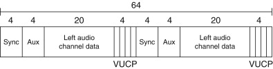
It is extremely important that any piece of equipment receiving the digital audio signal, as shown in Figure 18.3, must know where the boundaries between frames and subframes lie. That is the purpose of the “sync preamble” section of each frame and subframe. The sync preamble section of the digital audio signal differs from all other data sent over the digital interface in that it violates the rules of a biphase mark encoded signal. In terms of the FM analogy given earlier you can think of the sync preamble as containing a third nonharmonically related frequency, which, when detected, establishes the start of each subframe. There exists a family of three slightly different sync preambles, one to mark the beginning of a left sample subframe and another to mark the start of the right channel subframe. The third sync preamble pattern is used only once every 192 frames (or once every 4 ms in the case of 48-kHz sampling) and is used to establish a 192 bit repeating pattern to the channel-status bit labeled C in Figure 18.3.
The 192 bit repeat pattern of the C bit builds up into a table of 24 bytes of channel-status information for the transmitted signal. It is in this one bit of data every subframe that the difference between the AES/EBU interface data format and the SPDIF data format is at its most significant. The channel status bits in both the AES/EBU format and SPDIF format communicate to the receiving device such important parameters as sample rate, whether frequency preemphasis was used on the recording, and so on. Channel-status data are normally the most troublesome aspect of practical interfacing using the SPDIF and AES/EBU interface, especially where users attempt to mix the two interface standards. This is because the usage of channel status in consumer and professional equipment is almost entirely different. It must be understood that the AES/EBU interface and the SPDIF interface are thus strictly incompatible in data format terms and the only correct way to transfer data from SPDIF to AES/EBU and AES/EBU to SPDIF is through a properly designed format converter that will decode and recode digital audio data to the appropriate standard.
Other features of the data format remain pretty constant across the two interface standards. The validity bit, labeled V in Figure 18.3, is set to 0 every subframes if the signal over the link is suitable for conversion to an analogue signal. The user bit, labeled U, has a multiplicity of uses defined by particular users and manufacturers. It is used most often over the domestic SPDIF interface. The parity bit, labeled P, is set such that the number of ones in a subframe is always even. It may be used to detect individual bit errors but not conceal them.
It’s important to point out that both the AES/EBU interface and its SPDIF brother are designed to be used in an error-free environment. Errors are not expected over digital links and there is no way of correcting for them.
18.1.4. Practical Digital Audio Interface
There are many ways of constructing a digital audio interface, and variations abound from different manufacturers. Probably the simplest consists of an HC family inverter IC, biased at its midpoint with a feedback resistor and protected with diodes across the input to prevent damage from static or overvoltage conditions. (About the only real merit of this circuit is simplicity!) Transformer coupling is infinitely preferred. Happily, while analogue audio transformers are complex and expensive items, digital audio—containing no DC component and very little low-frequency component—can be coupled via transformers, which are tiny and inexpensive! So, it represents a false economy indeed to omit them in the design of digital interfaces. Data-bus isolators manufactured by Newport are very suitable. Two or four transformers are contained within one IC-style package. Each transformer costs about $2—a long way from the $20 or so required for analogue transformers. Remember too that “in digits” only, one transformer is required to couple both channels of the stereo signal. You’ll notice, looking at the circuit diagrams (Figure 18.4), RS422 (RS485) receiver-chips buffer and reslice digital audio data. The SN75173J is a quad receiver in a single 16 pin package costing a few dollars. The part has the added advantage that, to adapt the interface between SPDIF and AES, all that is required is to change the value of the terminating resistor on the secondary side of the input transformer. SPDIF digital output can be derived by inverters driving in tandem. If AES/EBU output is required, it is best performed by an RS422 driver IC.
Figure 18.4. Practical digital audio interfaces.

18.1.5. TOSlink Optical Interface
In many ways an optical link seems to be the ideal solution for joining two pieces of digital audio equipment together. Obviously a link that has no electrical contact cannot introduce ground-loop, hum problems. Also, because the bandwidth of an optical link is so high, it would appear from a superficial inspection that an optical link would provide the very fastest (and therefore “cleanest”) signal path possible. However, the optical TOSLink is widely regarded as sounding a little less crisp than its coaxial, electrical counterpart. There are a number of possible reasons for this. In the first place, the speed of the link is compromised by the relatively slow light-emitting diode transmitter and phototransistor receiver housed within the connector shells. Second, inexpensive optical fibers, which allow the optical signal more than one direct path between transmitter and receiver (the technical term is multimodes), cause a temporal smearing of the audio pulses, resulting in an effect known as modal dispersion. This can cause a degree of timing instability in digital audio circuits (jitter) and can affect sound quality. The only advantage the optical link confers, therefore, is its inherent freedom from ground path-induced interference signals such as hum and RF noise. Yet at digital audio frequencies, ground isolation—if it is required—is obtained much better by means of a transformer. If you want to modify a piece of equipment with an optical interface to include SPDIF coaxial output, a modification is shown in Figure 18.5.
Figure 18.5. Optical digital audio interface and adaptation to coaxial SPDIF.

18.1.6. Transmission of AES3-Formatted Data by Unbalanced Coaxial Cable
In October 1995, the AES produced an information document (AES-3id-1995) relating to the transmission of digital audio information (utilizing the professional data format) over an electrical interface that has much in common with the interconnection standards employed in analogue video. Limitations of AES data traveling on twisted pairs and terminated in XLRs include poor RF radiation performance and a limitation of maximum transmission distance to 100 m. The proposed unbalanced interface is suitable for transmission distances of up to 1000 m. Furthermore, by a prudent choice of impedance and voltage operating level, coupled with a sensible specification of minimum rise time, the signal is suitable for routing through existing analogue video cables, switchers, and distribution amplifiers.
The salient parts of the signal and interface specification are given in Table 18.1.
Table 18.1 Salient parts of the signal and interface specification.
| General | |
|---|---|
| Transmission data format | Electrically equivalent to AES |
| Impedance | 75 ohms |
| Mechanical | BNC connector |
| Signal characteristics | 1 V, measured when terminated |
| Output voltage | in 75 ohms |
| DC offset | <50 mV |
| Rise/fall time | 30 to 44 nS |
| Bit width (at 48 kHz) | 162.8 nS |
18.2. MADI (AES10–1991) Serial Multichannel Audio Digital Interface
The MADI standard is a serial transmission format for multichannel linearly represented PCM audio data. The specification covers transmission of 56, mono, 24-bit resolution channels of audio data with a common sampling frequency in the range of 32 to 48 kHz.Perhaps this is conceived more easily of in terms of 28 stereo “AES” audio channels (i.e., of AES3–1985 data) traveling on a common bearer, as illustrated in Figure 18.6. The MADI standard is not a “networking” standard; in other words, it only supports point-to-point interconnections.
Figure 18.6. Data structure of MADI, multichannel audio interface.

18.2.1. Data Format
The MADI serial data stream is organized into frames that consist of 56 channels (numbered 0–55). These channels are consecutive within the frame, and audio data remain, just as it is in the original digital audio interface, in linearly coded, 2’s-complement form, although this is scrambled as described later. The frame format is illustrated in Figure 18.6. Each channel “packet” consists of 32 bits (as also shown in Figure 18.6), in which 24 are allocated to audio data (or possibly nonaudio data if the nonvalid flag is invoked) and 4 bits for the validity (V), user (U), channel status (C), and parity (P) bits as they are used in the AES3–1985 standard audio interface. In this manner the structure and data within contributing dual-channel AES bit streams can be preserved intact when traveling in the MADI multichannel bit stream. The remaining 4 bits per channel (called, confusingly, mode bits) are used for frame synchronization on the MADI interface and for preserving information concerning A/B preambles and start of channel-status block within each of the contributing audio channels.
18.2.2. Scrambling and Synchronization
Serial data are transmitted over the MADI link in a polarity-insensitive (NRZI) form. However, before data are sent, they are subjected to a 4- to 5-bit encoding, as defined in Table 18.2. MADI has a rather unusual synchronization scheme in order to keep transmitter and receiver in step. The standard specifies that the transmitter inserts a special synchronizing sequence (1100010001) at least once per frame. Note that this sequence cannot be derived from data, as specified in Table 18.2. Unusually, this sync signal need not appear between every frame, as Figure 18.6 illustrates. This sync signal is simply repeated wherever required in order to regulate the final data rate of 100 megabits/second specified in the standard.
Table 18.2 Input and output data sequence.
| Input data sequence | Output data sequence |
|---|---|
| 0000 | 11110 |
| 0001 | 01001 |
| 0010 | 10100 |
| 0011 | 10101 |
| 0100 | 01010 |
| 0101 | 01011 |
| 0110 | 01110 |
| 0111 | 01111 |
| 1000 | 10010 |
| 1001 | 10011 |
| 1010 | 10110 |
| 1011 | 10111 |
| 1100 | 11010 |
| 1101 | 11011 |
| 1110 | 11100 |
| 1111 | 11101 |
18.2.3. Electrical Format
MADI travels on a coaxial cable interface with a characteristic impedance of 75 ohms. Video-style BNC connectors are specified. Because the signal output is practically DC free, it may be AC coupled and must sit around 0 V±100 mV. This signal is specified to have a peak-to-peak amplitude of 300–600 mV when terminated—this choice of amplitude being determined by the practical consideration that the signal could be directly derived from the output of an ECL gate.
18.2.4. Fiber-Optic Format
Oddly, the MADI standard did not define a fiber implementation, despite the fact that the copper implementation was based on a widely used fiber interface known as FDDI (ISO 9314). It is this standard, which predates the MADI, that specified the 4- to 5-bit mapping defined in Table 18.2! This lack of standardization has resulted in a rather disorganized situation regarding MADI over fiber. The AES’s own admission is simply that “any fiber-system could be used for MADI as long as the basic bandwidth and data-rate can be supported … However, adoption of a common implementation would be advantageous.”