
Project 5: Telematic Breath
In our fifth project, we will sense and re-create or “broadcast” a breath or gentle breeze from one location to another using a simple wind sensor and a small fan. Breathe on the sensor and the fan will spin at a speed that correlates to the force of your breath. In this way, applying the data from an analog sensor to the speed of a fan will provide a very tangible experience of transmitting data from one source to another.
Hooking It Up
While the hardware is a little more complex than previous projects, it's not really all that bad, with a total of four components. We have specified a very particular sensor and fan at the beginning of this chapter to complete this project, although just about any analog sensor could be used in place of the wind sensor and about any other DC fan, motor, solenoid, or other actuator could be used to substitute the fan. Likewise you might change out the transistor for another switching device like a relay or MOSFET, detailed later in Chapters 11 and 12.
This particular wind sensor is a low-cost thermal anemometer developed by Paul Badger at Modern Device to measure wind speed. Specifically, it measures the electricity needed to maintain a specific temperature on a heating element as the wind changes. This sensor is remarkably sensitive and can detect the slightest breath. We will couple this with a fan to re-create the wind speed input by controlling the speed of the fan through PWM.
The fan we chose will run on +5v DC, but it exceeds the current available to the Arduino's output pins, so to power it safely, we need to use a small transistor to switch the bigger load. The transistor we are using is the 2N3904, although the 2N2222 is pin compatible and you could even substitute any of a number of other similar devices. The 2N3904 has 3 pins labeled e, b, and c—for emitter, base, and collector respectively. These names refer to what each pin does: emitter is connected to ground; collector to the negative side of the load, in this case the black wire on the fan; and base connects to a series resistor and to the PWM pin on the Arduino.
It is possible to use a higher voltage fan, say +12v DC, using a transistor to switch it on and off. To do this you need to connect a higher voltage power supply into your Arduino and instead of connecting the positive or red wire to +5v, you would connect it to a pin on the Arduino interface board labeled Vin. Just be sure to be careful as you wire up the circuit shown in Figures 6-3 and 6-4, taking it slow and double-checking everything to make sure you get the pins correct on the sensor and the transistor, and you will be fine.
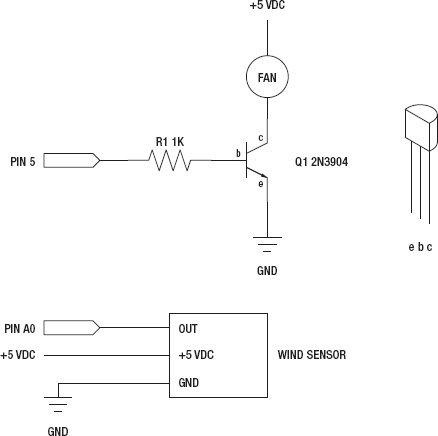
Figure 6-3. Telematic Breath schematic
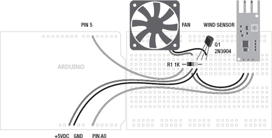
Figure 6-4. Telematic Breath illustration
Uploading the Source Code
After the crazy source code in the last chapter, this sketch will seem tame in comparison. Although while there is not much length to the code, there are a lot of new things going on that we will spend the rest of the chapter trying to explain. So let's get the circuit wired up, upload the source code in Listing 6-1, and see what it does.
Listing 6-1. Telematic Breath Source Code
const int fanPin = 5;

const int sensorPin = A0;


const int minReading = 25;

const int maxReading = 400;

const int fanStart = 100;


int analogValue = 0;


void setup() {

  Serial.begin(9600);

  }


void loop() {

  analogValue = analogRead(sensorPin);

  analogValue = constrain(analogValue, minReading, maxReading);

  analogValue = map(analogValue, minReading, maxReading, 0, 255);
  Serial.print("analog value = " );

  Serial.println(analogValue, DEC);


  if ((analogValue > minReading) && (analogValue < fanStart))

  analogWrite(fanPin, fanStart);

  else analogWrite(fanPin, analogValue);


  delay(250);

}
Source Code Summary
Like nearly all of our sketches, we begin this one with a declaration of variables for the pins that we will use, giving them descriptive names. In this case, fanPin and sensorPin.
const int fanPin = 5;

const int sensorPin = A0;
Our next block of variables pertain to some general thresholds that relate to our sensor readings and what it takes to get the fan spinning.
const int minReading = 25;

const int maxReading = 400;

const int fanStart = 100;
The first variable minReading can be adjusted to reflect the minimum reading that our sensor is providing. Likewise, maxReading is used for the same purpose on the other end of the spectrum. This is, after all, a telematic breath, not telematic gale-force wind. To make the sensor even more sensitive, you might try a smaller value for maxReading, like 200. The last variable, fanStart, is the minimum value that it takes to get our particular fan up and spinning. Yours may be different.
int analogValue = 0;
Our last variable is the container we will use to store and manipulate our analog value obtained from reading our analog input pin.
void setup() {

  Serial.begin(9600);

}
The setup() function is a little sparse in this sketch. I think I can hear you now: “Hey, wait, isn't something missing?” The short answer is not really, because the analog functions make use of very specific hardware in the Arduino microcontroller, there is no need to set them up using the pinMode() function inside our setup() function. If we try to send an analog signal to a pin that isn't made for it, it simply won't work exactly as expected. So then all we are left with is a function that begins a communication protocol that we can use to let the Arduino talk to us.
analogValue = analogRead(sensorPin);

analogValue = constrain(analogValue, minReading, maxReading);

analogValue = map(analogValue, minReading, maxReading, 0, 255);
The first three lines of the loop() function are where the magic happens in this sketch. The first line obtains a numerical value from the analog input pin correlating to the voltage our sensor is putting out, which should indicate a general presence of a breath. The second line lobs off unusable values at either end of the spectrum that don't really work for us. In other words, this line limits our activity to the “sweet spot” of the sensor, making it as sensitive as we can get it to a gentle breeze. The third line takes this larger value and remaps it to a more useable range for output to our fan.
Serial.print("analog value = " );

Serial.println(analogValue, DEC);
These two lines can be used to see what values we are working with using something called the Serial Monitor, explained in more detail later in this chapter. Seeing these values is helpful in adjusting the thresholds defined at the beginning of the sketch.
if (analogValue > minReading && analogValue < fanStart)

analogWrite(fanPin, fanStart);

else analogWrite(fanPin, analogValue);
Now we reach the business end of the sketch—the part that actually does something. Our fan needs a little kick to get it going at first, so the first line checks to see if we have an analog value that we should do something with, but that might be too low for the fan to work with. In our case, we found that the value 100 is about the lowest number to guarantee that the fan would spin. So if that's true, we will send the minimum number to start the fan out to the output pin.
Otherwise, if the value is greater than or less than our fanStart and minReading values, we will send that value straight out to the output pin. If it's a small number, the fan will most likely not spin. If it's a bigger number, it will spin with greater speed up until it hits the ceiling at 255, which is full on.
delay(250);
Finally, our last line of code ends with a simple delay() just to slow things down some. Basically, it takes a little bit of time to get the fan up to speed, so a quarter-second pause is good for that. Now what does it all mean?