Prototyping
Prototyping is a way to quickly realize a circuit and to see if it will work or not. By prototyping a thing, we can build something without spending a lot of time and money wiring everything up from scratch. This is great for focusing our efforts and our ideas rather than getting lost in soldering wires from one component to another. One of the best things that we can use to help make prototyping even easier is a breadboard.
Breadboards
Historically, amateur radio builders would put together circuits using wires and nails quite literally on cutting boards for bread. Today, we use the solderless breadboard, shown in Figure 12-12, to quickly prototype a circuit.

Figure 12-12. A solderless breadboard
This image shows one of the currently popular breadboards with a clear plastic casing. On the outside there are about 244 little square holes in the face of the breadboard. Inside, you can see rows of metal clips. When a component's metal leg is placed into the breadboard, these internal clips connect that pin to others in that row. It can be a little tricky to understand exactly how these connections are made, so Figure 12-13 illustrates the hole pattern on the face of the board as well as the internal connection inside of it.
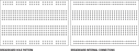
Figure 12-13. Breadboard internal connections
In this type of breadboard, two, long, power busses on both sides of the breadboard are useful for providing a + and − power supply rail that runs along the length of the board. On either side of a channel that runs down the center of the board are two rows of holes where each row of five holes are connected to each other. This center divider keeps these two sides separate and provides a place for integrated circuits that typically have two rows of pins to be plugged into the board and still be connected to other devices without inadvertently connecting the two sides of the IC together. Keep in mind that any pin inserted into one of these adjacent five positions will be connected to one another inside of the breadboard.
Now, to get a better sense for how can we use the breadboard to prototype a basic circuit, let's try one out. Figure 12-14 takes our basic lamp circuit and changes out a few of the components.
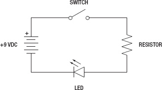
Figure 12-14. Basic LED circuit schematic
In this circuit, we have replaced the incandescent lamp with a light-emitting diode and the necessary current limiting resistor, but otherwise the circuit will work just the same as before. Now let's look at Figure 12-15 to see what it looks like on the breadboard.
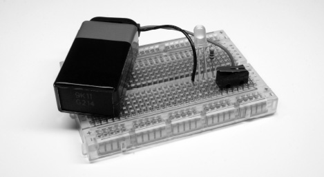
Figure 12-15. LED circuit in a breadboard
It's important to notice here that the circuit in the breadboard does not necessarily look like the schematic. That's because schematics are not meant to be a geographical map of what the circuit looks like but rather they simply show the connections that need to be made. Connecting one pin of the LED and one pin of the resistor into any of the five holes that share a connection will connect the LED to the resistor, completing that part of the circuit. Starting at the top left-hand side of the schematic, we see that the positive side of the battery connects to one side of the switch, the other side of the switch connects to the resistor, the second leg of the resistor connects to the positive or anode pin of the LED, and the negative pin or cathode of the LED connects to the negative terminal of the battery. We could place the components in this circuit in a nearly infinite number of ways, and as long as we made the same connections, then the circuit would work fine each time.
In our example, we connect the pins of each component right into the breadboard itself. If we had a more difficult circuit to build, we would need to use hookup wires to connect one point to another. These wires can either be solid, insulated wire cut to length, we find that 22-gauge works best, or male-to-male, pre-terminated jumper wires. Keep in mind though that when building a circuit on a breadboard, or changing some of the components or wiring, it's a good idea to disconnect any power source from the board, as crossing wires while the board is powered up could damage your components.
While the breadboard provides a quick and relatively painless way to prototype a circuit sometimes soldering two wires together, or parts like pin headers to breakout boards, is just unavoidable. So let's look at what soldering is and how we can make permanent connections with reasonable success.