
Project 6: Ambient Temps
This project will provide a visual indication of the ambient temperature in our immediate location by pairing a simple temperature sensor with an RGB LED. You might want to embed this project in a glass jar, a lamp, or other object. When it gets hot, our LED will fade to a deep red color; when it's cold, a deep blue color; and when the temperature is about right, the LED will change to green, with all of the colors possible between the two extremes. To make this work, we are going to need more complex color-mixing than we have done previously with seven colors. Rather than make our lives more difficult than they need to be, we will replace our RGB LED with the BlinkM MinM smart LED for this project. The BlinkM is an RGB LED, like we have previously used, that has been coupled with a small Arduino-like microcontroller with some secret software, or firmware, that has been preloaded on the device. This means that the BlinkM is capable of handling all of the color mixing for us using, at least in our example, the Hue Saturation Brightness or HSB color model shown in Figure 7-1.
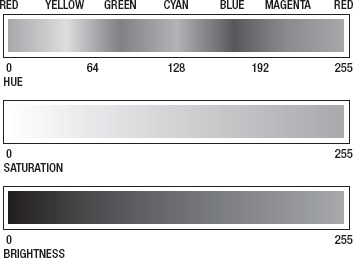
Figure 7-1. HSB color model
Again, we have black-and-white images of color models, but if you remember back to Chapter 2 where we discussed the RGB color wheel, HSB handles color values by specifying the colors hue with a value from 0 to 255, beginning with red and rotating through all the colors in the rainbow until we get back to red on the other end. We can also specify a color's saturation (the vividness of the color) and the color's brightness (the lightness or darkness of the color). This will work nicely in our project code because we can keep the saturation and brightness at the same level while fading through multiple colors with red at 0 on one end and blue at 170 on the other.
Hooking It Up
This basic circuit combines the BlinkM MinM smart LED with the TMP36 temperature sensor that comes in a package similar to our transistor from the last project, but with a different pin connection. It's still super-easy to hook up and, once connected to +5 volts and ground, the output pin will provide a linear reading that corresponds to the temperature measured in Celsius, as shown in Figure 7-2.

Figure 7-2. TMP36 output voltage versus temperature Celsius
The TMP36 has a 0.5v offset that we will have to compensate for, but because of the linearity of the output signal only a little math is needed to determine the ambient temperature to within ? 2? Celsius. There are many other temperature sensors like these that we could use or we could add additional sensors, like ones for measuring humidity or barometric pressure, but we are going to keep it simple for this project. You might also want a little more power out of your LEDs, so you could substitute one of the other varieties of the BlinkM, even connecting a MaxM to an entire string of LEDs. For more information and to download the data sheet and quick-start guide, check out ThingM's web site at http://thingm.com/products/blinkm/. Now, let's connect our project, as shown in Figures 7-3 and 7-4.

Figure 7-3. Ambient Temps schematic

Figure 7-4. Ambient Temps illustration
Uploading the Source Code
This sketch for this project will serve as a good example of how to compartmentalize our code by writing and using custom functions, which a good part of this chapter is dedicated to. There are three main parts to this code: reading and calculating the current temperature; mapping that reading to a usable HSB color value; and then sending the appropriate commands to the BlinkM to get it to respond with the color that we want. Let's get this project wired up and the source code in Listing 7-3 uploaded, and continue our discussion from there.
Listing 7-3. Ambient Temps Source Code
#include <Wire.h>


const int blinkM = 0x09;

const int temperaturePin = A0;


const boolean degreesF = true;


const int hot = 100;

const int cold = 40;

const int hotColor = 0;

const int coldColor = 170;

const int brightness = 255;


void setup() {

  Wire.begin();

  stopScript(blinkM);

  setFadeSpeed(blinkM, 1);

}
void loop() {

  int hue = map(temperature(), hot, cold, hotColor, coldColor);

  hue = constrain(hue, hotColor, coldColor);

  fadeToHSB(blinkM, hue, 255, brightness);

  delay(10000);

}


float temperature() {

  float voltage = (analogRead(temperaturePin) / 1024.0) * 5.0;

  float celsius = (voltage - 0.5) * 100.0;

  float fahrenheit = (celsius * 1.8) + 32.0;

  if (degreesF == true) return fahrenheit;

  else return celsius;

}


void stopScript(byte address) {

  Wire.beginTransmission(address);

  Wire.write('o'),

  Wire.endTransmission();

}


void setFadeSpeed(byte address, byte fadespeed) {

  Wire.beginTransmission(address);

  Wire.write('f'),

  Wire.write(fadespeed);

  Wire.endTransmission();

}


void fadeToHSB(byte address, byte hue, byte saturation, byte brightness) {

  Wire.beginTransmission(address);

  Wire.write('h'),

  Wire.write(hue);

  Wire.write(saturation);

  Wire.write(brightness);

  Wire.endTransmission();

}
Source Code Summary
The first line of our sketch is necessary for using the Wire library that will allow the Arduino and BlinkM to talk to each other using a protocol called I2C, discussed at length in Chapter 10. Since we don't need to worry about that for now, let's jump to the variable declarations and see what they do.
const int blinkM = 0x09;

const int temperaturePin = A0;
These first two lines set up the locations for the BlinkM and our temperature sensor. The first is an address to identify which BlinkM to talk to. This value comes as the default and if we only use one BlinkM, will not need to be changed. The second line establishes that our temperature sensor is connected to pin A0.
const boolean degreesF = true;


const int hot = 100;

const int cold = 40;

const int hotColor = 0;

const int coldColor = 170;

const int brightness = 255;
This block of code declares the variables that can be used to configure various settings in our sketch. The first of these turns on Fahrenheit temperatures using true and by using false will revert to Celsius temperatures. The variable hot and cold allows us to specify what we think is hot and cold for our location—hot in London is perhaps not the same as hot in Phoenix. With these values set, any temperature below the cold limit will remain blue while any temperature hotter than the hot value will stay red. Since it is entirely possible that hot being red and cold being blue might be too obvious for you, you can change the values for hotColor and coldColor to establish the two extreme colors in HSB values. Finally, the BlinkM can be insanely bright, so we have an option to specify a different brightness level that will dim the LED without changing its color.
Wire.begin();

stopScript(blinkM);

setFadeSpeed(blinkM, 1);
Because we are using several new functions in our sketch, the code in our setup() function is a little sparse. The first line starts the communication protocol that we will use for the BlinkM. Again, this will be covered in greater detail later in this book. The stopScript() and setFadeSpeed() functions are two of our custom functions used for setting options in the BlinkM. We'll talk about these in a moment, so let's move on to the code in our loop() function.
int hue = map(temperature(), hot, cold, hotColor, coldColor);
We begin here with mapping whatever value is returned from the temperature() function, as defined by the hot and cold endpoints, to whatever hue value will correspond to that temperature, as defined by the hotColor and coldColor variables. Because it is possible for these values to end up outside of this range, we will also need the constrain() function:
hue = constrain(hue, hotColor, coldColor);
This line will keep the LED from suddenly turning pink if the values were to get a little wonky (technically speaking). Once we have our hue value established, we need to send this out to our BlinkM as we did in the following:
fadeToHSB(blinkM, hue, 255, brightness);

delay(10000);
The function fadeToHSB() will send a command to the BlinkM, telling it to fade to whatever color is specified in the hue that we just worked out; a saturation of 255, although you could play with this number; and the brightness that we established at the beginning of our sketch. We then delay for 10 seconds just to keep the LED from flickering because of small fluctuations in temperature. Now let's look at our functions.
float temperature() {

  float voltage = (analogRead(temperaturePin) / 1024.0) * 5.0;

  float celsius = (voltage - 0.5) * 100.0;

  float fahrenheit = (celsius * 1.8) + 32.0;

  if (degreesF == true) return fahrenheit;

  else return celsius;

}
The temperature() function is a different data type than what we normally see, so it can return a value that is of the float data type. The first line of this function reads the temperature sensor and converts the values from a range of 0–1024 to a voltage from 0 to 5 volts. To obtain the degrees in Celsius we need to offset 0.5v for the TMP36, as described in the device's data sheet, and then multiply this value by 100.0, as shown in Figure 7-2. Once we have the degrees Celsius, we can convert this value to Fahrenheit by multiplying 1.8 and adding 32. The function ends by checking whether or not we wanted degrees in Fahrenheit and returns the appropriate temperature value.
Our next three functions are used to send specific commands to the BlinkM to change its default settings and output the correct color. The specific commands can be found in the BlinkM data sheet available from ThingM's web site. Our first function, stopScript(), disables the default startup script by sending it the character “o” as follows:
void stopScript(byte address) {

  Wire.beginTransmission(address);

  Wire.write('o'),

  Wire.endTransmission();

}
Our next function is not entirely necessary, but it sets the BlinkM to its slowest fade speed. Each time we tell the BlinkM to change color, it will fade from its current color to the new one. This is a nice little feature and by slowing it down even more, we help make our device more ambient, slowly changing colors in the background. The setFadeSpeed() function will send the BlinkM the character “f” followed by the fade speed with a possible range of 1–255, with 1 being the slowest and 255 being instantaneous. The default speed is 15.
void setFadeSpeed(byte address, byte fadespeed) {

  Wire.beginTransmission(address);

  Wire.write('f'),

  Wire.write(fadespeed);

  Wire.endTransmission();

}
The last function, fadeToHSB(), is what makes things so easy for us and is the reason for choosing the BlinkM over the standard RGB LED.
void fadeToHSB(byte address, byte hue, byte saturation, byte brightness) {

  Wire.beginTransmission(address);

  Wire.write('h'),

  Wire.write(hue);

  Wire.write(saturation);

  Wire.write(brightness);

  Wire.endTransmission();

}
Using this function, we send it four pieces of information: the BlinkM's address followed by the values for hue, saturation, and brightness. The function will send the character “h” to the BlinkM followed by the HSB values, and the BlinkM will work out the math for fading from one color to another.
Well, that was a fairly lengthy overview of how the code works, but we should back up now and look at what's involved in writing and working with functions like those in our project example.