Build More Projects
The first thing to do, of course, with your newfound Arduino skills is build more projects! We couldn't cover every project idea in this one book and I tried to keep what we did talk about to the very basics. So, here are a few things that I would have loved to have previously discussed in more depth that you might be able to try out.
Bonus Project 1: Make Something Tweet
Remember that Arduino Ethernet Shield I suggested was a good idea when we learned how to log data on an SD card? Well, if you have this shield, or maybe one of the new boards called the Arduino Ethernet, then you can make your next project tweet. Maybe you're inspired by the functionality of the Botanicalls shown in Chapter 1, but rather than knowing that your plants need water, you want to know instead when the coffee in the office is ready or the beer keg has been emptied, maybe you really need to keep track of the irregular hours that your cat (or teenager?) enters and leaves the house, or maybe you just want to display an updated status of your whereabouts on a display in your office no matter where you are.
What's Needed
To get started tweeting with the Arduino, we need to use a few libraries and the appropriate hardware on the Arduino, along with a Twitter account and a little utility that was written especially for this that can be found at www.arduino.cc/playground/Code/TwitterLibrary. To begin, we will need the Arduino Ethernet Shield, as shown in Figure 11-1.
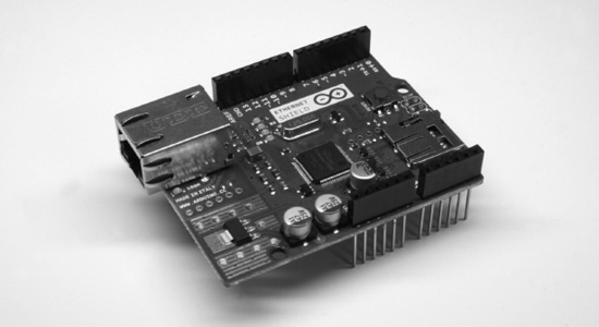
Figure 11-1. Arduino Ethernet Shield
With that in hand, we need to plug it into the Arduino and connect it to our network using an Ethernet cable. Next up, we need to install two of the four Arduino libraries, available from the earlier link, used in this application: Twitter and EthernetDNS. The other two libraries, SPI and Ethernet, come with Arduino versions 0019 and newer. Next up, we can start with the example sketch, SimplePost, included with the Twitter library and shown in Figure 11-2.
Figure 11-2. Twitter library example
When the libraries are placed correctly in the libraries folder, the example sketch will show up in the File ![]() Examples
Examples ![]() Twitter menu, as shown. If not, you might need to hunt down the correct library folder.
Twitter menu, as shown. If not, you might need to hunt down the correct library folder.
![]() Note You might have noticed that we're using the 0022 version of Arduino in Figure 11-2. At the time of this writing, the Twitter library did not play nice with the 1.0 beta but the Arduino developers are working hard and I'm sure this will be fixed by the time this book is published.
Note You might have noticed that we're using the 0022 version of Arduino in Figure 11-2. At the time of this writing, the Twitter library did not play nice with the 1.0 beta but the Arduino developers are working hard and I'm sure this will be fixed by the time this book is published.
Making It Work
With our sketch open, we need to set three things to make this work. The first thing to set is the MAC address of the Ethernet adapter. This is usually printed on a little label on the bottom of the Ethernet shield and entered in the array mac[]. Second, we need to find an available IP address on our network and enter it into the array named ip[]. Finally, we need to obtain an authorization token from Twitter to be able to use its services and enter this token in the Twitter twitter() object. To obtain this token, our example sketch uses the Arduino—tweet application at http://arduino-tweet.appspot.com. With all of that in place, we can upload the sketch to the interface board and then open up the Serial Monitor to see what's going on. When everything works, we should see the tweet posted by our Arduino, as shown in Figure 11-3.
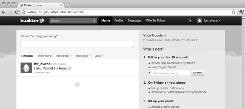
Figure 11-3. Something tweeted
Okay, so “Hello, World! I'm Arduino!” is perhaps not the most exciting thing to tweet, but it's a start right? With the right kind of sensors, I'm sure you can find something interesting to make tweet using these libraries. Or maybe instead, you can get the Arduino to display incoming tweets on an LCD or other form of display. For more ideas on what to do with the Arduino Ethernet Shield, check out the following tutorials from bildr, the modular tutorial site:
http://bildr.org/2011/06/arduino-ethernet-pin-control/

http://bildr.org/2011/06/arduino-ethernet-client/
Bonus Project 2: Make Something Move
We also didn't get a chance to talk much about making things move. We did have a look at connecting a small DC fan back in Chapter 6, and in Chapter 9 we discussed servo and stepper motors as way to make something move with fairly precise positioning. You might instead want to make something move using common and very popular DC motors. As explained in more depth in the next chapter, DC motors come with and without gearboxes and run at a variety of speeds with different current requirements. The following are three possible things that we can look for when connecting DC motors to the Arduino:
- The motor can run at variable speeds
- The motor can run at high currents
- The motor can switch directions
Of these three things—in a simple circuit that we are not throwing the kitchen sink at—we can usually do two of these at any one time. So for example, we can run a motor at high currents and at a range of speeds, but it's a little more difficult to get it to switch directions. Instead, we could have a motor change direction, but we would then need to decide whether a high current or variable speeds is more important.
The code to work with DC motors is fairly simple using a combination of digital and/or analog outputs, which we covered somewhat thoroughly in Chapters 5 and 6. The circuits, however, are a little more complex, and we won't be able to go into all the complexities here, but let's cover three simple ways to interface DC motors that illustrate the rule of variable speeds/high currents/switching directions with a general explanation on how to make each circuit work. We'll leave the specifics up to you for further exploration.
MOSFETs
The Metal Oxide Field Effect Transistor, or MOSFET, is one of the simpler components to use with DC motors along with the basic transistor shown in Figure 6-4 of Chapter 6. The following circuit in Figures 11-4 and 11-5 uses an IRL540 MOSFET, although others would work as well, to switch a motor with a load of up to about 20 amps. That's a pretty big motor! The IRL540 can also switch at a very fast rate of speed, so we can use PWM to control the speed of a motor connected in this circuit. This circuit also uses a 1N4001 diode connected to the positive and negative side of the motor to prevent any electrical surges from the motor damaging the MOSFET.
![]() Note In all of these motor circuits, we have a pin that is marked +V MOTOR. While we have connected these to our standard +5 VDC supply because our motors worked on +5 volts, you may need to connect these pins to a larger power supply, depending on the needs of your motor.
Note In all of these motor circuits, we have a pin that is marked +V MOTOR. While we have connected these to our standard +5 VDC supply because our motors worked on +5 volts, you may need to connect these pins to a larger power supply, depending on the needs of your motor.

Figure 11-4. MOSFET and DC Motor schematic
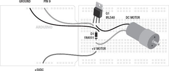
Figure 11-5. MOSFET and DC Motor illustration
When connected to pin 9 on the Arduino board, we can either control the motor digitally, meaning turn it on or off, using the digitalWrite() function or we could instead control the speed of the motor using PWM and the analogWrite() function with 0 being off and 255 being full speed forward. This high current and variable speed comes with the drawback that we can only control the motor in one direction.
H-Bridges
We have already used the SN754410 H-bridge integrated circuit in Chapter 9 to control a bipolar stepper motor, but we can also use it to control up to two DC motors, although we have only shown it with one in Figures 11-6 and 11-7. By using a couple of the Arduino's digital outputs, we can control the direction of the motor as well as its speed using one of the PWM pins. This, however, comes at the cost of the size of the motor, with the SN754410 only capable of 1-amp output capacity.

Figure 11-6. H-Bridge and DC Motor schematic
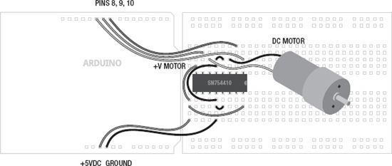
Figure 11-7. H-Bridge and DC Motor illustration
When configured as shown, pins 8 and 9 will control the direction of the motor using digital outputs and the digitalWrite() function, while pin 10 will control the motor's speed using analogWrite() with 0 being off and 255 being full speed ahead. To get a sense of how these two pins control the direction of the motor, see Table 11-1.

By writing a HIGH signal on pin 8 and a LOW signal on pin 9, then the motor will spin one direction and will reverse direction when pin 8 is LOW and pin 9 is HIGH. If both pins are LOW, then the motor will have 0 voltage and will spin freely—assuming it's not a gear motor. If both pins are set to HIGH, then current will be applied to both sides of the motor, locking the motors position just like an electronic brake.
From here, all you need to do is set the direction using pins 8 and 9, then control the speed with analogWrite() on Pin 10, and you're up and running with an H-bridge.
Relays
In this project, we will briefly look at using a mechanically switching relay to handle high currents and switch directions with a DC motor. Relays work a little like the light switches in our walls, with little metal contacts inside the switch, which are physically moved whenever the switch is activated, completing a circuit. This is done by sending a digital signal to a little magnetic coil inside the relay that activates the switch for us. In Figures 11-8 and 11-9 we are using the Axicom D2N V23105 relay with a +5v coil that can control a motor of up to 3 amps at a ridiculously high voltage of +220 volts.
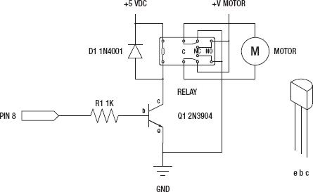
Figure 11-8. Relay and DC Motor schematic
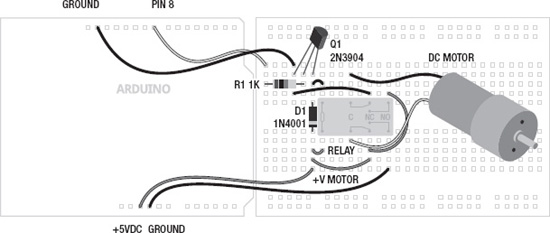
Figure 11-9. Relay and DC Motor illustration
This circuit is a little more complex, but it gives us bi-directional control of the motor using a single digital output, and we have a high amount of current to play with. Alas, this is at the cost of the ability to control the speed of the motor because the relay simply cannot switch at a very fast speed. Inside of the relay there are actually two switches with two positions each: normally open and normally closed. With the wiring as shown, when the relay is activated, the motor will be connected to the power supply in one direction and when the relay is off the motor will be connected in the opposite direction. This also means that the motor will always spin in one direction or another. This circuit doesn't quit!
While the coil of the relay is rated for +5v, I don't trust it with the microcontroller, so we've used a 2N3904 transistor to switch the relay on or off and a 1N4001 diode to protect the transistor from surges, like we did with the MOSFET. And finally, no two relays are ever really the same, so double-check the wiring for your relay before wiring this up.
That might have been a lot to take in, but the code is really simple and this brief little introduction to motors and the Arduino should be enough to send you on your way to find more information and give it a try.
Bonus Project 3: Mega-Size Something
Our final project idea isn't so much a project as it is a neat piece of hardware. Throughout this book, our projects have been written for the standard Arduino interface board, the Arduino Uno. The Uno, however, has a bigger brother called the Arduino Mega 2560, shown in Figure 11-10, and its capabilities should inspire new projects.

Figure 11-10. Arduino Mega 2560
The Mega 2560 is bigger than the little Uno in every way—it has 54 input and output pins, more than four times that of the Uno, 14 of which can be used for PWM; ten more analog inputs, for 16 total; four hardware serial ports instead of one; eight times the program memory at 256 kilobytes and four times the RAM and EEPROM space. Not only can it hold bigger sketches, it can, for example, control the speed of 14 DC motors, read from 16 different analog sensors, or even easily switch 128 LEDs with no additional hardware or tricky wiring needed. While there are always extra hardware components that can give the Uno similar levels of capabilities, the Mega 2560 doesn't need them, simplifying your wiring and your code.
Speaking of code, the Arduino Mega 2560 works pretty much just like its little brother. The pins used for I2C are in a different location and there are extra hardware serial ports, but otherwise the same code should work just fine on the Mega. The Mega is also compatible with most of the shields made for the Uno, including the Ethernet Shield, so the next time you need to blink a ton of LEDs, you might want to consider using the Arduino Mega 2560.