
2.4 PICmicro Mid-Range Family
The PICmicro line includes several different families of microprocessors. We will concentrate on the mid-range family, the PIC16F family, which has an 8-bit word size and 14-bit instructions.
2.4.1 Processor and Memory Organization
The PIC16F family has a Harvard architecture with separate data and program memories. Models in this family have up to 8,192 words of instruction memory held in flash. An instruction word is 14 bits long. Data memory is byte addressable. They may have up to 368 bytes of data memory in static random-access memory (SRAM) and 256 bytes of electrically-erasable programmable read-only memory (EEPROM) data memory.
Members of the family provide several low power features: a sleep mode, the ability to select different clock oscillators to run at different speeds, and so on. They also provide security features such as code protection and component identification locations.
2.4.2 Data Operations
Address range
The PIC16F family uses a 13-bit program counter. Different members of the family provide different amounts of instruction or data memory: 2K instructions for the low-end models, 4K for medium, and 8K for large.
Instruction space
Figure 2.18 shows the organization of the instruction space. The program counter can be loaded from a stack. The lowest addresses in memory hold the interrupt vectors. The rest of memory is divided into four pages. The low-end devices have access only to page 0; the medium-range devices have access only to pages 1 and 2; high-end devices have access to all four pages.
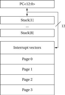
Figure 2.18 Instruction space for the PIC16F.
Data space
The PIC16F data memory is divided into four bits. Two bits of the STATUS register, RP<1:0>, select which bank is used. PIC documentation uses the term general purpose register to mean a data memory location. It also uses the term file register to refer to a location in the general-purpose register file. The lowest 32 locations of each bank contain special function registers that perform many different operations, primarily for the I/O devices. The remainder of each bank contains general-purpose registers.
Because different members of the family support different amounts of data memory, not all of the bank locations are available in all models. All models implement the special function registers in all banks. However, not all of the banks make general-purpose registers available. The low-end models provide general-purpose registers only in bank 0, the medium models banks 0 and 1, while the high-end models support general-purpose registers in all four banks.
Program counter
The 13-bit program counter is shadowed by two other registers: PCL and PCLATH. Bits PC<7:0> come from PCL and can be modified directly. Bits PC<12:8> of PC come from PCLATH which is not directly readable or writable. Writing to PCL will set the lower bits of PC to the operand value and set the high bits of PC from PCLATH.
PC stack
An 8-level stack is provided for the program counter. This stack space is in a separate address space from either the program or data memory; the stack pointer is not directly accessible. The stack is used by the subroutine CALL and RETURN/RETLW/RETFIE instructions. The stack actually operates as a circular buffer—when the stack overflows, the oldest value is overwritten.
STATUS register
STATUS is a special function register located in bank 0. It contains the status bits for the ALU, reset status, and bank select bits. A variety of instructions can affect bits in STATUS, including carry, digit carry, zero, register bank select, and indirect register bank select.
Addressing modes
PIC uses f to refer to one of the general-purpose registers in the register file. W refers to an accumulator that receives the ALU result; b refers to a bit address within a register; k refers to a literal, constant, or label.
Indirect addressing is controlled by the INDF and FSR registers. INDF is not a physical register. Any access to INDF causes an indirect load through the file select register FSR. FSR can be modified as a standard register. Reading from INDF uses the value of FSR as a pointer to the location to be accessed.
Data instructions
Figure 2.19 lists the data instructions in the PIC16F. Several different combinations of arguments are possible: ADDLW adds a literal k to the accumulator W; ADDWF adds W to the designated register f.
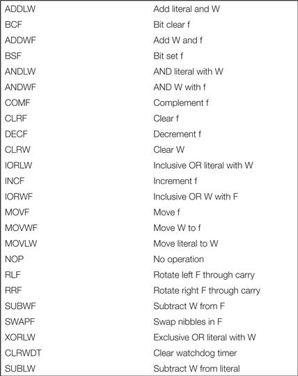
Figure 2.19 Data instructions in the PIC16F
Example 2.7 shows the code for an FIR filter on the PIC16F.
Example 2.7 FIR Filter on the PIC16F
Here is code generated for our FIR filter by the PIC MPLAB C32 compiler, along with some manually generated comments. As with the ARM, the PIC16F uses a stack frame to organize variables:
.L2:
lw $2,0($fp)
slt $2,$2,8
beq $2,$0,.L3 ; loop test---done?
nop ; fall through conditional branch here
lw $2,0($fp)
sll $2,$2,2 ; compute address of first array value
addu $3,$2,$fp
lw $2,0($fp)
sll $2,$2,2 ; compute address of second array value
addu $2,$2,$fp
lw $3,8($3) ; get first array value
lw $2,40($2) ; get second array value
mul $3,$3,$2 ; multiply
lw $2,4($fp)
addu $2,$2,$3 ; add to running sum
sw $2,4($fp) ; store result
lw $2,0($fp)
addiu $2,$2,1 ; increment loop count
sw $2,0($fp)
b .L2 ; unconditionally go back to the loop test
nop
2.4.3 Flow of Control
Jumps and branches
Figure 2.20 shows the PIC16F’s flow of control instructions. GOTO is an unconditional branch. PC<10:0> are set from the immediate value k in the instruction. PC<12:11> come from PCLATH<4:3>. Test-and-skip instructions such as INCFSZ take a register f. The f register is incremented and a skip occurs if the result is zero. This instruction also takes a one-bit d operand that determines where the incremented value of f is written: to W if d = 0 and f if d = 1. BTFSS is an example of a bit test-and-skip instruction. It takes an f register argument and a three-bit b argument specifying the bit in f to be tested. This instruction also skips if the tested bit is 1.
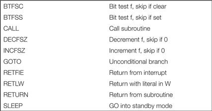
Figure 2.20 Flow of control instructions in the PIC16F.
Subroutines
Subroutines are called using the CALL instruction. The k operand provides the bottom 11 bits of the program counter while the top two come from PCLATH<4:3>. The return address is pushed onto the stack. There are several variations on subroutine return, all of which use the top of the stack as the new PC value. RETURN performs a simple return; RETLW returns with an 8-bit literal k saved in the W register. RETFIE is used to return from interrupts, including enabling interrupts.