
5.3 Models of Programs
In this section, we develop models for programs that are more general than source code. Why not use the source code directly? First, there are many different types of source code—assembly languages, C code, and so on—but we can use a single model to describe all of them. Once we have such a model, we can perform many useful analyses on the model more easily than we could on the source code.
Our fundamental model for programs is the control/data flow graph (CDFG). (We can also model hardware behavior with the CDFG.) As the name implies, the CDFG has constructs that model both data operations (arithmetic and other computations) and control operations (conditionals). Part of the power of the CDFG comes from its combination of control and data constructs. To understand the CDFG, we start with pure data descriptions and then extend the model to control.
5.3.1 Data Flow Graphs
A data flow graph is a model of a program with no conditionals. In a high-level programming language, a code segment with no conditionals—more precisely, with only one entry and exit point—is known as a basic block. Figure 5.4 shows a simple basic block. As the C code is executed, we would enter this basic block at the beginning and execute all the statements.

Figure 5.4 A basic block in C.
Before we are able to draw the data flow graph for this code we need to modify it slightly. There are two assignments to the variable x—it appears twice on the left side of an assignment. We need to rewrite the code in single-assignment form, in which a variable appears only once on the left side. Because our specification is C code, we assume that the statements are executed sequentially, so that any use of a variable refers to its latest assigned value. In this case, x is not reused in this block (presumably it is used elsewhere), so we just have to eliminate the multiple assignment to x. The result is shown in Figure 5.5 where we have used the names x1 and x2 to distinguish the separate uses of x.

Figure 5.5 The basic block in single-assignment form.
The single-assignment form is important because it allows us to identify a unique location in the code where each named location is computed. As an introduction to the data flow graph, we use two types of nodes in the graph—round nodes denote operators and square nodes represent values. The value nodes may be either inputs to the basic block, such as a and b, or variables assigned to within the block, such as w and x1. The data flow graph for our single-assignment code is shown in Figure 5.6. The single-assignment form means that the data flow graph is acyclic—if we assigned to x multiple times, then the second assignment would form a cycle in the graph including x and the operators used to compute x. Keeping the data flow graph acyclic is important in many types of analyses we want to do on the graph. (Of course, it is important to know whether the source code actually assigns to a variable multiple times, because some of those assignments may be mistakes. We consider the analysis of source code for proper use of assignments in Section 5.5.)
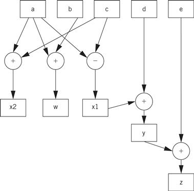
Figure 5.6 An extended data flow graph for our sample basic block.
The data flow graph is generally drawn in the form shown in Figure 5.7. Here, the variables are not explicitly represented by nodes. Instead, the edges are labeled with the variables they represent. As a result, a variable can be represented by more than one edge. However, the edges are directed and all the edges for a variable must come from a single source. We use this form for its simplicity and compactness.

Figure 5.7 Standard data flow graph for our sample basic block.
The data flow graph for the code makes the order in which the operations are performed in the C code much less obvious. This is one of the advantages of the data flow graph. We can use it to determine feasible reorderings of the operations, which may help us to reduce pipeline or cache conflicts. We can also use it when the exact order of operations simply doesn’t matter. The data flow graph defines a partial ordering of the operations in the basic block. We must ensure that a value is computed before it is used, but generally there are several possible orderings of evaluating expressions that satisfy this requirement.
5.3.2 Control/Data Flow Graphs
A CDFG uses a data flow graph as an element, adding constructs to describe control. In a basic CDFG, we have two types of nodes: decision nodes and data flow nodes. A data flow node encapsulates a complete data flow graph to represent a basic block. We can use one type of decision node to describe all the types of control in a sequential program. (The jump/branch is, after all, the way we implement all those high-level control constructs.)
Figure 5.8 shows a bit of C code with control constructs and the CDFG constructed from it. The rectangular nodes in the graph represent the basic blocks. The basic blocks in the C code have been represented by function calls for simplicity. The diamond-shaped nodes represent the conditionals. The node’s condition is given by the label, and the edges are labeled with the possible outcomes of evaluating the condition.

Figure 5.8 C code and its CDFG.
Building a CDFG for a while loop is straightforward, as shown in Figure 5.9. The while loop consists of both a test and a loop body, each of which we know how to represent in a CDFG. We can represent for loops by remembering that, in C, a for loop is defined in terms of a while loop. This for loop
for (i = 0; i < N; i++) {
loop_body();
}
is equivalent to
i = 0;
while (i < N) {
loop_body();
i++;
}

Figure 5.9 A while loop and its CDFG.
Hierarchical representation
For a complete CDFG model, we can use a data flow graph to model each data flow node. Thus, the CDFG is a hierarchical representation—a data flow CDFG can be expanded to reveal a complete data flow graph.
An execution model for a CDFG is very much like the execution of the program it represents. The CDFG does not require explicit declaration of variables but we assume that the implementation has sufficient memory for all the variables. We can define a state variable that represents a program counter in a CPU. (When studying a drawing of a CDFG, a finger works well for keeping track of the program counter state.) As we execute the program, we either execute the data flow node or compute the decision in the decision node and follow the appropriate edge, depending on the type of node the program counter points on. Even though the data flow nodes may specify only a partial ordering on the data flow computations, the CDFG is a sequential representation of the program. There is only one program counter in our execution model of the CDFG, and operations are not executed in parallel.
The CDFG is not necessarily tied to high-level language control structures. We can also build a CDFG for an assembly language program. A jump instruction corresponds to a nonlocal edge in the CDFG. Some architectures, such as ARM and many VLIW processors, support predicated execution of instructions, which may be represented by special constructs in the CDFG.