
4.8 Design Example: Alarm Clock
Our first system design example will be an alarm clock. We use a microprocessor to read the clock’s buttons and update the time display. Because we now have an understanding of I/O, we work through the steps of the methodology to go from a concept to a completed and tested system.
4.8.1 Requirements
The basic functions of an alarm clock are well understood and easy to enumerate. Figure 4.32 illustrates the front panel design for the alarm clock. The time is shown as four digits in 12-hour format; we use a light to distinguish between AM and PM. We use several buttons to set the clock time and alarm time. When we press the hour and minute buttons, we advance the hour and minute, respectively, by one. When setting the time, we must hold down the set time button while we hit the hour and minute buttons; the set alarm button works in a similar fashion. We turn the alarm on and off with the alarm on and alarm off buttons. When the alarm is activated, the alarm ready light is on. A separate speaker provides the audible alarm.
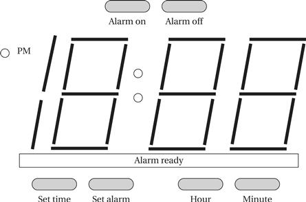
Figure 4.32 Front panel of the alarm clock.
We are now ready to create the requirements table:
| Name | Alarm clock |
| Purpose | A 24-hour digital clock with a single alarm. |
| Inputs | Six pushbuttons: set time, set alarm, hour, minute, alarm on, alarm off. |
| Outputs | Four-digit, clock-style output. PM indicator light. Alarm ready light. Buzzer. |
| Functions | Default mode: the display shows the current time. PM light is on from noon to midnight. Hour and minute buttons are used to advance time and alarm, respectively. Pressing one of these buttons increments the hour/minute once. Depress set time button: This button is held down while hour/minute buttons are pressed to set time. New time is automatically shown on display. Depress set alarm button: While this button is held down, display shifts to current alarm setting; depressing hour/minute buttons sets alarm value in a manner similar to setting time. Alarm on: puts clock in alarm-on state, causes clock to turn on buzzer when current time reaches alarm time, turns on alarm ready light. Alarm off: turns off buzzer, takes clock out of alarm-on state, turns off alarm ready light. |
| Performance | Displays hours and minutes but not seconds. Should be accurate within the accuracy of a typical microprocessor clock signal. (Excessive accuracy may unreasonably drive up the cost of generating an accurate clock.) |
| Manufacturing cost | Consumer product range. Cost will be dominated by the microprocessor system, not the buttons or display. |
| Power | Powered by AC through a standard power supply. |
| Physical size and weight | Small enough to fit on a nightstand with expected weight for an alarm clock. |
4.8.2 Specification
The basic function of the clock is simple, but we do need to create some classes and associated behaviors to clarify exactly how the user interface works.
Figure 4.33 shows the basic classes for the alarm clock. Borrowing a term from mechanical watches, we call the class that handles the basic clock operation the Mechanism class. We have three classes that represent physical elements: Lights* for all the digits and lights, Buttons* for all the buttons, and Speaker* for the sound output. The Buttons* class can easily be used directly by Mechanism. As discussed below, the physical display must be scanned to generate the digits output, so we introduce the Display class to abstract the physical lights.
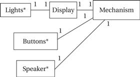
Figure 4.33 Class diagram for the alarm clock.
The details of the low-level user interface classes are shown in Figure 4.34. The Buzzer* class allows the buzzer to be turned on or off; we will use analog electronics to generate the buzz tone for the speaker. The Buttons* class provides read-only access to the current state of the buttons. The Lights* class allows us to drive the lights. However, to save pins on the display, Lights* provides signals for only one digit, along with a set of signals to indicate which digit is currently being addressed. We generate the display by scanning the digits periodically. That function is performed by the Display class, which makes the display appear as an unscanned, continuous display to the rest of the system.

Figure 4.34 Details of user interface classes for the alarm clock.
The Mechanism class is described in Figure 4.35. This class keeps track of the current time, the current alarm time, whether the alarm has been turned on, and whether it is currently buzzing. The clock shows the time only to the minute, but it keeps internal time to the second. The time is kept as discrete digits rather than a single integer to simplify transferring the time to the display. The class provides two behaviors, both of which run continuously. First, scan-keyboard is responsible for looking at the inputs and updating the alarm and other functions as requested by the user. Second, update-time keeps the current time accurate.

Figure 4.35 The Mechanism class.
Figure 4.36 shows the state diagram for update-time. This behavior is straightforward, but it must do several things. It is activated once per second and must update the seconds clock. If it has counted 60 seconds, it must then update the displayed time; when it does so, it must roll over between digits and keep track of AM-to-PM and PM-to-AM transitions. It sends the updated time to the display object. It also compares the time with the alarm setting and sets the alarm buzzing under the proper conditions.

Figure 4.36 State diagram for update-time.
The state diagram for scan-keyboard is shown in Figure 4.37. This function is called periodically, frequently enough so that all the user’s button presses are caught by the system. Because the keyboard will be scanned several times per second, we don’t want to register the same button press several times. If, for example, we advanced the minutes count on every keyboard scan when the set-time and minutes buttons were pressed, the time would be advanced much too fast. To make the buttons respond more reasonably, the function computes button activations—it compares the current state of the button to the button’s value on the last scan, and it considers the button activated only when it is on for this scan but was off for the last scan. Once computing the activation values for all the buttons, it looks at the activation combinations and takes the appropriate actions. Before exiting, it saves the current button values for computing activations the next time this behavior is executed.


Figure 4.37 State diagram for scan-keyboard.
Figure 4.38 Preprocessing button inputs.
4.8.3 System Architecture
The software and hardware architectures of a system are always hard to completely separate, but let’s first consider the software architecture and then its implications on the hardware.
The system has both periodic and aperiodic components—the current time must obviously be updated periodically, and the button commands occur occasionally.
It seems reasonable to have the following two major software components:
• An interrupt-driven routine can update the current time. The current time will be kept in a variable in memory. A timer can be used to interrupt periodically and update the time. As seen in the subsequent discussion of the hardware architecture, the display must be sent the new value when the minute value changes. This routine can also maintain the PM indicator.
• A foreground program can poll the buttons and execute their commands. Because buttons are changed at a relatively slow rate, it makes no sense to add the hardware required to connect the buttons to interrupts. Instead, the foreground program will read the button values and then use simple conditional tests to implement the commands, including setting the current time, setting the alarm, and turning off the alarm. Another routine called by the foreground program will turn the buzzer on and off based on the alarm time.
An important question for the interrupt-driven current time handler is how often the timer interrupts occur. A one-minute interval would be very convenient for the software, but a one-minute timer would require a large number of counter bits. It is more realistic to use a one-second timer and to use a program variable to count the seconds in a minute.
The foreground code will be implemented as a while loop:
while (TRUE) {
read_buttons(button_values); /* read inputs */
process_command(button_values); /* do commands */
check_alarm(); /* decide whether to turn on the alarm */
}
The loop first reads the buttons using read_buttons(). In addition to reading the current button values from the input device, this routine must preprocess the button values so that the user interface code will respond properly. The buttons will remain depressed for many sample periods because the sample rate is much faster than any person can push and release buttons. We want to make sure that the clock responds to this as a single depression of the button, not one depression per sample interval. As shown in Figure 4.38, this can be done by performing a simple edge detection on the button input—the button event value is 1 for one sample period when the button is depressed and then goes back to 0 and does not return to 1 until the button is depressed and then released. This can be accomplished by a simple two-state machine.
The process_command() function is responsible for responding to button events. The check_alarm() function checks the current time against the alarm time and decides when to turn on the buzzer. This routine is kept separate from the command processing code because the alarm must go on when the proper time is reached, independent of the button inputs.
We have determined from the software architecture that we will need a timer connected to the CPU. We will also need logic to connect the buttons to the CPU bus. In addition to performing edge detection on the button inputs, we must also of course debounce the buttons.
The final step before starting to write code and build hardware is to draw the state transition graph for the clock’s commands. That diagram will be used to guide the implementation of the software components.
4.8.4 Component Design and Testing
The two major software components, the interrupt handler and the foreground code, can be implemented relatively straightforwardly. Because most of the functionality of the interrupt handler is in the interruption process itself, that code is best tested on the microprocessor platform. The foreground code can be more easily tested on the PC or workstation used for code development. We can create a testbench for this code that generates button depressions to exercise the state machine. We will also need to simulate the advancement of the system clock. Trying to directly execute the interrupt handler to control the clock is probably a bad idea—not only would that require some type of emulation of interrupts, but it would require us to count interrupts second by second. A better testing strategy is to add testing code that updates the clock, perhaps once per four iterations of the foreground while loop.
The timer will probably be a stock component, so we would then focus on implementing logic to interface to the buttons, display, and buzzer. The buttons will require debouncing logic. The display will require a register to hold the current display value in order to drive the display elements.
4.8.5 System Integration and Testing
Because this system has a small number of components, system integration is relatively easy. The software must be checked to ensure that debugging code has been turned off. Three types of tests can be performed. First, the clock’s accuracy can be checked against a reference clock. Second, the commands can be exercised from the buttons. Finally, the buzzer’s functionality should be verified.