
1.4 Design Example: Model Train Controller
In order to learn how to use UML to model systems, we will specify a simple system, a model train controller, which is illustrated in Figure 1.14. The user sends messages to the train with a control box attached to the tracks. The control box may have familiar controls such as a throttle, emergency stop button, and so on. Because the train receives its electrical power from the two rails of the track, the control box can send signals to the train over the tracks by modulating the power supply voltage. As shown in the figure, the control panel sends packets over the tracks to the receiver on the train. The train includes analog electronics to sense the bits being transmitted and a control system to set the train motor’s speed and direction based on those commands. Each packet includes an address so that the console can control several trains on the same track; the packet also includes an error correction code (ECC) to guard against transmission errors. This is a one-way communication system—the model train cannot send commands back to the user.

Figure 1.14 A model train control system.
We start by analyzing the requirements for the train control system. We will base our system on a real standard developed for model trains. We then develop two specifications: a simple, high-level specification and then a more detailed specification.
1.4.1 Requirements
Before we can create a system specification, we have to understand the requirements. Here is a basic set of requirements for the system:
• The console shall be able to control up to eight trains on a single track.
• The speed of each train shall be controllable by a throttle to at least 63 different levels in each direction (forward and reverse).
• There shall be an inertia control that shall allow the user to adjust the responsiveness of the train to commanded changes in speed. Higher inertia means that the train responds more slowly to a change in the throttle, simulating the inertia of a large train. The inertia control will provide at least eight different levels.
• There shall be an emergency stop button.
• An error detection scheme will be used to transmit messages.
We can put the requirements into our chart format:
| Name | Model train controller |
| Purpose | Control speed of up to eight model trains |
| Inputs | Throttle, inertia setting, emergency stop, train number |
| Outputs | Train control signals |
| Functions | Set engine speed based upon inertia settings; respond to emergency stop |
| Performance | Can update train speed at least 10 times per second |
| Manufacturing cost | $50 |
| Power | 10 W (plugs into wall) |
| Physical size and weight | Console should be comfortable for two hands, approximate size of standard keyboard; weight less than 2 pounds |
We will develop our system using a widely used standard for model train control. We could develop our own train control system from scratch, but basing our system upon a standard has several advantages in this case: It reduces the amount of work we have to do and it allows us to use a wide variety of existing trains and other pieces of equipment.
1.4.2 DCC
The Digital Command Control (DCC) standard (http://www.nmra.org/standards/DCC/standards_rps/DCCStds.html) was created by the National Model Railroad Association to support interoperable digitally controlled model trains. Hobbyists started building homebrew digital control systems in the 1970’s and Marklin developed its own digital control system in the 1980s. DCC was created to provide a standard that could be built by any manufacturer so that hobbyists could mix and match components from multiple vendors.
DCC documents
The DCC standard is given in two documents:
• Standard S-9.1, the DCC Electrical Standard, defines how bits are encoded on the rails for transmission.
• Standard S-9.2, the DCC Communication Standard, defines the packets that carry information.
Any DCC-conforming device must meet these specifications. DCC also provides several recommended practices. These are not strictly required but they provide some hints to manufacturers and users as to how to best use DCC.
The DCC standard does not specify many aspects of a DCC train system. It doesn’t define the control panel, the type of microprocessor used, the programming language to be used, or many other aspects of a real model train system. The standard concentrates on those aspects of system design that are necessary for interoperability. Overstandardization, or specifying elements that don’t really need to be standardized, only makes the standard less attractive and harder to implement.
DCC Electrical Standard
The Electrical Standard deals with voltages and currents on the track. Although the electrical engineering aspects of this part of the specification are beyond the scope of the book, we will briefly discuss the data encoding here. The standard must be carefully designed because the main function of the track is to carry power to the locomotives. The signal encoding system should not interfere with power transmission either to DCC or non-DCC locomotives. A key requirement is that the data signal should not change the DC value of the rails.
The data signal swings between two voltages around the power supply voltage. As shown in Figure 1.15, bits are encoded in the time between transitions, not by voltage levels. A 0 is at least 100 μs while a 1 is nominally 58 μs. The durations of the high (above nominal voltage) and low (below nominal voltage) parts of a bit are equal to keep the DC value constant. The specification also gives the allowable variations in bit times that a conforming DCC receiver must be able to tolerate.

Figure 1.15 Bit encoding in DCC.
The standard also describes other electrical properties of the system, such as allowable transition times for signals.
DCC Communication Standard
The DCC Communication Standard describes how bits are combined into packets and the meaning of some important packets. Some packet types are left undefined in the standard but typical uses are given in Recommended Practices documents.
We can write the basic packet format as a regular expression:
![]() (Eq. 1.1)
(Eq. 1.1)
In this regular expression:
• P is the preamble, which is a sequence of at least 10 1 bits. The command station should send at least 14 of these 1 bits, some of which may be corrupted during transmission.
• S is the packet start bit. It is a 0 bit.
• A is an address data byte that gives the address of the unit, with the most significant bit of the address transmitted first. An address is eight bits long. The addresses 00000000, 11111110, and 11111111 are reserved.
• s is the data byte start bit, which, like the packet start bit, is a 0.
• D is the data byte, which includes eight bits. A data byte may contain an address, instruction, data, or error correction information.
A packet includes one or more data byte start bit/data byte combinations. Note that the address data byte is a specific type of data byte.
Baseline packet
A baseline packet is the minimum packet that must be accepted by all DCC implementations. More complex packets are given in a Recommended Practice document. A baseline packet has three data bytes: An address data byte gives the intended receiver of the packet; the instruction data byte provides a basic instruction; and an error correction data byte is used to detect and correct transmission errors.
The instruction data byte carries several pieces of information. Bits 0-3 provide a 4-bit speed value. Bit 4 has an additional speed bit, which is interpreted as the least significant speed bit. Bit 5 gives direction, with 1 for forward and 0 for reverse. Bits 7-8 are set at 01 to indicate that this instruction provides speed and direction.
The error correction data byte is the bitwise exclusive OR of the address and instruction data bytes.
Packet transmission rates
The standard says that the command unit should send packets frequently because a packet may be corrupted. Packets should be separated by at least 5 ms.
1.4.3 Conceptual Specification
DCC specifies some important aspects of the system, particularly those that allow equipment to interoperate. But DCC deliberately does not specify everything about a model train control system. We need to round out our specification with details that complement the DCC spec. A conceptual specification allows us to understand the system a little better. We will use the experience gained by writing the conceptual specification to help us write a detailed specification to be given to a system architect. This specification doesn’t correspond to what any commercial DCC controllers do, but it is simple enough to allow us to cover some basic concepts in system design.
Commands
A train control system turns commands into packets. A command comes from the command unit while a packet is transmitted over the rails. Commands and packets may not be generated in a 1-to-1 ratio. In fact, the DCC standard says that command units should resend packets in case a packet is dropped during transmission. Figure 1.16 shows a generic command class and several specific commands derived from that base class. Estop (emergency stop) requires no parameters whereas Set-speed and Set-inertia do.

Figure 1.16 Class diagram for the train controller commands.
We now need to model the train control system itself. There are clearly two major subsystems: the command unit and the train-board component. Each of these subsystems has its own internal structure. The basic relationship between them is illustrated in Figure 1.17. This figure shows a UML collaboration diagram; we could have used another type of figure, such as a class or object diagram, but we wanted to emphasize the transmit/receive relationship between these major subsystems. The command unit and receiver are each represented by objects; the command unit sends a sequence of packets to the train’s receiver, as illustrated by the arrow. The notation on the arrow provides both the type of message sent and its sequence in a flow of messages; because the console sends all the messages, we have numbered the arrow’s messages as 1..n. Those messages are of course carried over the track. Because the track isn’t a computer component and is purely passive, it does not appear in the diagram. However, it would be perfectly legitimate to model the track in the collaboration diagram, and in some situations it may be wise to model such nontraditional components in the specification diagrams. For example, if we are worried about what happens when the track breaks, modeling the tracks would help us identify failure modes and possible recovery mechanisms.
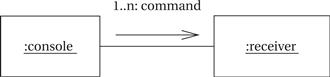
Figure 1.17 UML collaboration diagram for major subsystems of the train controller system.
Let’s break down the command unit and receiver into their major components. The console needs to perform three functions: read the state of the front panel on the command unit, format messages, and transmit messages. The train receiver must also perform three major functions: receive the message, interpret the message (taking into account the current speed, inertia setting, etc.), and actually control the motor. In this case, let’s use a class diagram to represent the design; we could also use an object diagram if we wished. The UML class diagram is shown in Figure 1.18. It shows the console class using three classes, one for each of its major components. These classes must define some behaviors, but for the moment we will concentrate on the basic characteristics of these classes:
• The Console class describes the command unit’s front panel, which contains the analog knobs and hardware to interface to the digital parts of the system.
• The Formatter class includes behaviors that know how to read the panel knobs and creates a bit stream for the required message.
• The Transmitter class interfaces to analog electronics to send the message along the track.
There will be one instance of the Console class and one instance of each of the component classes, as shown by the numeric values at each end of the relationship links. We’ve also shown some special classes that represent analog components, ending the name of each with an asterisk:
• Knobs* describes the actual analog knobs, buttons, and levers on the control panel.
• Sender* describes the analog electronics that send bits along the track.
Likewise, the Train makes use of three other classes that define its components:
• The Receiver class knows how to turn the analog signals on the track into digital form.
• The Controller class includes behaviors that interpret the commands and figures out how to control the motor.
• The Motor interface class defines how to generate the analog signals required to control the motor.
We define two classes to represent analog components:
• Detector* detects analog signals on the track and converts them into digital form.
• Pulser* turns digital commands into the analog signals required to control the motor speed.
We have also defined a special class, Train set, to help us remember that the system can handle multiple trains. The values on the relationship edge show that one train set can have t trains. We would not actually implement the train set class, but it does serve as useful documentation of the existence of multiple receivers.
1.4.4 Detailed Specification
Now that we have a conceptual specification that defines the basic classes, let’s refine it to create a more detailed specification. We won’t make a complete specification, but we will add detail to the classes and look at some of the major decisions in the specification process to get a better handle on how to write good specifications.
At this point, we need to define the analog components in a little more detail because their characteristics will strongly influence the Formatter and Controller. Figure 1.19 shows a class diagram for these classes; this diagram shows a little more detail than Figure 1.18 because it includes attributes and behaviors of these classes. The Panel has three knobs: train number (which train is currently being controlled), speed (which can be positive or negative), and inertia. It also has one button for emergency-stop. When we change the train number setting, we also want to reset the other controls to the proper values for that train so that the previous train’s control settings are not used to change the current train’s settings. To do this, Knobs* must provide a set-knobs behavior that allows the rest of the system to modify the knob settings. (If we wanted or needed to model the user, we would expand on this class definition to provide methods that a user object would call to specify these parameters.) The motor system takes its motor commands in two parts. The Sender and Detector classes are relatively simple: They simply put out and pick up a bit, respectively.
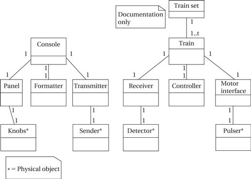
Figure 1.18 A UML class diagram for the train controller showing the composition of the subsystems.
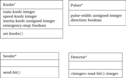
Figure 1.19 Classes describing analog physical objects in the train control system.
To understand the Pulser class, let’s consider how we actually control the train motor’s speed. As shown in Figure 1.20, the speed of electric motors is commonly controlled using pulse-width modulation: Power is applied in a pulse for a fraction of some fixed interval, with the fraction of the time that power is applied determining the speed. The digital interface to the motor system specifies that pulse width as an integer, with the maximum value being maximum engine speed. A separate binary value controls direction. Note that the motor control takes an unsigned speed with a separate direction, while the panel specifies speed as a signed integer, with negative speeds corresponding to reverse.

Figure 1.20 Controlling motor speed by pulse-width modulation.
Figure 1.21 shows the classes for the panel and motor interfaces. These classes form the software interfaces to their respective physical devices. The Panel class defines a behavior for each of the controls on the panel; we have chosen not to define an internal variable for each control because their values can be read directly from the physical device, but a given implementation may choose to use internal variables. The new-settings behavior uses the set-knobs behavior of the Knobs* class to change the knobs settings whenever the train number setting is changed. The Motor-interface defines an attribute for speed that can be set by other classes. As we will see in a moment, the controller’s job is to incrementally adjust the motor’s speed to provide smooth acceleration and deceleration.

Figure 1.21 Class diagram for the panel and motor interface.
The Transmitter and Receiver classes are shown in Figure 1.22. They provide the software interface to the physical devices that send and receive bits along the track. The Transmitter provides a distinct behavior for each type of message that can be sent; it internally takes care of formatting the message. The Receiver class provides a read-cmd behavior to read a message off the tracks. We can assume for now that the receiver object allows this behavior to run continuously to monitor the tracks and intercept the next command. (We consider how to model such continuously running behavior as processes in Chapter 6.) We use an internal variable to hold the current command. Another variable holds a flag showing when the command has been processed. Separate behaviors let us read out the parameters for each type of command; these messages also reset the new flag to show that the command has been processed. We don’t need a separate behavior for an Estop message because it has no parameters—knowing the type of message is sufficient.

Figure 1.22 Class diagram for the Transmitter and Receiver.
Now that we have specified the subsystems around the formatter and controller, it is easier to see what sorts of interfaces these two subsystems may need.
The Formatter class is shown in Figure 1.23. The formatter holds the current control settings for all of the trains. The send-command method is a utility function that serves as the interface to the transmitter. The operate function performs the basic actions for the object. At this point, we only need a simple specification, which states that the formatter repeatedly reads the panel, determines whether any settings have changed, and sends out the appropriate messages. The panel-active behavior returns true whenever the panel’s values do not correspond to the current values.
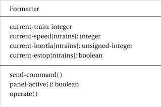
Figure 1.23 Class diagram for the Formatter class.
The role of the formatter during the panel’s operation is illustrated by the sequence diagram of Figure 1.24. The figure shows two changes to the knob settings: first to the throttle, inertia, or emergency stop; then to the train number. The panel is called periodically by the formatter to determine if any control settings have changed. If a setting has changed for the current train, the formatter decides to send a command, issuing a send-command behavior to cause the transmitter to send the bits. Because transmission is serial, it takes a noticeable amount of time for the transmitter to finish a command; in the meantime, the formatter continues to check the panel’s control settings. If the train number has changed, the formatter must cause the knob settings to be reset to the proper values for the new train.

Figure 1.24 Sequence diagram for transmitting a control input.
We have not yet specified the operation of any of the behaviors. We define what a behavior does by writing a state diagram. The state diagram for a very simple version of the operate behavior of the Formatter class is shown in Figure 1.25. This behavior watches the panel for activity: If the train number changes, it updates the panel display; otherwise, it causes the required message to be sent. Figure 1.26 shows a state diagram for the panel-active behavior.

Figure 1.25 State diagram for the formatter operate behavior.

Figure 1.26 State diagram for the panel-activate behavior.
The definition of the train’s Controller class is shown in Figure 1.27. The operate behavior is called by the receiver when it gets a new command; operate looks at the contents of the message and uses the issue-command behavior to change the speed, direction, and inertia settings as necessary. A specification for operate is shown in Figure 1.28.

Figure 1.27 Class diagram for the Controller class.

Figure 1.28 State diagram for the Controller operate behavior.
The operation of the Controller class during the reception of a set-speed command is illustrated in Figure 1.29. The Controller’s operate behavior must execute several behaviors to determine the nature of the message. Once the speed command has been parsed, it must send a sequence of commands to the motor to smoothly change the train’s speed.
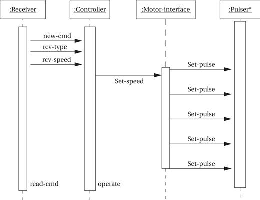
Figure 1.29 Sequence diagram for a set-speed command received by the train.
Refining command classes
It is also a good idea to refine our notion of a command. These changes result from the need to build a potentially upward-compatible system. If the messages were entirely internal, we would have more freedom in specifying messages that we could use during architectural design. But because these messages must work with a variety of trains and we may want to add more commands in a later version of the system, we need to specify the basic features of messages for compatibility. There are three important issues. First, we need to specify the number of bits used to determine the message type. We choose three bits because that gives us five unused message codes. Second, we need to include information about the length of the data fields, which is determined by the resolution for speeds and inertia set by the requirements. Third, we need to specify the error correction mechanism; we choose to use a single-parity bit. We can update the classes to provide this extra information as shown in Figure 1.30.

Figure 1.30 Refined class diagram for the train controller commands.
1.4.5 Lessons Learned
We’ve learned a few things in this exercise beyond gaining experience with UML notation. First, standards are important. We often can’t avoid working with standards but standards often save us work and allow us to make use of components designed by others. Second, specifying a system isn’t easy. You often learn a lot about the system you are trying to build by writing a specification. Third, specification invariably requires making some choices that may influence the implementation. Good system designers use their experience and intuition to guide them when these kinds of choices must be made.