
7.4 Specifications
In this section we take a look at some advanced techniques for specification and how they can be used.
7.4.1 Control-Oriented Specification Languages
SDL
We have already seen how to use state machines to specify control in UML. An example of a widely used state machine specification language is the SDL language[Roc82], which was developed by the communications industry for specifying communication protocols, telephone systems, and so forth. As illustrated in Figure 7.6, SDL specifications include states, actions, and both conditional and unconditional transitions between states. SDL is an event-oriented state machine model because transitions between states are caused by internal and external events.
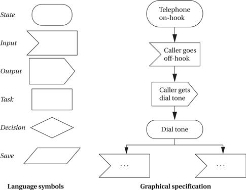
Figure 7.6 The SDL specification language.
Statecharts
Other techniques can be used to eliminate clutter and clarify the important structure of a state-based specification. The Statechart[Har87] is one well-known technique for state-based specification that introduced some important concepts. The Statechart notation uses an event-driven model. Statecharts allow states to be grouped together to show common functionality. There are two basic groupings: OR and AND. Figure 7.7 shows an example of an OR state by comparing a traditional state transition diagram with a Statechart described via an OR state. The state machine specifies that the machine goes to state s4 from any of s1, s2, or s3 when they receive the input i2. The Statechart denotes this commonality by drawing an OR state around s1, s2, and s3 (the name of the OR state is given in the small box at the top of the state). A single transition out of the OR state s123 specifies that the machine goes into state s4 when it receives the i2 input while in any state included in s123. The OR state still allows interesting transitions between its member states. There can be multiple ways to get into s123 (via s1 or s2), and there can be transitions between states within the OR state (such as from s1 to s3 or s2 to s3). The OR state is simply a tool for specifying some of the transitions relating to these states.

Figure 7.7 An OR state in Statecharts.
Figure 7.8 shows an example of an AND state specified in Statechart notation as compared to the equivalent in the traditional state machine model. In the traditional model, there are numerous transitions between the states; there is also one entry point into this cluster of states and one exit transition out of the cluster.

Figure 7.8 An AND state in Statecharts.
In the Statechart, the AND state sab is decomposed into two components, sa and sb. When the machine enters the AND state, it simultaneously inhabits the state s1 of component sa and the state s3 of component sb. We can think of the system’s state as multidimensional. When it enters sab, knowing the complete state of the machine requires examining both sa and sb.
The names of the states in the traditional state machine reveal their relationship to the AND state components. Thus, state s1-3 corresponds to the Statechart machine having its sa component in s1 and its sb component in s3, and so forth. We can exit this cluster of states to go to state s5 only when, in the traditional specification, we are in state s2-4 and receive input r. In the AND state, this corresponds to sa in state s2, sb in state s4, and the machine receiving the r input while in this composite state. Although the traditional and Statechart models describe the same behavior, each component has only two states, and the relationships between these states are much simpler to see.
AND/OR tables
Leveson et al. [Lev94] used a different format, the AND/OR table, to describe similar relationships between states. An example AND/OR table and the Boolean expression it describes are shown in Figure 7.9. The rows in the AND/OR table are labeled with the basic variables in the expression. Each column corresponds to an AND term in the expression. For example, the AND term (cond2 and not cond3) is represented in the second column with a T for cond2, an F for cond3, and a dash (don’t-care) for cond1; this corresponds to the fact that cond2 must be T and cond3 F for the AND term to be true. We use the table to evaluate whether a given condition holds in the system. The current states of the variables are compared to the table elements. A column evaluates to true if all the current variable values correspond to the requirements given in the column. If any one of the columns evaluates to true, then the table’s expression evaluates to true, as we would expect for an AND/OR expression. The most important difference between this notation and Statecharts is that don’t-cares are explicitly represented in the table, which was found to be of great help in identifying problems in a specification table.

Figure 7.9 An AND/OR table.
7.4.2 Advanced Specifications
This section is devoted to a single example of a sophisticated system. Example 7.3 describes the specification of a real-world, safety-critical system used in aircraft. The specification techniques developed to ensure the correctness and safety of this system can also be used in many applications, particularly in systems where much of the complexity goes into the control structure.
Example 7.3 The TCAS II Specification
TCAS II (Traffic Alert and Collision Avoidance System) is a collision avoidance system for aircraft. Based on a variety of information, a TCAS unit in an aircraft keeps track of the position of other nearby aircraft. If TCAS decides that a mid-air collision may be likely, it uses audio commands to suggest evasive action—for example, a prerecorded voice may warn “DESCEND! DESCEND!” if TCAS believes that an aircraft above poses a threat and that there is room to maneuver below. TCAS makes sophisticated decisions in real time and is clearly safety critical. On the one hand, it must detect as many potential collision events as possible (within the limits of its sensors, etc.). On the other hand, it must generate as few false alarms as possible, because the extreme maneuvers it recommends are themselves potentially dangerous.
Leveson et al. [Lev94] developed a specification for the TCAS II system. We won’t cover the entire specification here, but just enough to provide its flavor. The TCAS II specification was written in their RSML language. They use a modified version of Statechart notation for specifying states, in which the inputs to and outputs of the state are made explicit. The basic state notation looks like this:

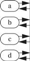
They also use a transition bus to show sets of states in which there are transitions between all (or almost all) states. In this example, there are transitions from a, b, c, or d to any of the other states:
The top-level description of the collision avoidance system (CAS) is relatively simple:

This diagram specifies that the system has Power-off and Power-on states. In the power-on state, the system may be in Standby or Fully operational mode. In the Fully operational mode, three components are operating in parallel, as specified by the AND state: the own-aircraft subsystem, a subsystem to keep track of up to 30 other aircraft, and a subsystem to keep track of up to 15 Mode S ground stations, which provide radar information.
The next diagram shows a specification of the Own-Aircraft AND state. Once again, the behavior of Own-Aircraft is an AND composition of several subbehaviors. The Effective-SL and Alt-SL states are two ways to control the sensitivity level (SL) of the system, with each state representing a different sensitivity level. Differing sensitivities are required depending on distance from the ground and other factors. The Alt-Layer state divides the vertical airspace into layers, with this state keeping track of the current layer. Climb-Inhibit and Descent-Inhibit states are used to selectively inhibit climbs (which may be difficult at high altitudes) or descents (clearly dangerous near the ground), respectively. Similarly, the Increase-Climb-Inhibit and Increase-Descend-Inhibit states can inhibit high-rate climbs and descents. Because the Advisory-Status state is rather complicated, its details are not shown here.
