
A wide range of security technologies exists that provides solutions for securing network access and data transport mechanisms within the corporate network infrastructure. Many of the technologies overlap in solving problems that relate to ensuring user or device identity, data integrity, and data confidentiality.
NOTE
Throughout this book, authentication, authorization, and access control are incorporated into the concept of identity. Although these concepts are distinct, they all pertain to each individual user of the network—be it a person or device. Each person or device is a distinct entity that has separate abilities within the network and is allowed access to resources based on who they are. Although in the purest sense, identity really pertains only to authentication, in many cases, it makes sense to discuss the entities' authorization and access control at the same time.
Authentication refers to the process of validating the claimed identity of an end user or a device (such as clients, servers, switches, routers, firewalls, and so on). Authorization refers to the process of granting access rights to a user, groups of users, or specified system; access control refers to limiting the flow of information from the resources of a system to only the authorized persons or systems in the network. In most of the cases studied here, authorization and access control are subsequent to successful authentication.
This chapter describes security technologies commonly used to establish identity (authentication, authorization, and access control) and to ensure some degree of data integrity and confidentiality in a network. Data integrity ensures that any alteration or destruction of data by people who are not explicitly intended to modify it is detected; data confidentiality ensures that only the entities allowed to see the data see it in a usable format.
The intent is to develop a basic understanding of how these technologies can be implemented in corporate networks and to identify their strengths and weaknesses. The following categories have been selected in an attempt to group the protocols according to shared attributes:
Identity technologies
Application layer security protocols
Transport layer security protocols
Network layer security
Link layer security protocols
Public key infrastructure and distribution models
NOTE
Many of the technologies discussed here either have been or are in the process of being standardized by the IETF. For information on more technical details and the latest developments, refer to Appendix A, “Sources of Technical Information.” Appendix A contains pointers to the IETF working groups that produce the RFCs and drafts relating to the technologies discussed here.
This section describes the primary technologies used to establish identity for a host, an end-user, or both. Authentication is an extremely critical element because everything is based on who you are. In many corporate networks, you would not grant authorized access to specific parts of the network before establishing who is trying to gain access to restricted resources. Who needs to identify who is a consideration. In some instances, the initiator of a communication is the required entity to authenticate, in others it is the responder. Sometimes mutual authentication is required. To complicate things even further, there is the additional consideration of whether to authenticate only the end device or also the actual user and possibly to associate them together. In many instances, multiple end users use the same device and may need different privileges across the network. Also, the proliferation of laptops make it easier for people to travel and get connected back to corporate offices anywhere on the globe. If a laptop gets stolen and if an automated authentication scheme is used to authenticate and allow access privileges based only on the device identity, however, large security implications apply.
How foolproof the authentication method is depends on the technology used and how foolproof the procedures are.
Authentication methods can loosely be categorized as those where there is local control and those where you provide authentication verification through a trusted third party.
One of the potential weaknesses in some authentication methods is who you trust. Many authentication methods rely on a third party to verify someone's identity. The strength of this verification is the limiting factor in the strength of the authentication. When using a third party to authenticate an end user or device, ask yourself, “What is the likelihood that the third party I'm counting on to provide the authentication verification has been compromised?”
The technologies discussed in this section include variants of secure passwords, which provide varying degrees of security and are offered by most vendors today. Many protocols authorize some form of connection setup after authentication has been successfully verified. In dialup environments, a peer-to-peer, link-level connection is established; sometimes, additional access control mechanisms can be used at higher levels of the protocol stack, such as permitting access to hosts with certain IP addresses accessing specific applications. This discussion covers different protocols that often use an initial authentication process to then grant authorization and access control.
NOTE
You can use digital certificates as an authentication method, as discussed in detail in the “Public Key Infrastructure and Distribution Models” section later in this chapter.
Although passwords are often used as proof for authenticating a user or device, passwords can easily be compromised if they are easy to guess, if they are not changed often enough, and if they are transmitted in cleartext across a network. To make passwords more secure, more robust methods are offered by encrypting the password or by modifying the encryption so that the encrypted value changes each time. This is the case with most one-time password schemes; the most common being the S/Key protocol and the token password authentication schemes.
The S/Key One-Time Password System, released by Bellcore and defined in RFC 1760, is a one-time, password-generation scheme based on MD4 and MD5. The S/Key protocol is designed to counter a replay attack when a user is attempting to log in to a system. A replay attack in the context of login is when someone eavesdrops on a network connection to get the login ID and password of a legitimate user and later uses it to gain access to the network.
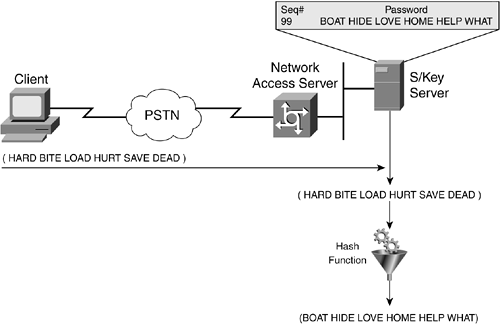
The operation of the S/Key protocol is client/server-based; the client is typically a PC, and the server is some flavor of UNIX. Initially, both the client and the server must be configured with the same pass phrase and an iteration count. The iteration count specifies how many times a given input will be applied to the hash function. The client initiates the S/Key exchange by sending an initialization packet; the server responds with a sequence number and seed, as shown in Figure 2-1.

The client then computes the one-time password, a process that involves three distinct steps: a preparatory step, a generation step, and an output function. (See Figure 2-2.)
In the preparatory step, the client enters a secret pass phrase. This pass phrase is concatenated with the seed that was transmitted from the server in cleartext.
The generation step applies the secure hash function multiple times, producing a 64-bit final output.
The output function takes the 64-bit one-time password and displays it in readable form.

The last phase is for the client to pass the one-time password to the server, where it can be verified. (See Figure 2-3.)
The server has a file (on the UNIX reference implementation, it is /etc/skeykeys) containing, for each user, the one-time password from the last successful login. To verify an authentication attempt, the authentication server passes the received one-time password through the secure hash function once. If the result of this operation matches the stored previous one-time password, the authentication is successful and the accepted one-time password is stored for future use.
Because the number of hash function applications executed by the client decreases by one each time, this ensures a unique sequence of generated passwords. However, at some point, the user must re-initialize the system to avoid being unable to log in again. The system is re-initialized using the keyinit command, which allows the changing of the secret pass phrase, the iteration count, and the seed.
When computing the S/Key password on the client side, the client pass phrase can be of any length—more than eight characters is recommended. The use of the nonsecret seed allows a client to use the same secret pass phrase on multiple machines (using different seeds) and to safely recycle secret pass phrases by changing the seed.
NOTE
Many implementations require the generated one-time password to be entered either using a cut-and-paste approach, or manually. In manual entry scenarios, the one-time password is converted to, and accepted, as a sequence of six short (one- to four-letter) English words. Each word is chosen from a dictionary of 2048 words; at 11 bits per word, all one-time passwords may be encoded. Interoperability requires that all S/Key system hosts and calculators use the same dictionary.
S/Key is an alternative to simple passwords. Free as well as commercial implementations are widely available.
Token authentication systems generally require the use of a special card (called a token card), although some implementations are done using software to alleviate the problem of losing the token card. These types of authentication mechanisms are based on one of two alternative schemes: challenge-response and time-synchronous authentication.
The challenge-response approach is shown in Figure 2-4. The following steps carry out the authentication exchange:
The user dials in to an authentication server, which then issues a prompt for a user ID.
The user provides the ID to the server, which then issues a challenge—a random number that appears on the user's screen.
The user enters that challenge number into the token card, a credit card type of device, which then encrypts the challenge with the user's encryption key and displays a response.
The user types this response and sends it to the authentication server. While the user is obtaining a response from the token, the authentication server calculates what the appropriate response should be based on its database of user keys.
When the server receives the user's response, it compares that response with the one it has calculated.
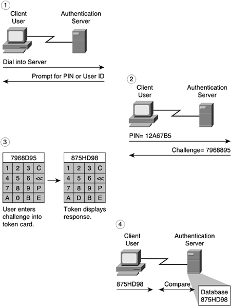
If the two responses match, the user is granted access to the network. If they don't match, access is denied.
Figure 2-5 shows the time-synchronous authentication scheme. In this scheme, a proprietary algorithm executes in the token and on the server to generate identical numbers that change over time. The user dials in to the authentication server, which issues a prompt for an access code. The user enters a personal identification number (PIN) on the token card, resulting in digits displayed at that moment on the token. These digits represent the one-time password and are sent to the server. The server compares this entry with the sequence it generated; if they match, it grants the user access to the network.

A popular variant is to require a password prompt in addition to the PIN to increase the amount of information required to compromise the identity. In some cases, the time-synchronous token systems can be set up without the user being required to enter a PIN on the token card to obtain the present access code. The motivation in these cases is that administrators have found that employees would etch or write the PIN onto the token card directly; however, should the card be misplaced or stolen, the card would be easily abused. This latter scenario, where the user is not required to enter any information on the token card, is strongly discouraged.
Use of either the challenge-response or time-synchronous token password authentication scheme generally requires the user to carry a credit card type of device to provide authentication credentials. This can be a burden to some users because they have to remember to carry the device, but it has the flexibility to allow fairly secure authenticated access from anywhere in the world. It is extremely useful for mobile users who frequently log in from remote sites. If the mobile users have their own laptop, the token can be installed as software, which relieves the burden of remembering to carry an additional device. These schemes are very robust and scalable from a centralized database point of view.
NOTE
Using the one-time password scheme only protects you from replay attacks when initially logging in to the site. If you then continue to log in to other machines at the campus site, the password will be sent in the clear. It is best to combine one-time password use with some form of confidentiality (encryption) technique if protection is required for more than just the initial login sequence.
Passwords are incorporated into many protocols that provide authentication services. For dial-in connections, the Point-to-Point Protocol (PPP) is most often used to establish a dial-in connection over serial lines or ISDN. PPP authentication mechanisms include the Password Authentication Protocol (PAP), the Challenge Handshake Protocol (CHAP), and the Extensible Authentication Protocol (EAP). In some of these cases, the peer device is being authenticated rather than the user of the device.
NOTE
In the section “Link Layer Security Technologies” later in this chapter, other protocols such as L2TP and PPPoE are discussed; these other protocols rely on the PPP authentication mechanisms. These technologies extend the point-to-point link across non-point-to-point networks and because the PPP frames may be forwarded beyond the local loop of a dialup connection, additional considerations need to be taken into account for the path over which those frames traverse.
PPP Link Layer
The PPP protocol data unit (PDU) uses the High-Level Data Link Control (HDLC) frame as stipulated in ISO 3309-1979 (and amended by ISO 3309-1984/PDAD1).
Figure 2-6 shows the PPP frame format.

The fields of a PPP frame are as follows:
Flag—. A single byte that indicates the beginning or end of a frame. The Flag field consists of the binary sequence 01111110.
Address—. A single byte that contains the binary sequence 11111111, the standard broadcast address. PPP does not assign individual station addresses.
Control—. A single byte that contains the binary sequence 00000011, which calls for transmission of user data in an unsequenced frame.
Protocol—. Two bytes that identify the protocol encapsulated in the Information field of the frame. The most current values of the Protocol field are specified in the most recent Assigned Numbers Request for Comments (RFCs).
Data—. Zero or more bytes that contain the datagram for the protocol specified in the Protocol field. The end of the Information field is found by locating the closing flag sequence and allowing two bytes for the FCS field. The default maximum length of the Information field is 1500 bytes. By prior agreement, consenting PPP implementations can use other values for the maximum Information field length.
Frame Check Sequence (FCS)—. Normally two bytes. By prior agreement, consenting PPP implementations can use a four-byte FCS for improved error detection.
The LCP can negotiate modifications to the standard PPP frame structure. However, modified frames will always be clearly distinguishable from standard frames.
The Password Authentication Protocol (PAP) provides a simple way for a peer to establish its identity to the authenticator using a two-way handshake. This is done only at initial link establishment. There exist three PAP frame types, as shown in Figure 2-7.

After the link establishment phase is completed, the authenticate-request packet is used to initiate the PAP authentication. This packet contains the peer name and password, as shown in Figure 2-8.

This request packet is sent repeatedly until a valid reply packet is received or an optional retry counter expires. If the authenticator receives a Peer-ID/Password pair that is both recognizable and acceptable, it should reply with an Authenticate-Ack (where Ack is short for acknowledge). If the Peer-ID/Password pair is not recognizable or acceptable, the authenticator should reply with an Authenticate-Nak (where Nak is short for negative acknowledge).
Figure 2-9 shows the sequence of PPP negotiations between a branch router (the peer) trying to authenticate to the network access server (NAS, the authenticator).

PAP is not a strong authentication method. PAP authenticates only the peer, and passwords are sent over the circuit “in the clear.” PAP authentication is only performed once during a session. There is no protection from replay attacks or repeated trial-and-error attacks. The peer is in control of the frequency and timing of the attempts.
The Challenge Handshake Authentication Protocol (CHAP), defined in RFC 1994, is used to periodically verify the identity of a host or end user using a three-way handshake. CHAP is performed at initial link establishment and can be repeated any time after the link has been established. Four CHAP frame types exist, as shown in Figure 2-10.

Figure 2-11 shows a scenario in which a branch router (the peer) is trying to authenticate to the NAS (the authenticator).

CHAP imposes network security by requiring that the peers share a plaintext secret. This secret is never sent over the link. The following sequence of steps is carried out:
After the link establishment phase is complete, the authenticator sends a challenge message to the peer. The challenge consists of an identifier (ID), a random number (the challenge value), and either the host name of the local device or the name of the user on the remote device.
The receiving peer calculates a response value using a one-way hash function; the input to the one-way hash function is the ID, the secret, and the challenge value, concatenated in that order.
The peer sends the challenge response, which consists of the following:
The ID
A response value (the calculated hash value from Step 2)
Either the host name of the remote device, or the name of the user on the remote device
When the authenticator receives the challenge response, it verifies the secret by looking up the name given in the response and performing the same encryption operation. The authenticator checks the response against its own calculation of the expected hash value.
If the values match, the authenticator acknowledges the authentication and sends a success message, and the LCP establishes the link.
The secret passwords must be identical on the remote and local devices. These secrets should be agreed on, generated, and exchanged out of band in a secure manner. Because the secret is never transmitted, other devices are prevented from stealing it and gaining illegal access to the system. Without the proper response, the remote device cannot connect to the local device.
CHAP provides protection against playback attack through the use of an incrementally changing identifier and a variable challenge value. The use of repeated challenges is intended to limit the time of exposure to any single attack. The authenticator is in control of the frequency and timing of the challenges.
Either CHAP peer can act as the authenticator; there is no requirement in the specification that authentication must be full duplex or that the same protocol must be used in both directions.
NOTE
Typically, MD5 is used as the CHAP one-way hash function; the shared secrets are required to be stored in plaintext form. Despite the claim in RFC 1994 to the contrary, however, irreversably encrypted passwords can be used as long as the password is correctly preprocessed (that is, encrypted) by the peer before being processed by the CHAP algorithm. Microsoft has a variation of CHAP (MS-CHAP and MS-CHAPv2), in which the password is stored encrypted in both the peer and the authenticator. Therefore, MS-CHAP can take advantage of irreversibly encrypted password databases commonly available, whereas the standards-based CHAP cannot.
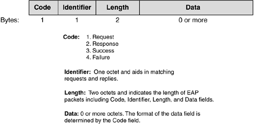
The PPP Extensible Authentication Protocol (EAP) is defined in RFC 2284, although there is a newer draft version numbered RFC 2284bis. EAP is a general protocol for PPP authentication that supports multiple authentication mechanisms. It provides its own support for duplicate elimination and retransmission. Fragmentation is not supported within EAP itself; however, individual EAP methods may support this.
EAP does not select a specific authentication mechanism at the link control phase; rather, it postpones this until the authentication phase so that the authenticator can request more information before determining the specific authentication mechanism. This arrangement also permits the use of a “back-end” server, which actually implements the various authentication mechanisms, whereas the PPP authenticator merely passes through the authentication exchange. This has the added benefit of not requiring the authenticator to be updated to support each new authentication method.
Figure 2-12 shows the EAP packet format.
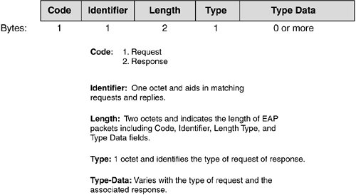
Additional code types are specified in the data portion of the EAP request/response packets, as shown in Figure 2-13.

New code types are continually being defined to allow for various authentication mechanisms. The following are some commonly used ones:
Identity type (1)—. Used to query the identity of the peer. Generally, the authenticator issues this as the initial request. An optional displayable message could be included to prompt the peer in the case where there is the expectation of interaction with a user. A response message is typically sent of the same type containing the requested information.
Notification type (2)—. Optionally used to display a message from the authenticator to the peer. For example, it could be a notification that a password is about to expire.
Nak type (response only) (3)—. Valid only in a response message. It is sent in reply to a request where the desired authentication type is unacceptable.
MD5-Challenge type (4)—. Analogous to the PPP CHAP protocol(with MD5 as the specified algorithm). The request contains a “challenge” message to the peer. The response sent in reply to the request is either of type 4 (MD5-Challenge) or type 3 (Nak). Note that the use of the Identifier field in the MD5-Challenge type differs from that described in RFC 1994. EAP allows for retransmission of MD5-Challenge request packets, whereas RFC 1994 states that both the Identifier and Challenge fields must change each time a Challenge (the CHAP equivalent of the MD5-Challenge request packet) is sent.
One-Time Password (OTP) type (5)—. The OTP system is defined in “A One-Time Password System” (RFC 2289) and “OTP Extended Responses” (RFC 2243). The request contains a displayable message containing an OTP challenge. The response sent in reply to the request will be of type 5 (OTP) or type 3 (Nak).
Generic Token Card (GTC) type (6)—. Defined for use with various token card implementations that require user input. The request contains a displayable message, and the response contains the token card information necessary for authentication. Typically, this is information read by a user from the token card device and entered as ASCII text. The response sent in reply to the request will be of type 6 (GTC) or type 3 (Nak).
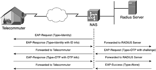
Figure 2-14 shows how PPP EAP works between two network infrastructure devices.
In Figure 2-14, the branch router (the peer) is trying to authenticate to the NAS (the authenticator). The sequence of steps is as follows:
When the link establishment phase is complete, the authenticator sends one or more requests to authenticate the peer. The request has a Type field to indicate what is being requested.
NOTE
Typically, the authenticator sends an initial identity request followed by one or more requests for authentication information. However, an initial identity request is not required and may be bypassed in cases where the identity is presumed (for example, with leased lines, dedicated dialups, and so on).
The peer sends a response packet in reply to each request. As with the request packet, the response packet contains a Type field that corresponds to the Type field of the request.
The authenticator ends the authentication phase with a success or failure packet.
Figure 2-15 shows an example where a RADIUS server is used as a back-end server to actually implement the authentication mechanism. In this case, the client is a telecommuter dialing in to a NAS to access the corporate network. The NAS (PPP authenticator) merely passes through the authentication exchange.
EAP adds more flexibility to PPP authentication and provides the capability to use new technologies—such as digital certificates—when they become widely available. The EAP protocol can support multiple authentication mechanisms without having to prenegotiate a particular one. Devices (for instance, a NAS, switch, or access point) do not have to understand each authentication method and can act as a passthrough agent for a backend authentication server. Although the support for passthrough is optional in the specification, many vendors are implementing it. An authenticator can authenticate local users while at the same time acting as a passthrough for nonlocal users and authentication methods it does not implement locally.
PPP authentication is required for dial-in connectivity. Any of the three standard mechanisms—PAP, CHAP, and EAP—can be used. Most current implementations are taking advantage of the flexibility of EAP, and it is widely available. Table 2-1 gives a summary of the strengths and weaknesses of these mechanisms.
Table 2-1. PPP Authentication Summary
Many protocols require authentication verification before providing authorization and access rights to the user or device. The previous sections of this chapter discussed a variety of authentication methods. This section details the protocols that make use of these authentication mechanisms. TACACS+, RADIUS, Kerberos, DCE, and FORTEZZA are examples of such protocols. TACACS+ and RADIUS are often used in dial-in environments to provide a scalable authentication database and can incorporate a variety of authentication methods. Kerberos is a protocol used in some campus environments to first verify that users and the network services they use are really who and what they claim to be before granting access privileges. For completeness, the Distributed Computing Environment (DCE) and FORTEZZA authentication mechanisms are included in this section, although their use is not widespread.
802.1x is an IEEE specification that enables authentication and key management for IEEE 802 local-area networks. IEEE 802.1x is not a single authentication method; rather it uses the Extensible Authentication Protocol (EAP) as its authentication framework. This technology is also included because its application is widely deployable in many networking scenarios.
The TACACS+ protocol is the latest generation of TACACS. TACACS is a simple UDP-based access control protocol originally developed by BBN for the MILNET. Cisco has enhanced (extended) TACACS several times, and Cisco's implementation, based on the original TACACS, is referred to as XTACACS. The fundamental differences between TACACS, XTACACS, and TACACS+ are given here:
TACACS+ uses TCP for its transport. The server daemon usually listens at port 49, the login port assigned for the TACACS protocol. This port is reserved in the assigned number's RFC for both UDP and TCP. Current TACACS and extended TACACS implementations also use port 49.
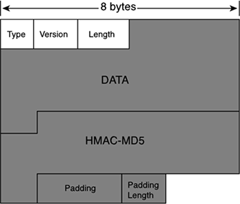
TACACS+ is a client/server protocol; the TACACS+ client is typically a NAS, and the TACACS+ server is usually a daemon process running on a UNIX or Windows NT machine. A fundamental design component of TACACS+ is the separation of authentication, authorization, and accounting. Figure 2-16 shows the TACACS+ header format.

TACACS+ allows for arbitrary length and content authentication exchanges, which allows any authentication mechanism to be used with TACACS+ clients (including PPP PAP, PPP CHAP, PPP EAP, token cards, and Kerberos). Authentication is not mandatory; it is a site-configured option. Some sites do not require it at all; others require it only for certain services.
TACACS+ authentication has three packet types:
START, which is always sent by the client
CONTINUE, which is always sent by the client
REPLY, which is always sent by the server
Authentication begins when the NAS (TACACS+ client) receives a connection request that needs to be authenticated. The client then sends a START message to the server. The START message describes the type of authentication to be performed (for example, simple cleartext password, PAP, or CHAP), and may contain the username and some authentication data. The START packet is sent only as the first message in a TACACS+ authentication session, or as the packet immediately following a restart. (A restart may be requested by the server in a REPLY packet.) A START packet always has a sequence number equal to 1.
In response to a START packet, the server sends a REPLY, which includes the authentication result. The REPLY message indicates whether the authentication is finished, or whether it should continue. If the REPLY indicates that authentication should continue, the message also indicates what new information is requested. The client gets that information and returns it in a CONTINUE message. This process repeats until all authentication information is gathered, and the authentication process concludes. The server responds to the last CONTINUE message with a REPLY.
The authentication result contained in a TACACS+ server REPLY can be one of the following three messages:
ACCEPT—. The user is authenticated and if authorization is configured on the NAS, the authorization process can start.
REJECT—. The user failed to authenticate, in which case the user might be denied further access or is prompted to retry the login sequence.
ERROR—. Indicates that an error occurred sometime during the authentication process; in which case, the NAS may try to use an alternative method to authenticate the user.
Authorization is the action of determining what a user is allowed to do. Generally, authentication precedes authorization, but, this is not required. An authorization request may indicate that the user is not authenticated. (That is, we don't know who they are.) In this case, it is up to the authorization agent to determine whether an unauthenticated user is allowed the services in question.
When authentication is completed (if authentication is used), the client can start the authorization process, if authorization is required. An authorization session is defined as a single pair of messages: a request followed by a response. The authorization Request message contains a fixed set of fields that describe the authenticity of the user or process, and a variable set of arguments that describes the services and options for which authorization is requested.
NOTE
In TACACS+, authorization does not merely provide yes or no answers—it may also customize the service for the particular user. Here are some examples of when authorization would be performed: when a user first logs in and wants to start a shell, and when a user starts PPP and wants to use IP over PPP with a particular IP address. The TACACS+ server daemon might respond to these requests by allowing the service, by placing a time restriction on the login shell, or by requiring IP access lists on the PPP connection.
Accounting is typically the third action after authentication and authorization. Accounting is the action of recording what a user is doing or has done. Accounting in TACACS+ can serve two purposes:
It may be used to account for services used, such as in a billing environment.
It may be used as an auditing tool for security services.
To this end, TACACS+ supports three types of accounting records:
Start records indicate that a service is about to begin.
Stop records indicate that a service has just terminated.
Update records are intermediate notices that indicate that a service is still being performed.
TACACS+ accounting records contain all the information used in the authorization records and also contain accounting-specific information such as start and stop times (when appropriate) and resource usage information.
Transactions between the TACACS+ client and TACACS+ server are authenticated through the use of a shared secret, which is never sent over the network. Typically, the secret is manually configured in both entities. TACACS+ encrypts all traffic between the TACACS+ client and the TACACS+ server daemon. The encryption is done through the use of MD5 and the XOR functionality. (See the following sidebar on XOR.) The following steps are used to create the ciphertext:
A hash (message digest) is calculated by using a concatenation of the session ID, shared secret key, version number, and sequence number as input to the MD5 algorithm. From this first hash, a second one is calculated by concatenating the first hash, session ID, version number, and sequence number as input to the MD5 algorithm. This process is repeated an implementation specific number of times.
All the calculated hashes are concatenated and then truncated to the length of the data that is to be encrypted, which results in what is termed the pseudo_pad.
A bytewise XOR is done on the pseudo_pad with the data that is to be encrypted, and this produces the resulting ciphertext.
The recipient of the ciphertext can calculate the pseudo_pad on its own because it is already preconfigured with a shared secret. An XOR of this pseudo_pad with the ciphertext results in the cleartext data.
Figure 2-17 shows the interaction between a dial-in user and the TACACS+ client and server.

The Remote Address Dial-In User Service (RADIUS) protocol was developed by Livingston Enterprises, Inc., as an access server authentication and accounting protocol. In June 1996, the RADIUS protocol specification was submitted to the IETF. The RADIUS specification (RFC 2865) is a proposed standard, and the RADIUS accounting specification (RFC 2866) is an informational RFC.
RADIUS uses UDP as its transport. Although some early implementations of RADIUS used port 1645, the official UDP port to use is 1812. Generally, the RADIUS protocol is considered to be a connectionless service. Issues related to server availability, retransmission, and timeouts are handled by the RADIUS-enabled devices rather than by the transmission protocol.
RADIUS is a client/server protocol. The RADIUS client is typically a NAS; the RADIUS server is usually a daemon process running on a UNIX or Windows NT machine. The client is responsible for passing user information to designated RADIUS servers and then acting on the response that is returned. RADIUS servers are responsible for receiving user connection requests, authenticating the user, and then returning all configuration information necessary for the client to deliver the service to the user. A RADIUS server can act as a proxy client to other RADIUS servers or to other kinds of authentication servers. Figure 2-18 shows the RADIUS packet format.

The RADIUS server can support a variety of methods to authenticate a user. When the server is provided with the username and original password given by the user, the server can support PPP PAP or CHAP, UNIX login, and other authentication mechanisms. What is supported depends on what a vendor has implemented.
Typically, a user login consists of a query (access-request) from the NAS to the RADIUS server and a corresponding response (access-accept or access-reject) from the server. The access-request packet contains the username, encrypted password, NAS IP address, and port. The format of the request also provides information about the type of session the user wants to initiate.
When the RADIUS server receives the access-request packet from the NAS, it searches a database for the username listed. If the username does not exist in the database, either a default profile is loaded or the RADIUS server immediately sends an access-reject message. This access-reject message can be accompanied by an optional text message, which may indicate the reason for the refusal.
In RADIUS, the authentication and authorization functionalities are coupled together. If the username is found and the password is correct, the RADIUS server returns an access-accept response, including a list of attribute-value pairs that describe the parameters to be used for this session. Typical parameters include service type (shell or framed), protocol type, IP address to assign the user (static or dynamic), access list to apply, or a static route to install in the NAS routing table. The configuration information in the RADIUS server defines what will be installed on the NAS.
The accounting features of the RADIUS protocol can be used independently of RADIUS authentication or authorization. The RADIUS accounting functions allow data to be sent at the start and end of sessions, indicating the amount of resources (such as time, packets, bytes, and so on) used during the session. An Internet service provider (ISP) might use RADIUS access control and accounting software to meet special security and billing needs.
Transactions between the RADIUS client and RADIUS server are authenticated through the use of a shared secret, which is never sent over the network. However, communication between the client and server is in the clear except for the user passwords, which are encrypted. The following steps are used to encrypt the user-supplied password:
The 16-byte random number from the Request Authenticator field and the preconfigured shared secret are input to an MD5 hash function, which results in a 16-byte hash.
The user-provided password is padded at the end with nulls until it is 16 bytes in length.
The hash from Step 1 is XOR'd with the padded password to create the encrypted password.
The recipient of the encrypted password calculates its own hash because it also has knowledge of the preconfigured shared secret. When this hash is XOR'd with the encrypted password, the result is the password in cleartext.
Figure 2-19 shows the RADIUS login and authentication process.

NOTE
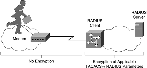
With both TACACS+ and RADIUS, it is important to remember that encryption is performed between the TACACS+/RADIUS client and the TACACS+/RADIUS server. If the TACACS+/RADIUS client is a NAS and not the client PC, any communication between the PC and the NAS is not encrypted. (See Figure 2-20.) In addition, the communication between the NAS and the TACACS+/RADIUS server may traverse networks, which can easily be tapped into and snooped. Therefore, any authentication mechanism using cleartext passwords, such as PPP PAP, should not be used.
Kerberos is a secret-key network authentication protocol, developed at Massachusetts Institute of Technology (MIT), that uses the Data Encryption Standard (DES) cryptographic algorithm for encryption and authentication. The Kerberos version 5 protocol is an Internet standard specified by RFC 1510.
Kerberos was designed to authenticate user requests for network resources. Kerberos is based on the concept of a trusted third party that performs secure verification of users and services. In the Kerberos protocol, this trusted third party is called the key distribution center (KDC), sometimes also called the authentication server. The primary use of Kerberos is to verify that users and the network services they use are really who and what they claim to be. To accomplish this, a trusted Kerberos server issues “tickets” to users. These tickets have a limited life span and are stored in the user's credential cache. They can later be used in place of the standard username-and-password authentication mechanism.
A number of Kerberos-related terms are defined here. The following definitions will make the subsequent text easier to understand:
Credential—. A general term that refers to authentication tickets, such as ticket-granting tickets (TGTs) and service credentials. Kerberos credentials verify the identity of a user or service. If a network service decides to trust the Kerberos server that issued a ticket, it can be used in place of retyping in a username and password. Credentials have the default life span of 8 hours.
Instance—. An authorization-level label for Kerberos principals.
Kerberized—. Applications and services that have been modified to support the Kerberos credential infrastructure.
Kerberos realm—. A domain consisting of users, hosts, and network services that are registered to a Kerberos server. The Kerberos server is trusted to verify a user's or network service's identity to another user or network service. Kerberos realms must always be in uppercase characters. TCP fragmentation must also be defined on the KDC server. The Kerberos realm is also used to map a DNS domain to a Kerberos realm.
Kerberos sever—. A daemon running on a network host. Users and network services register their identities with the Kerberos server. Network services query the Kerberos server to authenticate to other network services.
Key distribution center (KDC)—. A Kerberos server and database program running on a network host.
Principal—. Also known as a Kerberos identity, this is who you are or what a service is according to a Kerberos server.
Service credential—. A credential for a network service. When issued from the KDC, this credential is encrypted with the password shared by the network service and the KDC, and with the user's TGT.
SRVTAB—. A password that a network service shares with the KDC. The network service authenticates an encrypted service credential using the SRVTAB (also known s KEYTAB) to decrypt it.
Ticket-granting ticket (TGT)—. A credential that the KDC issues to authenticate users. When users receive a TGT, they can authenticate to network services within the Kerberos realm represented by the KDC.
Initially, the Kerberos client has knowledge of an encryption key known only to the user and the KDC, Kclient. Similarly, each application server shares an encryption key with the KDC, Kserver. (See Figure 2-21.)

When the client wants to create an association with a particular application server, the client uses the authentication request and response to first obtain a ticket and a session key from the KDC. (See Figure 2-22.)

The steps are as follows:
The client sends an authentication request to the KDC. This request contains the following information:
Its claimed identity
The name of the application server
A requested expiration time for the ticket
A random number that will be used to match the authentication response with the request
The KDC verifies that the claimed identity exists in the Kerberos database and creates an authentication response. If pre-authentication is used, the client access rights are also verified.
The KDC returns the response to the client. The authentication response contains the following information:
The session key, Ksession
The assigned expiration time
The random number from the request
The name of the application server
Other information from the ticket
This information is all encrypted with the user's password, which was registered with the authentication server, Kclient. The KDC also returns a Kerberos ticket containing the random session key, Ksession, which will be used for authentication of the client to the application server; the name of the client to whom the session key was issued; and an expiration time after which the session key is no longer valid. The Kerberos ticket is encrypted using Kserver.
When the client receives the authentication reply, it prompts the user for the password. This password, Kclient, is used to decrypt the session key, Ksession.
Now the client is ready to communicate with the application server.
NOTE
Kclient is used as the bootstrap mechanism, but in subsequent communication between the KDC and the client, a short-term client key, Kclient-session, is used. Kclient-session is created by having the KDC convert the user's password to the short-term client key. The KDC sends the short-term client key, Kclient-session, encrypted with the user's password, to the client. The user decrypts the short-term client key and subsequent KDC to client communication use Kclient-session.
The application request and response is the exchange in which a client proves to an application server that it knows the session key embedded in a Kerberos ticket. Figure 2-23 shows the exchange.

The steps in the application request and response are as follows:
The client sends two things to the application server as part of the application request:
The Kerberos ticket (described earlier)
An authenticator, which includes the following (among other fields):
The current time
A checksum
An optional encryption key
These elements are all encrypted with the session key, Ksession, from the accompanying ticket.
After receiving the application request, the application server decrypts the ticket with Kserver, extracts the session key, Ksession, and uses the session key to decrypt the authenticator.
If the same key was used to encrypt the authenticator as was used to decrypt it, the checksum will match, and the verifier can assume that the authenticator was generated by the client named in the ticket and to whom the session key was issued. By itself, this check is not sufficient for authentication because an attacker can intercept an authenticator and replay it later to impersonate the user. For this reason, the verifier also checks the time stamp. If the time stamp is within a specified window (typically 5 minutes), centered around the current time on the verifier, and if the time stamp has not been seen on other requests within that window, the verifier accepts the request as authentic.
At this point, the identity of the client has been verified by the server. For some applications, the client also wants to be sure of the server's identity. If such mutual authentication is required, a third step is required.
The application server generates an application response by extracting the client's time from the authenticator and returns it to the client together with other information, all encrypted using the session key, Ksession.
The basic Kerberos authentication protocol allows a client with knowledge of the user's password to obtain a ticket and session key and to prove its identity to any verifier (usually an application server) registered with the KDC. The user's password must be presented each time the user performs authentication with a new verifier. A system should support single sign-on, where the user logs in to the system once and provides the password at that time; subsequent authentication occurs automatically.
The obvious way to cache the user's password on the workstation is dangerous. Although a Kerberos ticket and the key associated with it are valid for only a short time, an intruder knowing the user's password can obtain valid tickets and impersonate the user until the password is changed. This is why the short-term client key, Kclient-session, is used in place of the user's actual password in all but the initial bootstrap communication. The Kerberos approach is to cache only tickets and encryption keys (collectively called credentials) that will work for a limited time period.
The ticket-granting exchange of the Kerberos protocol allows a user to obtain tickets and encryption keys using such short-lived credentials, without re-entering the user's password. When the user first logs in, an authentication request is issued, and a ticket and the client session key for the ticket-granting service is returned by the KDC. This ticket, called a ticket-granting ticket (TGT), has a relatively short life (typically on the order of 8 hours). The response is decrypted, the ticket and session key are saved, and the user's password is forgotten. Subsequently, when the user wants to prove its identity to a new verifier, a new ticket is requested from the KDC using the ticket-granting exchange.
NOTE
The ticket-granting exchange is identical to the authentication exchange except that the ticket-granting request has embedded within it an application request (authenticating the client to the authentication server), and the ticket-granting response is encrypted using the client session key from the ticket-granting ticket rather than from the user's password.
Multiple realms, or domains, are supported in Kerberos to allow for scalable implementations. Assume that a corporation has implemented a Kerberos system with two separate realms, Italy and Hungary. When a client in Italy's realm connects to a server in Hungary's realm, Italy's KDC authenticates the client to Hungary's KDC. Hungary's KDC authenticates the client to Hungary's server. Multi-KDC chaining is not allowed, and trust for KDC chaining should go back only one level.
Several utility programs must be installed on the workstation to allow users to obtain Kerberos credentials (kinit), destroy credentials (kdestroy), list credentials (klist), and change their Kerberos passwords (kpasswd). Some sites choose to integrate the Kerberos login tool, kinit, with the workstation login program so that users do not have to type their password twice. This makes the use of Kerberos nearly transparent; users may not even be aware they are using Kerberos.
NOTE
Client/server applications must be modified to use Kerberos for authentication; such Kerberos-aware applications are said to be Kerberized.
You should also consider using a method of accurate time in all systems because Kerberos has a time-dependency issue through the use of time stamps. A synchronized, dependable mechanism of obtaining time is needed; most likely, the use of NTP is warranted.
The Distributed Computing Environment (DCE) is a set of functional specifications from the Open Software Foundation (OSF), found at http://www.opengroup.org/. DCE is a set of distributed computing technologies that provides security services to protect and control access to data; name services that make it easy to find distributed resources; and a highly scalable model for organizing widely scattered users, services, and data.
DCE has a modular design and supports authentication and authorization. The implemented authentication part is Kerberos version 5 (although, in theory, another mechanism can be substituted). The authorization part works in a manner similar to Kerberos but is implemented by privilege servers and registration servers. In practice, these are usually delivered with the KDC. The registration server ties the KDC with the user's privileges, which are found in the privilege server. The privilege server combines the universal unique ID (UUID) and the groups into a Kerberos ticket for secure transmission. Kerberos uses usernames (which may not always be consistent or unique across the enterprise). DCE uses the UUIDs, which are 128 bits long. On most systems, the user ID (UID) and group ID (GID) fields are 32 bits each.
In practice, a user can authenticate from any workstation with a username and password. The TGT is issued by the KDC. The workstation then uses that session key to form a session to the privilege server. The UUID and access control list (ACL) information is then passed to the workstation through a privilege ticket-granting ticket (PTGT) from the privilege server. The session key encrypted in the PTGT is used. The UUID and the group information are then used as the authorization information to allow or disallow access to services and resources.
NOTE
The DCE effort has not produced the groundswell effect its supporters hoped for. Today, some organizations have embraced it, but it is manpower-intensive to support (as is Kerberos) because it is fairly complex and relies on several other DCE services being implemented. Therefore, it is not found in use very often.
Multilevel Information Systems Security Initiative (MISSI) is a network security initiative, under the leadership of the National Security Agency (NSA). MISSI provides a framework for the development and evolution of interoperable, complementary security products to provide flexible, modular security for networked information systems across the Defense Information Infrastructure (DII) and the National Information Infrastructure (NII). These MISSI building blocks share a common network security infrastructure and are based on common security protocols and standards. Flexible solutions are tailored from these building blocks to meet a system's security requirements and may easily evolve, as future MISSI components provide additional backward-compatible security services and assurance.
Although some MISSI components result from government-contracted developments, most components are offered by commercial vendors as off-the-shelf products. The MISSI building blocks include the following:
FORTEZZA and FORTEZZA Plus
Firewalls
Guards
Inline encryptors
Trusted computing
FORTEZZA, combined with FORTEZZA-enabled applications, provides security services appropriate for protecting sensitive-but-unclassified (SBU) data. FORTEZZA provides the following features:
FORTEZZA Plus supports users of classified information with strong encryption methods. FORTEZZA Plus is an upgraded version of FORTEZZA that can be used to encrypt classified information up through Top Secret information. FORTEZZA Plus must be used in conjunction with a high assurance guard such as the secure network server (SNS), which ensures that the encryption of information is invoked. The use of FORTEZZA Plus to process classified information at different levels can be affected by the security limitations of other components in the system.
The FORTEZZA card is a cryptographic token in a PCMCIA form factor that provides encryption/ decryption and digital signature functions. It uses DSA and SHA for signature and message digests but NSA-designed key agreement and encryption algorithms. The key agreement algorithm is a variant of Diffie-Hellman called Key Exchange Algorithm (KEA) and the encryption algorithm is a block cipher called SKIPJACK. The card also stores certificates that include individualized key material used by the cryptographic and signature functions. The software on the workstation (PC, UNIX, and so on) exchanges commands and data with the FORTEZZA card to encrypt and sign messages before it sends them. It likewise uses the card to decrypt and verify the signatures of received messages. Each time the card is inserted into a workstation, the owner must unlock the card by entering a PIN. FORTEZZA card PINs can range from 4 to 12 characters. PINs may be a combination of alpha and numeric characters.
To perform application functions for the user, FORTEZZA must interoperate with FORTEZZA-enabled applications. These applications are either government developed or COTS applications (such as e-mail) that have been modified to interface with and use FORTEZZA security features. A large variety of such applications exist; more are being added as they are developed and tested.
Major types of FORTEZZA-enabled applications include these:
Electronic messaging—. FORTEZZA can secure e-mail, electronic data interchange (EDI), electronic commerce, and facsimile to provide message encryption, authentication, and data integrity.
World Wide Web (WWW)—. FORTEZZA can protect secure web transactions using strong identification and authentication and Secure Sockets Layer (SSL) interactions. Netscape has built a FORTEZZA-enabled version of its browser that links SSL with FORTEZZA.
File and media encryptors—. These encryptors are applications written to enable FORTEZZA to secure user files on storage media.
Identification and authentication—. After the FORTEZZA card has been installed in the workstation and the PIN has been correctly entered, the identity of the user is known and trusted. Access to other devices across a network can be authorized by exchanging this identification and authentication information in a trusted manner.
NOTE
FORTEZZA was originally designed by the NSA to provide strong cryptography while allowing the NSA to incorporate key escrow into the device. This was done using the Law Enforcement Access Field (LEAF), which contained the session key used to encrypt the transmitted traffic. The NSA could decrypt a communication by recovering the session key from the LEAF. The LEAF was embedded in the IV (initialization vector), which is a random block of data used to add randomness for key-generation material. However, due to the large key escrow controversy, in 1997 the NSA removed the LEAF. A dummy LEAF is now used for the IV for backward compatibility.
802.1x is the standard developed by the IEEE that enables authentication and key management for IEEE 802 local area networks. It allows for devices to be authenticated and authorized before they can logically connect to a port on a switch. In the case of Ethernet or Token Ring, these ports are physical entities that the device plugs into. In the case of wireless networks, however, these ports are logical entities known as associations.
The 802.1x standard defines three main logical entities (which may or may not reside on separate devices) as illustrated in Figure 2-24:
Supplicant—. A device that needs access to a LAN (for example, a laptop or workstation).
Authenticator—. A device that is responsible for initiating the authentication process and subsequently acts as a relay between the actual authentication server and the supplicant.
Authentication server—. A device that is responsible for performing the actual authentication and authorization on behalf of the authenticator. It contains profile information for all the users on the network and can use that information to authenticate and authorize users to connect to the ports on the authenticator.

The authentication data between the three entities is exchanged using EAP packets, which are carried in varying protocol packets. An encapsulation mechanism known as EAP over LANs (EAPOL) is defined in 802.1x to allow communication between the supplicant and the authenticator. EAPOL is defined separately for both Ethernet and Token Ring. The EAP messages are thus encapsulated using the EAPOL frames for transport between the supplicant and the authenticator. Upon receiving the EAPOL frame, the authenticator strips off the headers and, if the authenticator and authentication server reside on different devices, forwards the EAP message using another protocol. Communication between the authenticator and the authentication server is typically done via TACACS+ or RADIUS. RADIUS is generally preferred because it has EAP encapsulation extensions built into it. An example of the 802.1x transaction for authenticating a workstation to a LAN switch is shown in Figure 2-25. A RADIUS server is used as the authentication server.

This section focuses on technologies designed to address security needs for specific application protocols. The intent of this chapter is to familiarize the reader with most of the underlying security technologies available today, which form the basis for securing the network infrastructure. Some of the application layer security protocols are used as security solutions for specific environments, such as securing Voice over IP networks, as discussed in the next chapter.
The application layer pertains to the details of a particular application such as Telnet, FTP, or HTTP, and doesn't concern itself with the details of the movement of data across a network. This layer uses end-to-end protocols, in which end systems are responsible for providing security for the application protocol. Not many security protocols are specifically designed for individual applications. There are too many applications to make such an approach scalable. However, a few merit mentioning. Because the World Wide Web has become one of the fastest growing applications in the Internet, a specific security protocol was designed to be used for secure web transactions: Secure HyperText Transport Protocol (SHTTP). The Secure Multipurpose Internet Mail Extensions (S/MIME) protocol was designed to build security functionality on top of the MIME protocol to be easily integrated into e-mail and messaging products. Both are detailed here.
SHTTP is a secure message-oriented communications protocol designed to be used for securing messages using the HTTP protocol. The protocol preserves the characteristics of HTTP while allowing request and reply messages to be signed, authenticated, encrypted, or any combination of these (including no protection). SHTTP clients can communicate with non-HTTP-supported servers (although in these cases, the security features of SHTTP would not be applied).
Multiple key-management mechanisms are supported, including password-style manually shared secrets, and public key exchange. If some hosts do not have a public key pair, it is possible to use pre-arranged symmetric session keys to send confidential messages. These would usually be provided out of band.
Secure HTTP can verify message integrity and sender authenticity for a message using the computation of a message authentication code (MAC). The MAC is computed as a keyed hash over the document using a shared secret.
SHTTP uses option negotiation to allow clients and servers to agree on the following:
The main benefit of using an application-specific protocol such as SHTTP is that very specific security needs can be met. Consider these examples:
The application could deal with a message containing digital signatures by several different agents and make decisions based on who signed what.
Cryptographic security measures could be defined for individual web pages such that individually encrypted web pages could be published on any web server but could only be read by those with authorized keys.
In practice, SHTTP has achieved limited use. Transport layer security implementations are more easily available and more often used for web security.
S/MIME is short for Secure Multipurpose Internet Mail Extensions. The specification was designed to be easily integrated into e-mail and messaging products. S/MIME builds security on top of the industry-standard MIME protocol according to an equally important set of cryptographic standards, the Public Key Cryptography Standards (PKCS). Public key technologies are discussed later in this chapter. MIME was an enhancement to the original messaging specification defined in RFC 822, which restricted the message body to ASCII text. MIME added other forms of content by providing specifications for binary data.
S/MIME was originally developed by RSA Data Security, Inc., and was based on the PKCS #7 data format for the messages, and the X.509v3 format for certificates. PKCS#7 only supported RSA for key exchange, which meant that S/MIMEv2 only had support for RSA. The S/MIME working group was created in the IETF to add support for other key exchange and signature algorithms.
The S/MIMEv3 standard consists of five parts:
An additional protocol, Enhanced Security Services for S/MIME (RFC 2634), is a set of extensions to S/MIME to allow signed receipts, security labels, and secure mailing lists. The first two of these extensions work with either S/MIMEv2 or S/MIMEv3; secure mailing lists only work with S/MIMEv3.
NOTE
S/MIMEv2 is not an IETF standard. S/MIMEv2 requires the use of RSA key exchange, which is encumbered by U.S. patents held by RSA Data Security, Inc.; further, S/MIMEv2 requires the use of weak cryptography (40-bit keys). Both of these issues have prevented the protocol from being accepted as an IETF standard.
S/MIME provides a consistent way to send and receive secure MIME data by adding cryptographic signature and encryption services. It provides the following cryptographic security services for electronic messaging applications: authentication, message integrity and nonrepudiation of origin (using digital signatures), and privacy and data security (using encryption).
Separate requirements and recommendations are made for how receiving agents handle incoming messages and for how sending agents create outgoing messages. In general, they are based on the following strategy: Be liberal in what you receive and conservative in what you send. The separation for requirements on receiving agents and sending agents derives from the likelihood that there will be S/MIME systems that involve software other than traditional Internet mail clients. S/MIME is not restricted to mail; it can be used with any transport mechanism that transports MIME data, such as HTTP. Further, S/MIME can be used in automated message transfer agents that use cryptographic security services that do not require any human intervention, such as the signing of software-generated documents and the encryption of fax messages sent over the Internet.
The mandatory features required for S/MIME communication are as follows:
A sender may, of course, support other encryption algorithms. The sender is able to advertise the user's capabilities and preference for a choice of encryption algorithms.
The specification leaves it up to the implementers and users whether to either sign a message first or to provide confidentiality by encrypting the message first. When signing first, the signatories are then securely obscured by the encryption. When encrypting first, the signatories are exposed, but it is possible to verify signatures without removing the privacy protection. This may be useful in an environment were automatic signature verification is desired, because no private key material is required to verify a signature.
There are security ramifications to choosing whether to sign first or encrypt first. A recipient of a message that is encrypted and then signed can validate that the encrypted block was unaltered, but cannot determine any relationship between the signer and the unencrypted contents of the message. A recipient of a message that is signed and then encrypted can assume that the signed message itself has not been altered, but that a careful attacker may have changed the unauthenticated portions of the encrypted message.
Several characteristics of S/MIME make it a very flexible security solution for a variety of messaging applications:
Multiple signers—. Because CMS supports multiple signatures on a single message, S/MIME supports having a message signed by multiple senders.
Multiple recipients—. It is possible to send the same message securely to multiple recipients by encrypting the message with a single CEK and then encrypting the CEK individually for each recipient.
Receipt—. The ability to provide a receipt allows a sender to be sure that the recipient received a message and that it wasn't altered in transit. However, the recipient is not required to generate a receipt, and therefore lack of a receipt does not indicate that the recipient did not receive the message.
Forwarding—. Messages can be forwarded from one recipient to another while leaving the message signature intact and verifiable. This is possible because S/MIME uses a digital signature that signs the whole message.
Transport independence—. S/MIME provides end-to-end security at the application layer and is independent of any underlying transport. Therefore, in IP networks it can run over either TCP or UDP.
S/MIMEv3 is becoming widely deployed and is an underlying requirement for providing security services in Session Initiation Protocol (SIP)-based telephony networks, discussed in the next chapter.
The transport layer provides the details of moving the flow of data between two hosts. The following sections describe the security protocols that operate over TCP/IP or some other reliable but insecure transport. They are categorized as transport layer security protocols because their intent is to secure the transport layer and to provide methods for implementing privacy, authentication, and integrity above the transport layer. This layer uses end-to-end protocols, in which end systems are responsible for providing security for the transport protocol.
The Secure Socket Layer (SSL)/Transport Layer Security (TLS) protocol specifies a mechanism for providing data security layered between application protocols (such as HTTP, Telnet, NNTP, or FTP) and TCP/IP. It provides data encryption, server authentication, message integrity, and optional client authentication for a TCP/IP connection.
The original proprietary SSLv1 specification was designed by Netscape, and was subsequently modified into SSLv2 and publicly released in 1994. While SSLv2 was being deployed, Microsoft was coming up with its own incompatible variant, PCT. SSLv2 contained a number of security flaws, some of which PCT corrected, that ultimately led to the design of SSLv3. SSLv2 used RC4 for encryption and the MD5 algorithm for authentication. RSA keys were used for both authentication and key exchange; and at the time the SSLv2 specification came out, the U.S. government export laws limited the key length of a cryptographic algorithm to 40-bits, which many implementations supported. SSLv3 added support for DSS for authentication and DH for key agreement. The Transport Layer Security (TLS) working group was formed in 1996 to try and standardize an SSL-like protocol. TLS is based on SSLv3 and requires the use of DSS for authentication, DH for key agreement, and 3DES for encryption. In the following text, any reference to SSL is meant to imply SSLv3. Only the SSL operation is described because TLS is essentially the same.
NOTE
Although the TLS protocol operation is very similar to that of SSLv3, the key expansion and message authentication computations are incompatibe and therefore TLS and SSLv3 will not necessarily interoperate.
SSL assumes that the underlying packet delivery mechanism is reliable, and although in theory there are a number of transport protocols that could provide this service, SSL nearly always uses TCP as its transport.
The primary goal of SSL is to provide privacy and reliability between two communicating applications. SSL is a layered protocol consisting of the record protocol, which provides the envelope and security services for the four content layer protocols (handshake, alert, change cipher spec, and application). These are described as follows:
The record protocol—. This protocol is used to exchange application layer data. Application messages are fragmented into manageable blocks, optionally compressed, and a MAC (message authentication code) is applied. (SSL uses the term MAC, which is really a hash or message digest.) The result is encrypted and transmitted. The recipient takes the received data and decrypts it, verifies the MAC, decompresses and reassembles it, and delivers the result to the application protocol.
The handshake protocol—. This protocol negotiates the cryptographic parameters to be used between the client and the server session. When an SSL client and server first start communicating, they agree on a protocol version, select cryptographic algorithms, optionally authenticate each other, and use public key encryption techniques to generate shared secrets.
The alert protocol—. This protocol is used to indicate when errors have occurred or when a session between two hosts is being terminated. It is a one-way information-error message.
The change cipher spec protocol—. This protocol indicates a change in the encryption and authentication of records. It is a one-way messge and instigates a new handshake.
The application protocols—. These define any client/server protocols that use SSL and have specified ports defined. For example POP3S (995), NNTPS 563), HTTPS (443), LDAPS (636), and IRCS (994).
NOTE
Although the SSLv3 and TLS specifications allow for compression, the only compression currently stipulated is NULL. Therefore, compression is not commonly used.
Figure 2-26 shows a diagram of a SSL/TLS record. The content type specifies the content protocol used to process the plaintext fragment. A fragment is the portion of the data stream that is being transmitted. The protocol version is 3.0 for SSL and 3.1 for TLS. The record length is the length of the fragments, in bytes. These three fields comprise the header and are sent in the clear. The rest of the fragment is encrypted. It consists of the data that is sent, the computed MAC, and possibly some padding. The padding is required when using block ciphers such as DES because a block cipher requires the data to be encrypted to be a multiple of the block length.
The SSL handshake protocol provides connection security that has three basic properties:
The peer's identity can be authenticated using asymmetric, or public key, cryptography (for instance, RSA, DSS, and so on). This authentication can be made optional, but is generally required for at least one of the peers.
The negotiation of a shared secret is secure—the negotiated secret is unavailable to eavesdroppers, and for any authenticated connection the secret cannot be obtained, even by an attacker who can place himself in the middle of the connection.
The negotiation is reliable—no attacker can modify the negotiation communication without being detected by the parties to the communication.
Consider an example using a web client and server. The web client initiates an SSL session by connecting to an SSL-capable server. A typical SSL-capable web server accepts SSL connection requests on a different port (port 443 by default) than standard HTTP requests (port 80 by default). When the client connects to this port, it initiates a handshake that establishes the SSL session. After the handshake finishes, communication is encrypted using the negotiated shared session key and message integrity checks are performed until the SSL session expires. SSL creates a session during which the handshake must happen only once.
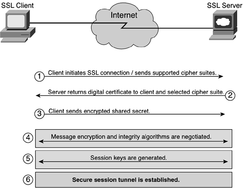
Figure 2-27 shows the SSL handshake process. (See the section “Public Key Infrastructure and Distribution Models” later in this chapter for more information about digital certificates.) The steps in the process are as follows:
The SSL client connects to the SSL server and requests the server to authenticate itself. It also includes the cipher suites it supports.
The server proves its identity by sending its digital certificate, which has its public key attached to it. This exchange may optionally include an entire certificate chain, up to some root certificate authority (CA).
Certificates are verified by checking validity dates and verifying that the certificate bears the signature of a trusted CA. The certificate is signed but not encrypted.
The server also returns a selected ciphersuite to use for the initial secure tunnel.
The client generates a random secret key, encrypts it with the server's public key, and sends it to the SSL server. Communication from now on is encrypted using the shared secret and specified cipher suite.
The message encryption algorithm and the hash function for integrity are negotiated for the session. Usually the client presents a list of all the algorithms it supports, and the server selects the strongest cipher available.
The client and server generate the session keys by following these steps:
The client generates a random number that it sends to the server, encrypted with the server's public key (obtained from the server's certificate).
The server responds with more random data (encrypted with the client's public key, if available; otherwise, it sends the data in cleartext).
The encryption keys are generated from this random data using hash functions.
The handshake process is complete and a secure session tunnel is created.
NOTE
Mutual authentication can be carried out by using the optional client-based authentication mechanism. This would occur after Step 3 in the preceding example. However, SSL only supports certificate-based client authentication, which is not often used due to the lack of a public key infrastructure. Instead, many application protocols incorporate their own client authentication mechanism, such as username/password or a one-time password technology such as S/Key. These authentication mechanisms are more secure when run over SSL.
The advantage of the SSL protocol is that it provides connection security that has three basic properties:
The connection is private. Encryption is used after an initial handshake to define a secret key. Symmetric cryptography is used for data encryption (for example, DES and RC4).
The peer's identity can be authenticated using asymmetric, or public key, cryptography (for example, RSA, and DSS).
The connection is reliable. Message transport includes a message integrity check using a keyed MAC. Secure hash functions (such as SHA and MD5) are used for MAC computations.
SSL/TLS is widely used with HTTP traffic. Other protocols are also starting to use SSL/TLS and have specific port numbers defined. Refer to http://www.iana.org/assignments/port-numbers for a list of officially assigned application port numbers. Table 2-2 lists some applications that are starting to use TLS to provide application-specific security. Note that most of these port numbers are specified for TCP and UDP.
The Secure Shell (SSH) is a protocol for secure remote login and other secure network services over an insecure network. It provides support for secure remote login, secure file transfer, and the secure forwarding of TCP/IP and X Window System traffic. It can automatically encrypt, authenticate, and compress transmitted data. The work in progress to define the SSH protocol ensures that the SSH protocol can provide strong security against cryptanalysis and protocol attacks, can work reasonably well without a global key management or certificate infrastructure, and can use existing certificate infrastructures (such as DNSSEC and X.509) when available.
The SSH protocol consists of three major components:
The transport layer protocol, which provides server authentication, confidentiality, and integrity with perfect forward secrecy. Optionally, it may also provide compression.
The user authentication protocol, which authenticates the client to the server.
The connection protocol, which multiplexes the encrypted tunnel into several logical channels.
The SSH transport layer is a secure low-level transport protocol. It provides strong encryption, cryptographic host authentication, and integrity protection. Authentication in SSH is host based; this protocol does not perform user authentication. A higher-level protocol for user authentication can be designed on top of SSH.
The protocol has been designed to be simple and flexible enough to allow parameter negotiation and to minimize the number of round trips. The key exchange method, the public key algorithm, the symmetric encryption algorithm, the message authentication algorithm, and the hash algorithm are all negotiated.
Data integrity is protected by including with each packet a MAC computed from a shared secret, a packet sequence number, and the contents of the packet.
SSH implementations can be found for UNIX, Windows, and Macintosh systems. It is a widely accepted protocol that uses well-known and well-established encryption, integrity, and public key algorithms.
Socket Security (SOCKS) is a transport layer-based secure networking proxy protocol. It is designed to provide a framework for client/server applications in both the TCP and UDP domains to conveniently and securely use the services of a network firewall.
SOCKS was originally developed by David and Michelle Koblas; the code was made freely available on the Internet. Several major revisions have occurred since then, but the software has remained freely available. SOCKS version 4 provides for unsecured firewall traversal for TCP-based client/server applications (including Telnet, FTP, and the popular information discovery protocols such as HTTP, WAIS, and Gopher). SOCKS version 5, defined in RFC 1928, extends the SOCKS version 4 model to include UDP, extends the framework to include provisions for generalized strong authentication schemes, and extends the addressing scheme to encompass domain name and IPv6 addresses.
A proposal currently exists to create a mechanism for managing the entrance or exit of IP multicast through a firewall. It does this by defining extensions to the existing SOCKS version 5 protocol, which provides a framework for user-level, authenticated firewall traversal of unicast TCP and UDP traffic. Because the current UDP support in SOCKS version 5 has scalability problems and other deficiencies (which must be addressed before multicast support can be achieved), however, the extensions are defined in two parts:
Base-level UDP extensions
Multicast UDP extensions
SOCKS works by replacing the standard network system calls in an application with special versions. (This is why SOCKS is sometimes referred to as an application-level proxy.) These new system calls open connections to a SOCKS proxy server (configured in the application by the user, or by a system configuration file) on a well-known port (usually 1080/TCP). If the connection request succeeds, the client enters a negotiation for the authentication method to be used, authenticates with the chosen method, and then sends a relay request. The SOCKS server evaluates the request and either establishes the appropriate connection or denies it. After the connection is established with the SOCKS server, the client application sends the server the name of the machine and the port number to which the user wants to connect. The SOCKS server actually makes the connection with the remote host and then transparently moves data back and forth between the application and the remote machine. The user has no idea that the SOCKS server is even in the loop. (See Figure 2-28.)
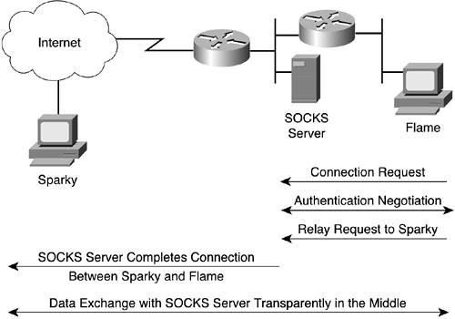
The difficulty with using SOCKS is that somebody has to replace the network system calls with the SOCKS versions. (This process is generally referred to as SOCKS-ification or SOCKS-ifying an application.) Fortunately, most of the common network applications (such as Telnet, FTP, finger, and whois) have already been SOCKS-ified, and many vendors are now including SOCKS support in commercial applications.
Network layer security pertains to security services at the IP layer of the TCP/IP protocol stack. The network layer provides hop-by-hop handling of data packets, where intermediary systems in a network, such as routers, could be involved. At each intermediary system (that is, hop), the data packet is inspected at the IP layer and then forwarded on to the next intermediary system until the final destination is reached. Many years of work have produced a set of standards from the IETF that, collectively, define how to secure services at the IP network layer; these standards are commonly referred to as IPsec.
NOTE
Although network layer inspection is done on a hop-by-hop basis, the encryption/decryption of secured IP network layer packets does not need to happen at each hop.
The IP Security (IPsec) protocol suite comprises a set of standards used to provide privacy and authentication services at the IP layer. The current ratified IPsec standards include four algorithm-independent base specifications:
RFC 2401, “The IP Security Architecture,” defines the overall architecture and specifies elements common to both the IP authentication header (AH) and the IP encapsulating security payload (ESP).
RFC 2402, “The IP Authentication Header (AH),” defines an algorithm-independent mechanism for providing exportable cryptographic authentication without encryption to IPv4 and IPv6 packets.
RFC 2406, “The IP Encapsulating Security Payload (ESP),” defines an algorithm-independent mechanism for providing encryption to IPv4 and IPv6 packets.
RFC 2408, “The Internet Security Association and Key Management Protocol (ISAKMP),” defines procedures and packet formats to establish, negotiate, modify, and delete security associations (SAs). It provides a consistent framework for transferring key and authentication data that is independent of the key generation technique, encryption algorithm, and authentication mechanism. It deliberately separates the details of security association management (and key management) from the details of key exchange. Although this introduces more complexity, it enables the use of different encryption algorithms, authentication mechanisms, and key exchange protocols should more applicable or robust solutions become available for different networking scenarios.
The set of security services IPsec can provide includes access control, connectionless integrity, data origin authentication, rejection of replayed packets (a form of partial sequence integrity), confidentiality (encryption), and limited traffic flow confidentiality. Because these services are provided at the IP layer, they can be used by any higher layer protocol (such as TCP, UDP, ICMP, BGP, and so on).
IPsec uses two protocols, AH and ESP, to provide traffic security, each of which defines a new set of headers to be added to IP datagrams.
The AH protocol is used to ensure the integrity and data origin authentication of the data, including the invariant fields in the outer IP header. It does not provide confidentiality protection. AH provides antireply protection by using sequence numbers and sliding windows to keep track of received packets and packets that are yet to be sent. Replay detection is performed on each IPsec peer by keeping track of the sequence numbers of the packets it has received and advancing a window as it receives newer sequence numbers. It drops any packets with sequence numbers that are outside of the expected window or that are repeated. Note, however, that although the sequence number is always set, replay protection is optional and a receiver may choose to ignore this field.
AH commonly uses a keyed hash function rather than digital signatures, because digital signature technology is too slow and greatly reduces network throughput. HMAC-MD5-96 and HMAC-SHA-96 are required by the protocol specification but keyed MD5 is also commonly supported. AH is an appropriate protocol to use when confidentiality is not required, although in practice it is only rarely deployed. AH has been assigned as IP protocol type 51. Figure 2-29 shows the format of the AH header.

The ESP protocol protects the confidentiality, integrity, and data origin authentication of the data. The original IP headers, protocol headers, and data are all encrypted. Authentication is provided for all fields except the new encapsulation IP header “outside” the ESP Header. Therefore, the scope of the authentication offered by ESP is narrower than it is for AH. Similar to AH, the ESP protocol provides antireply protection by using sequence numbers and sliding windows to keep track of received packets and packets that are yet to be sent. Replay detection is performed on each IPsec peer by keeping track of the sequence numbers of the packets it has received and advancing a window as it receives newer sequence numbers. It drops any packets with sequence numbers that are outside of the expected window or that are repeated. Note, however, that although the sequence number is always set, replay protection is optional and a receiver may choose to ignore this field.
The ESP standard requires implementing DES for its encryption algorithm, although more current implementation tend to also support 3DES and AES. Other algorithms typically supported include RC5, IDEA, Blowfish, CAST, and NULL. For authentication, the ESP standard requires that both the MD5 and SHA-1 algorithms are supported in compliant implementations. ESP NULL encryption is used for providing only authentication services and not confidentiality. If only the upper-layer protocols must be authenticated, ESP authentication is an appropriate choice and is more space efficient than using AH to encapsulate ESP. ESP has been assigned as IP protocol type 50. Figure 2-30 shows the format of the ESP header.

AH and ESP can be used independently or in combination to provide a desired set of security services. For both of these protocols, IPsec does not define the specific security algorithms to use; rather, it provides an open framework for implementing industry-standard algorithms. Although certain algorithms are mandated to be supported, it does not require that they be deployed. A rule of thumb to follow is to use the strongest algorithm with the largest key until you run into performance limitations. There is no reason not to deploy strong security if there are no performance impacts.
Each protocol supports two modes of use:
Transport mode
Tunnel mode
In transport mode, two hosts provide protection primarily for upper-layer protocols; the cryptographic endpoints (where the encryption and decryption take place) are the source and destination of the data packet. In IPv4, a transport mode security protocol header appears immediately after the IP header and before any higher-layer protocols (such as TCP or UDP). Figure 2-31 shows the packet format alterations for AH and ESP in this mode.
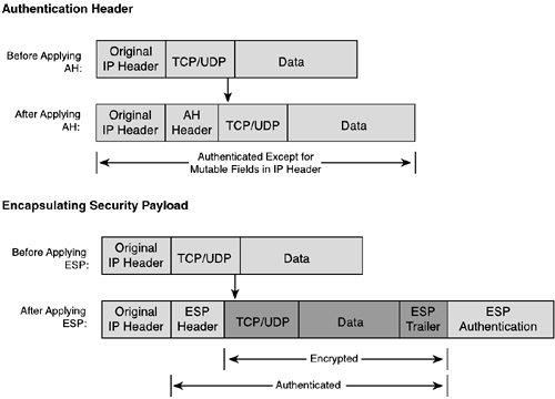
In the case of AH in transport mode, all upper-layer information is protected, and all fields in the IPv4 header excluding the fields that are typically modified in transit. The fields of the IPv4 header that are not included are, therefore, set to zero before applying the authentication algorithm. These fields are as follows:
ToS
TTL
Header Checksum
Offset
Flags
Notice that the IP addresses in the header are included in the integrity check for AH. This means that if the addresses are altered during transit, as is the case for situations where Network Address Translation (NAT) is deployed, the integrity check will fail at the receiving end. NAT is discussed in more detail in the next chapter in the “VPN Security” section.
In the case of ESP in transport mode, security services are provided only for the higher-layer protocols and the data itself, not for the IP header. The authentication value is also sent in the clear because the integrity check value is computed after the encryption process has taken place.
A tunnel is a vehicle for encapsulating packets inside a protocol that is understood at the entry and exit points of a given network. These entry and exit points are defined as tunnel interfaces. Tunnel mode can be supported by data packet endpoints and by intermediate security gateways. In tunnel mode, an “outer” IP header specifies the IPsec processing destination, and an “inner” IP header specifies the ultimate destination for the packet. The source address in the “outer” IP header is the initiating cryptographic endpoint that will get modified as the packet traverses the network to reach its destination cryptographic endpoint; the source address in the “inner” header is the true source address of the packet. The destination address in the “outer” IP header is the destination cryptographic endpoint; the destination address in the “inner” header is the true destination address of the packet. The protocol fields in the “outer” IP header are set to either AH (51) or ESP (50) depending on the protocol used. The respective AH or ESP security protocol header appears after the “outer” IP header and before the “inner” IP header. (See Figure 2-32.)
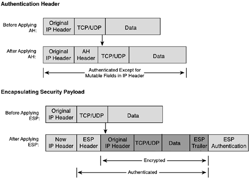
If AH is employed in tunnel mode, portions of the “outer” IP header are given integrity protection (those same fields as for transport mode, described earlier in this section), as well as all of the tunneled IP packet. (That is, all the “inner” IP header is protected as are the higher-layer protocols.) Again, in NAT environments this can be problematic if the IP address translations occur after the IPsec AH services are applied.
If ESP is used, the encryption and authentication protection is afforded only to the tunneled packet, not to the “outer” IP header. The authentication value is also sent in the clear because the integrity check value is computed after the encryption process has taken place.
The concept of a security association (SA) is fundamental to IPsec. An SA is a relationship between two or more entities that describes how the entities will use security services to communicate securely. The SA includes the following:
The ESP encryption algorithm and key(s)
The AH authentication algorithm and key
A shared session key
Mode, tunnel or transport
SA source address
SA lifetime
Because an SA is unidirectional, two SAs (one in each direction) are required to secure typical, bidirectional communication between two entities. The security services associated with an SA can be used for AH or ESP, but not for both. If both AH and ESP protection is applied to a traffic stream, two (or more) SAs are created for each direction to protect the traffic stream.
The SA is uniquely identified by a randomly chosen unique number called the security parameter index (SPI), the protocol (AH or ESP), and the destination IP address . SAs can be manually configured, but it is more common and efficient to use Internet Key Exchange (IKE), the key management protocol, to create the SAs.
The concept of selectors is used to define when to create a SA and what the SA will be used for. It classifies the type of traffic requiring IPsec protection and the kind of protection to be applied. Among the elements a selector can contain to identify a particular traffic flow are the following:
Source IP address—. This can be a specific host, address range (that is, subnet), or a wildcard, which is typically used when the security policy is the same for all packets.
Destination IP address—. This can be a specific host, address range (that is, subnet), or a wildcard, which is typically used when the security policy is the same for all packets. For tunnelled packets, the actual destination is different from the tunnel endpoint, and the IP address of the actual destination is used for policy.
Protocol—. It is possible to define separate security services on a per-protocol basis, such as TCP or UDP.
Upper-layer protocol ports—. It is possible to define separate security services on a per-protocol port number. This can be used for either source or destination ports, or both. For example, one may want to use ESP with NULL encryption and HMAC-SHA1 for routing updates, but use ESP with 3DES and SHA-1 for Telnet and TFTP access to a router.
When a system sends a packet that requires IPsec protection, it uses a security policy database (SPD) to search for a selector that matches the packet criteria and its associated security policy information. If a pre-established SA does not exist, the SA establishment phase begins assuming IKE is being used. If there exists a pre-established SA, the system finds the SA in its database and applies the specified processing and security protocol (AH/ESP), inserting the SPI from the SA into the IPsec header. When the IPsec peer receives the packet, it looks up the SA in its database by destination address, protocol, and SPI, and then processes the packet as required.
NOTE
The order of rules in a security policy database and how vendors use them is extremely important. Typically, the most specific selector match is used. If there is any ambiguity, however, different vendors may handle processing of the packet differently. How a particular vendor uses its SPD should be clarified and understood.
IPsec uses cryptographic keys for authentication/integrity and encryption services. Both manual and automatic distribution of keys is supported.
The lowest (but least desirable) level of key management is manual keying, in which a person manually configures each system by keying material and SA management data relevant to secure communication with other systems. Manual techniques are practical in small, static environments, but they do not scale well. If the number of sites using IPsec security services is small, and if all the sites come under a single administrative domain, manual key management techniques may be appropriate. Manual key management may also be appropriate when only selected communications must be secured within an organization for a small number of hosts or gateways. Manual management techniques often employ statically configured, symmetric keys, although other options also exist.
The default automated key management protocol selected for use with IPsec is the Internet Key Management Protocol (IKMP), sometimes just referred to as the Internet Key Exchange (IKE). IKE authenticates each peer involved in IPsec, negotiates the security policy, and handles the secure exchange of session keys.
NOTE
Although IKE is specified as the public-key-based approach for automatic key management, other automated key distribution techniques can be used. For example, KDC-based systems such as Kerberos and other public key systems such as SKIP can be employed. There exists some confusion with the interchange of terminology between ISAKMP and IKE. This comes mainly from the fact that ISAKMP (RFC 2408) provides a framework for authentication and key exchange, whereas IKE (RFC 2409) is a protocol that specifically defines the negotiation and keying exchange. It may be easier to think of ISAKMP as providing the frame format and IKE filling in the required details.
IKE is a hybrid protocol, combining parts of the following protocols to negotiate and derive keying material for SAs in a secure and authenticated manner. IKE is derived from the following three protocols, as stated in RFC 2409:
ISAKMP (Internet Security Association and Key Management Protocol), which provides a framework for authentication and key exchange but does not define them. ISAKMP is designed to be key exchange independent; that is, it is designed to support many different key exchanges.
Oakley, which describes a series of key exchanges called modes, details the services provided by each (for example, perfect forward secrecy for keys, identity protection, and authentication).
SKEME (Secure Key Exchange Mechanism for the Internet) describes a versatile key exchange technique that provides anonymity, repudiability, and quick key refreshment.
IKE creates an authenticated, secure tunnel between two entities and then negotiates the security association for IPsec. This is performed in two phases. Figure 2-33 shows the two-phase IKE protocol approach.
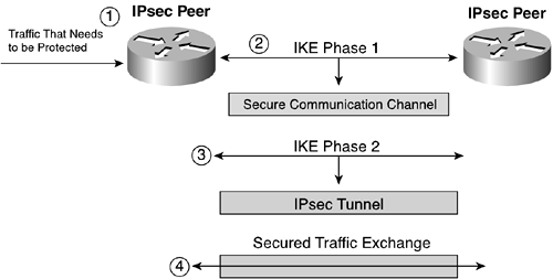
The following steps are carried out:
Traffic is generated or received by one of the IPsec peers that is identified to require IPsec protection to its destination.
IKE phase 1 uses main mode or aggressive mode, explained in more detail later in the “IKE Phase 1” section, to create an IKE SA between the two IPsec peers, which creates a secure communications channel.
IKE phase 2 results in the creation of two IPsec SAs between the two IPsec peers. This pair of unidirectional SAs creates the secure IPsec tunnel.
Data starts passing between the IPsec peers over the established secure IPsec tunnel.
Before describing each of these IKE phases in more detail, it's important to consider the ISAKMP message frame formats. There are some specific terms need to be defined first:
Domain of interpretation (DOI)—. A DOI defines payload formats, exchange types, and conventions for naming security-relevant information such as security policies or cryptographic algorithms and modes. A DOI identifier is used to interpret the payloads of ISAKMP payloads.
Situation—. A situation contains all the security-relevant information that a system considers necessary to decide the security services required to protect the session being negotiated. The situation may include addresses, security classifications, modes of operation (normal versus emergency), and so on.
Proposal—. A proposal is a list, in decreasing order of preference, of the protection suites that a system considers acceptable to protect traffic under a given situation.
All ISAKMP messages are carried in a UDP packet with destination port number 500. An ISAKMP message consists of a fixed header followed by a variable number of payloads. Figure 2-34 shows the ISAKMP header.
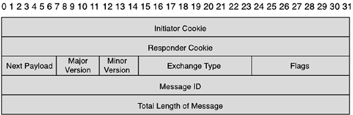
The following fields are included in the header:
Initiator Cookie (8 octets)—. Cookie of entity that initiated the SA establishment, SA notification, or SA deletion.
Responder Cookie (8 octets)—. Cookie of entity that is responding to an SA establishment request, SA notification, or SA deletion.
Next Payload (1 octet)—. Indicates the type of the first payload in the message. Table 2-3 lists the supported payload message types.
Table 2-3. Next Payload Types
Next Payload Type | Value | Description |
|---|---|---|
None | 0 | Indication of last payload in a message. |
Security Association | 1 | Used to negotiate security attributes and to indicate DOI and situation under which negotiation is taking place; a DOI of 0 in phase 1 exchange denotes generic ISAKMP SA, which can be used for any protocol in a phase 2 exchange. |
Proposal | 2 | Specifies the protocol for current negotiation (AH, ESP, and so on) and the number of transforms that will be proposed; also used to send the SPI value. |
Transform | 3 | Consists of a specific security mechanism, or transforms, to be used to secure the communications channel and the SA attributes associated with the specific transform; multiple transform payloads may be specified for a particular proposal. |
Key Exchange | 4 | Used to support a variety of key exchange techniques. |
Identification | 5 | Contains DOI-specific data used to exchange identification information; this information is used for determining the identities of communicating peers and may be used for determining authenticity of information. |
Certificate | 6 | Provides a means to transport certificates or other certificate-related information. |
Certificate Request | 7 | Provides a means to request certificates. |
Hash | 8 | Contains data generated by the hash function selected during the SA establishment exchange; may be used to verify the integrity of the data in an ISAKMP message or for authentication of the negotiating entities. |
Signature | 9 | Contains data generated by the digital signature function selected during the SA establishment exchange; used to verify the integrity of the data in the ISAKMP message, and may be of use for nonrepudiation services. |
Nonce | 10 | Contains random data used to guarantee “freshness” during an exchange and protect against replay attacks. |
Next Payload Type | Value | Description |
|---|---|---|
Notification | 11 | Used to transmit informational data, such as error conditions, to an ISAKMP peer. |
Delete | 12 | A protocol-specific security association identifier that the sender has removed from its SA database and is, therefore, no longer valid; it is an advisory from the initiator to the responder. |
Vendor ID | 13 | Contains a vendor-defined constant that can be used by vendors to identify and recognize remote instances of their implementations. |
Reserved | 14–127 | Not to be used. |
Private Use | 128–255 | Used for vendor specific use. |
Major/Minor Version (4 bits each )—. Indicates the major and minor version of the ISAKMP protocol in use.
Exchange Type (1 octet)—. Indicates the type of exchange being used for the establishment of SAs and keying material. Exchanges define the payload content and ordering of ISAKMP messages during communications between peers.
Flags (1 octet)—. Three flags are specified:
Encryption—. Indication of whether encryption is used
Commit—. Used to ensure that encrypted material is not received prior to completion of SA establishment and can also be used to protect against transmission loss over unreliable networks
Authentication Only—. Intended only for use with an informational exchange using the Notify payload
Message ID (4 octets)—. Random value generated by the initiator of the phase 2 negotiation and used to identify protocol state during phase 2 negotiations.
Length (4 octets)—. Length of total message (header and payloads) in octets.
NOTE
A “cookie” or anticlogging token (ACT) is used to protect against replay attacks. The two cookie fields in the ISAKMP header are used to uniquely identify ISAKMP SAs. The mechanisms to create the cookies are not specified but a recommendation is made to use a hash over the IP source and destination address, the UDP source and destination ports, a locally generated secret random value, the date, and the time.
The messages themselves are constructed by chaining together a series of payloads. Figure 2-35 shows an example of the ISAKMP message format.

In an IKE phase 1 exchange, the two ISAKMP peers establish a secure, authenticated channel with which to communicate. This channel is often referred to as an ISAKMP SA or also an IKE SA. The term IKE SA is used in this text. At the completion of phase 1, only a single SA is established between the two IPsec peers. There are two ways in which this IKE SA can get created: through the use of main mode or aggressive mode, but not both.
NOTE
The terms SA and tunnel can be confusing and are often misused. In this text, the term IKE SA refers to an IKE phase 1 SA that establishes an IKE tunnel. The IKE tunnel is the secure communication channel created upon completion of IKE phase 1. An IPsec SA is a unidirectional IKE phase 2 SA. Two IPsec SAs for bidirectional communication will establish an IPsec tunnel by which the IPsec peers will exchange secure data transmissions.
Most implementations use IPsec main mode to establish the IKE SA. Main mode consists of six message types. The following exchanges take place to establish the IKE SA:
Negotiate IKE policy (message types 1 and 2). Information exchanges in these messages contain attributes that will define the security policy to use for the secure communication channel. In both messages, the SA payload is always first, followed by the proposal payload and one or more transform payloads. The transform payloads contain the proposals for the encryption algorithm, hash algorithm, authentication method, and Diffie-Hellman group number. All messages are carried in UDP packets with a destination UDP port number of 500. The UDP header comprises of a header, an SA payload, and one or more proposals. Message type 1 offers many transform proposals, whereas message type 2 contains only a single transform proposal.
Perform authenticated DH exchange (message types 3 and 4). These messages carry out the Diffie-Hellman (DH) exchange. They contain the key exchange payload, which carries the DH public value, and the nonce payload. Message types 3 and 4 also contain the remote peer's public key hash and a hashing algorithm. When these messages are exchanged, both peers use the DH algorithm to create a shared secret and generate three common session keys:
SKEYID_d—. Used to derive non-ISAKMP keying material
SKEYID_a—. Used to provide data integrity and authentication to IKE messages
SKEYID_e—. Used to encrypt IKE messages
Protect IKE peer's identity (message types 5 and 6). Message type 5 allows the responder to authenticate the initiating device. Message type 6 allows the initiator to authenticate the responder. These messages are encrypted using the agreed upon method from message types 1 and 2 and the shared session keys created by message types 3 and 4. IKE supports multiple mechanisms to perform the authenticated DH exchange:
Preshared keys—. The same key is pre-installed on each host. IKE peers authenticate each other by computing and sending a keyed hash of data that includes the preshared key. If the receiving peer can independently create the same hash using its preshared key, it knows that both parties must share the same secret, and therefore, the other party is authenticated. Preshared key authentication in main mode requires that peers use IP addresses as identification, rather than host names. This restriction is not applicable for aggressive mode.
Public key cryptography—. This is sometimes called an encrypted nonce. Each party generates a pseudo-random number (a nonce) and encrypts it and its ID using the other party's public key. The ability for each party to compute a keyed hash containing the other peer's nonce and ID, decrypted with the local private key, authenticates the parties to each other. This method does not provide nonrepudiation; either side of the exchange could plausibly deny that it took part in the exchange. Currently, only the RSA public key algorithm is supported.
Digital signature—. Each device digitally signs a mutually obtainable hash and sends it to the other party. This method is similar to the public key cryptography approach except that it provides nonrepudiation. Currently, both the RSA public key algorithm and the digital signature standard (DSS) are supported.
NOTE
Both digital signature and public key cryptography require the use of digital certificates to validate the public/private key mapping. IKE allows the certificate to be accessed independently or by having the two devices explicitly exchange certificates as part of IKE.
Figure 2-36 shows the operation of IKE phase 1 main mode.

Aggressive mode is rarely used to establish an IKE SA. Aggressive mode uses only three message types. The first two messages negotiate policy, send respective identities, and exchange DH values and any other data necessary for computing keys (depending on which IKE authentication mechanism is chosen). The second message also authenticates the responder. The third message authenticates the initiator and provides proof of participation in the exchange.
The following is an example of aggressive mode phase 1 using preshared key authentication:
Initiator sends message type 1. The first message sent by the initiator includes the key payload and nonce payload, which is all the information the responder needs to generate the DH shared secret. This message also includes an ID payload and one or more proposals and transform payloads. Note that there is no opportunity to negotiate the DH group; both parties need to know which group to use or fail IKE phase 1 negotiation. Also, the identity of the initiator is sent in the clear. Upon receipt of message 1, the responder generates the DH shared secret and a hash, hash-R.
Responder sends message type 2. The second message, sent by the responder to the initiator, contains the proposal and transform pair to which the responder agreed, the ID payload, the key payload, the nonce payload, and the hash payload, which contains the hash generated by the responder, hash-R. Upon receipt of message 2, the initiator now computes the DH shared secret. It also computes hash-R and compares it to the received hash, which should be equal to validate the responder. Finally, the initiator computes a hash of its own, hash-I.
Initiator sends message type 3. The third message is sent by the initiator and contains the hash payload that contains hash-I. Upon receipt of message 3, the responder computes hash-I and compares it to the received hash. If they are equal, the initiator is authenticated and aggressive mode is completed.
Aggressive mode has limited SA negotioation capabilities. The DH group cannot be negotiated and authentication with public key cryptography cannot be negotiated. In addition, none of the communication is encrypted and identities are sent in the clear. It is more common to use main mode for IKE phase 1 negotiation.
The result of a successful main mode or aggressive mode phase produce three authenticated keys and an agreed upon policy to protect further communication. After the IKE tunnel is successfully established, IKE phase 2 can be initiated to establish the IPsec tunnel.
In phase 2 of the IKE process, SAs are negotiated on behalf of services such as IPsec AH or ESP. In addition, new shared keys are generated for encrypting across the IPsec tunnel. These IPsec shared keys can be derived by using a new DH exchange or by refreshing the shared secret derived from the IKE phase 1 DH exchange by hashing it with a nonce. The first method is slower but provides greater security through perfect forward secrecy. Perfect forward secrecy (PFS) is a property where the compromise of a single key will not compromise subsequent future keys. When used, it forces the IPsec peers to use an additional payload that contain the DH public values during the quick mode exchange. Because there is no mechanism to negotiate a DH group in quick mode, however, the appropriate group must be assumed on both ends for PFS to occur.
NOTE
Diffie-Hellman groups are sometimes referred to as MODP groups in configurations because that's what they are referred to in the standard. Two MODP groups are required to be implemented, group 1 and 2. MODP group 2 has a larger prime and is more secure but the trade-off is that it takes more computing cycles to compute the DH shared secret.
IKE phase 2 uses quick mode to establish the IPsec tunnel. Either peer can initiate the phase 2 exchange. All messages in quick mode are encrypted using the encryption key derived from the phase 1 exchange. All messages are authenticated using the hash payload, which must be the first payload following the ISAKMP header. The hashes are computed over the entire ISAKMP payload (including message ID, port, and protocol, but excluding the generic header).
Quick mode has three different message exchanges. Message 1 from initiator to responder includes the following payloads: hash, SA, proposals and transforms, key exchange and nonce (for requesting PFS), and ID. The ID payload contains the identities on whose behalf the initiator does the negotiation (that is, the selector parameters).
When receiving message 1, the responder verifies the hash to ensure integrity/authentication of the received message. It also looks at the IDs offered by the initiator and compares them to its own policy database to ensure validity. Assuming correct verification, it then replies with message 2, which contains the following payloads: hash, SA, proposal and transform (which contain the acceptable values), key payload and nonce (if PFS is used), and ID.
The initiator verifies the hash sent in message 2 to ensure integrity/authentication of the received message. At this time, both peers have the information needed to create new IPsec session keys. Two session keys are generated by both the responder and the initiator, one for each direction of traffic. Remember that an IPsec SA consists of two unidirectional SAs.
Message 3 is the final message sent by the initiator and consists of the hash payload. The hash included is the hash of the latest two nonces that were sent and, when verified by the responder, acts an integrity/authentication check to complete the IPsec tunnel establishment.
NOTE
The responder can also send a message to the initiator similar to message 3, but it is not a requirement in the specification. Also, computing the new session keys may happen after the third (and possibly fourth) messages are sent to ensure against replay attacks.
Figure 2-37 shows the operation of IKE phase 2 quick mode.

Phase 2 is also used to send reliable and authenticated informational messages.
IKE is an extensible protocol that allows new payloads to be easily added to a new message or new exchanges to be defined. Most of the extensions that have been added to IKE are primarily to improve on inefficiencies when it comes to remote access solutions—specifically, to add support for legacy authentication mechanisms to allow for user authentication (as opposed to device authentication) and to add support for variable addressing environments where the IPsec client may have a dynamic IP address or be afflicted by NAT/Port Address Translation (PAT). Because none of the following are proposed standards and it is unclear what their official standard status will be, only a general description of operation is provided. (Readers interested in more specific detail are encouraged to follow the work in the IPsec working group at http://ietf.org/html.charters/ipsec-charter.html.)
NOTE
NAT and PAT are mechanisms by which a packet's IP addresses or protocol port numbers are modified to be something other than what they originally were. Both are covered in more detail in the Chapter 3 in the “VPN Security” section.
Challenge Response Authentication for Cryptographic Keys (CRACK)—. CRACK is used with either main mode or aggressive mode. The number of messages exhanged depends on the type of legacy authentication method used. The remote client needs to express interest in performing CRACK authentication, and the VPN gateway replies with its certificate, which autheticates the virtual private network (VPN) gateway to the remote client. The remote client then uses legacy authentication for IKE authentication, whereas the VPN gateway uses certificate-based authentication.
Extended Authentication (xauth)—. Xauth occurs after the completion of IKE phase 1 and uses the attribute payload to exchange the remote client authentication information. It is performed on a per-user basis and typically uses a back-end TACACS+ or RADIUS server for scalability. Legacy authentication mechanisms such as username/password, one-time passwords, and CHAP are supported.
Pre-IKE Credential Provisioning Protocol (PIC)—. PIC uses legacy authentication methods to retrieve a certified public key before IKE phase 1 begins. The remote client initiates the establishment of a secure connection using an aggressive mode-like exhange. The VPN gateway responds and initiates EAP, which is the protocol used for authentication requests/responses. The remote client requests credentials from the VPN gateway, which in turn responds with its credentials if authentication is successful. This is now followed by the IKE phase 1 exchange, where certificate-based authentication is used to establish IKE authentication.
Mode configuration (sometimes called config mode)—. Mode configuration is used to allow an IP address to be assigned to a remote client. It occurs after xauth and allows the remote client to request a number of parameters from the VPN gateway (IP address, DNS server address, and so on). The client uses two addresses; the one from the VPN gateway is the source address for packets it inserts into the IPsec tunnel, and the one from the ISP is the source for the tunnel itself.
DHCP configuration—. Another mechanism to solve the remote client address problem is to have the gateway peer act as a Dynamic Host Configuration Protocol (DHCP) relay. For this method, an IKE main mode or aggressive mode SA would first be established between the remote client and gateway peer. This is followed by the remote client establishing a DHCP tunnel quick mode IPsec SA to the gateway peer. DHCP messages are exchanged by the remote client and the DHCP server using the gateway as a DHCP relay. After the address is obtained, the client does a quick mode exchange with the peer gateway to establish the IPsec tunnel using its DHCP address. Note that the gateway needs to snoop the DHCP packet to determine the IP address assigned to the client.
Dead peer detection—. In cases where an IPsec peer is disconnected without sending a delete notification payload (such as in a peer's system crash or network problems), the dead peer detection acts as a mechanism to detect inactive peers. This is often desirable for quick failover or to recover lost resources. A vendor ID payload is added to the IKE main mode exchange to signify support of this mechanism. A time metric is included to specify the time interval to wait before instigating a notify payload message to see whether a peer is alive. If there is a period of inactivity and the time specified has been exceeded, a peer wanting to send traffic sends a notify message to the other peer to see whether it is still alive. If it is alive, the peer achnowledges the notify payload by sending one of its own. Note that the idle time interval is not a negotiable variable and is implementation-specific.
NAT traversal—. NAT is widely deployed in many remote access scenarios and as such there needed to be some way to make IKE work in NAT environments. NAT traversal specifies how to detect the use of NAT and how to handle addressing in those environments. The NAT traversal capability of the remote host is determined by an exchange of vendor ID payloads.
To detect whether the IP address or the port number changes along the path, the peers send the hashes of source/destination IP address and source/destination port numbers to each other. When both ends calculate those hashes and the hashes do not match, it is a good indication that NAT is being used. The hashes are sent as a series of NAT-D (NAT discovery) payloads. Each payload contains one hash, so in the case of multiple hashes, multiple NAT-D payloads are sent. In a normal case, there are only two NAT-D payloads. The NAT-D payloads are included in messages 3 and 4 in main mode and in messages 2 and 3 in aggressive mode. The payload type for the NAT discovery payload is 15.
In main mode, if NAT is detected, the initiator sets both UDP source and destination ports to 4500 for the ID payload. All subsequent packets sent to this peer (including informational notifications) have to be sent on port 4500. If the initiator is behind a NAT, the NAT device maps UDP (4500,4500) to UDP (Y,4500). The responder has to respond with all subsequent IKE packets to this peer using UDP (4500,Y). Aggressive mode uses the same principle.
After IKE phase 1, both ends know whether there is a NAT present between the peers. The decision as to whether to use NAT traversal is negotiated inside the SA payloads of the quick mode. The negotiation of the NAT traversal happens by adding the following two new encapsulation modes:
UDP-encapsulated tunnel (type 3)
UDP-encapsulated transport (type 4)
The original IP source and destination addresses are used in transport mode to incrementally update the TCP/IP checksums so that they will match after the NAT transform. (The NAT device cannot do this, because the TCP/IP checksum is inside the UDP-encapsulated IPsec packet.) These original addresses are sent in quick mode using NAT-OA (NAT original address) payloads, which have a type value of 16. The NAT-OA payloads are sent in message 1 and message 2 of quick mode if UDP-encapsulated transport mode is requested.
The use of NAT traversal negates the value of authentication mechanisms based on IP addresses. For IKE main mode, this means that preshared key authentication cannot be used without group shared keys for everybody behind the NAT box, creating a large security risk. If using main mode, another authentication mechanism should be used.
NOTE
Some IPsec-aware NAT devices have deployed proprietary solutions other than NAT traversal. These may not change the IKE source port 500 even if there are multiple clients behind the NAT. A common alternative method is to use IKE cookies to demultiplex traffic instead of using the source port.
For NAT traversal to work with ESP traffic, an additional specification was written. AH was originally also included but was omitted in later versions due to its limited use in actual deployments. The “UDP Encapsulation of IPsec Packets” specification defines methods to encapsulate and decapsulate IPsec ESP packets inside UDP packets. The UDP port numbers are the same as used by IKE traffic. Figure 2-38 shows both transport mode and tunnel mode encapsulation.

In the past few years, extensive work has been done to create a successor to the original IKE specification; this successor is named IKEv2. IKEv2 intends to preserves most of the features of the original IKE, including identity hiding, PFS, two phases, and cryptographic negotiation, while greatly redesigning the protocol for efficiency, security, robustness, and flexibility. At the time of this writing, the work is still in progress, but the main points that have so far been agreed upon are as follows:
An initial handshake exchange allows peers to negotiate cryptographic algorithms, mutually authenticate, and establish a session key, creating an IKE SA. This usually consists of two request/response pairs where the first pair negotiates cryptographic algorithms and does a Diffie-Hellman exchange, and the second pair is encrypted and integrity-protected with keys based on the Diffie-Hellman exchange. In the second pair of messages, the peers also send their identities and prove it by using an integrity check based on the secret associated with their identity (private key or shared secret key) and the contents of the first pair of messages in the exchange.
A first IPsec SA is established during the initial IKE SA creation. The IPsec SAs are referred to as child SAs. The exchange to establish a child SA consists of an optional Diffie-Hellman exchange (for PFS), nonces (to establish unique keys), and negotiation of traffic selector values, which indicate what addresses, ports, and protocol types are to be transmitted over that child SA.
After the initial handshake, additional requests can be initiated by either peer and consist of either informational messages or requests to establish another child SA. Informational messages include such things as null messages for detecting peer aliveness and deletion of SAs.
An initiator can specify a responder's identity. This enables the use of multiple services where a specific IP address may be associated with multiple identities, each with different authentication credentials.
Denial-of-service prevention is incorporated using a “stateless cookie.” The mechanism deploys two extra messages that are short enough to avoid fragmentation and avoids an attack based on fragmentation.
Cryptographic negotiation is based on “suites.” All parameters are encoded into a single suite number, and negotiation consists of offering one or more suites and having the other side choose.
Addressing assignment issues are solved by incorporating the mode configuration extension into IKEv2.
NAT traversal is incorporated into IKEv2 and is based on the NAT traversal extensions for the original IKE.
Identities hiding from passive attackers is supported for both parties. (This assumes that identities are not based on fixed IP addresses; if they are based on fixed IP addresses, the identity is not hidden.)
Authentication mechanisms supported are preshared keys and public signature keys. Because with the latter one side has to reveal its identity first, if it is communicating with an active attacker, it will reveal its identity to that attacker. IKEv2 has the initiator reveal its identity first.
Legacy authentication mechanisms are supported through the use of EAP.
IPsec is designed to protect IP packets from modification or snooping and is an important technology for securing traffic traversing the network. It has been widely implemented and is a vital component in deploying virtual private networks.
This section discusses security technologies created to address link-layer protocols. Some of the authentication technologies discussed earlier in this chapter are integrated into these solutions. Link-layer security technologies deal primarily with tunnels. Virtual private dialup networks (VPDNs) enable large enterprises to extend their private networks across dialup lines. Instead of incurring large costs to ensure security by dialing in to a campus site from anywhere in the world or lessening security by dialing in locally and using the Internet as the transport to get to the main enterprise campus, link-layer tunneling technologies enable remote sites and users to securely connect to the enterprise infrastructure using local dialup access to the Internet.
Three similar protocols currently exist to accomplish this goal:
The Layer 2 Forwarding (L2F) protocol was created by Cisco Systems. Although it is being replaced by L2TP, it is discussed here because it is still used in some environments. L2F permits the tunneling of the link layer—that is, High-Level Data Link Control (HDLC), async HDLC, or Serial Line Internet Protocol (SLIP) frames—of higher-level protocols. Figure 2-39 shows the format of the tunneled packet.

Using such tunnels, it is possible to decouple the location of the initial dialup server from the location at which the dialup protocol connection is terminated and access to the network is provided. These tunnels also enable applications that require support for privately addressed IP, IPX, and AppleTalk dialup using SLIP/PPP across the existing Internet infrastructure.
Figure 2-40 shows a sample virtual dialup scenario for L2F. The following steps are carried out:
The remote user initiates a PPP connection to an ISP over the Public Switched Telephone Network (PSTN) (or natively over ISDN).
The NAS accepts the connection, and the PPP link is established.
The ISP authenticates the end system or user using CHAP or PAP.
NOTE
If permitted by the organization's security policy, the authorization of the dial-in user at the NAS can be performed only on a domain name within the Username field and not on every individual username. This setup can substantially reduce the size of the authorization database. If a virtual dialup service is not required, traditional access to the Internet may be provided by the NAS. All address assignment and authentication would be performed locally by the ISP in this situation.
NAS initiates the L2F tunnel to the desired corporate gateway.
The corporate gateway authenticates the remote user and either accepts or rejects the tunnel.
NOTE
The initial setup notification may include the authentication information required to allow the corporate gateway to authenticate the user and decide to accept or decline the connection. In the case of CHAP, the setup packet includes the challenge, username, and raw password; for PAP, the setup packet includes the username and cleartext password. The corporate gateway can be configured to use this information to complete its authentication, avoiding an additional cycle of authentication.
The corporate gateway confirms acceptance of the call and L2F tunnel.
NOTE
If the corporate gateway accepts the connection, it creates a virtual interface for PPP in a manner analogous to what it would use for a direct-dialed connection. With this virtual interface in place, link-layer frames can now pass over this tunnel in both directions. Frames from the remote user are received at the NAS, stripped of any link framing or transparency bytes, encapsulated in L2F, and forwarded over the appropriate tunnel.
The corporate gateway accepts these frames, strips L2F, and processes them as normal incoming frames for the appropriate interface and protocol. The virtual interface behaves very much like a hardware interface, except that the hardware in this case is physically located at the ISP NAS. The reverse traffic direction behaves analogously, with the corporate gateway encapsulating the packet in L2F, and the NAS stripping L2F encapsulation before transmitting it out the physical interface to the remote user.
The corporate gateway exchanges PPP negotiations with the remote user. Because the remote user has become just another dialup client of the corporate gateway access server, client connectivity can now be managed using traditional mechanisms with respect to further authorization, address negotiation, protocol access, accounting, and filtering.
End-to-end data is tunneled between the remote user and the corporate gateway.
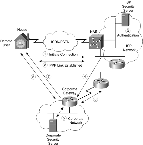
The Point-to-Point Tunneling Protocol (PPTP) was initiated by Microsoft and after additional vendor input became an informational standard in the IETF, RFC 2637. It is a client/server architecture that allows PPP to be tunneled through an IP network and decouples functions that exist in current NASs.
Traditionally, the following functions are implemented by a NAS:
Providing a physical native interface to PSTN or ISDN networks and controlling external modems or terminal adapters
Providing the logical termination of a PPP LCP session
Participating in PPP authentication protocols
Providing channel aggregation and bundle management for PPP multilink protocol
Performing the logical termination of various PPP network control protocols (NCPs)
Performing multiprotocol routing and bridging between NAS interfaces
PPTP divides these functions between two entities:
PPTP access concentrator (PAC)—. This device is attached to one or more PSTN or ISDN lines capable of PPP operation and of handling the PPTP protocol.
PPTP network server (PNS)—. This device handles the server side of the PPTP protocol. Because PPTP relies completely on TCP/IP and is independent of the interface hardware, the PNS may use any combination of IP interface hardware, including LAN and WAN devices.
The PAC is responsible for providing the physical interface to the PSTN and ISDN networks and for providing the logical termination for PPP LCP sessions. Participation in PPP authentication protocols can be part of either the PAC or the PNS. The PNS is responsible for channel aggregation, logical termination of PPP NCPs, and multiprotocol routing and bridging between NAS interfaces. PPTP is the protocol used to carry PPP protocol data units (PDUs) between the PAC and PNS; in addition, call control and management issues are addressed by PPTP.
PPTP is connection-oriented. The PNS and PAC maintain connection information for each user attached to a PAC. A session is created when an end-to-end PPP connection is attempted between a dialup user and the PNS. The datagrams related to a session are sent over the tunnel between the PAC and the PNS.
A tunnel is defined by a PNS-PAC pair. The tunnel carries PPP datagrams between the PAC and the PNS. Many sessions are multiplexed on a single tunnel. A control connection operating over TCP manages the establishment, release, and maintenance of sessions and of the tunnel itself.
There are two parallel components of PPTP, as described in the following sections:
A control connection must be established between the PNS-PAC pair before PPP tunneling can occur between them. The control connection is a standard TCP session over which PPTP call control and management information is passed. The TCP session for the control connection is established by initiating a TCP connection to port 1723. The control session is logically associated with, but separate from, the sessions being tunneled through a PPTP tunnel.
The first set of control connection messages is used to maintain the control connection itself. The control connection is initiated by either the PNS or the PAC after they establish the underlying TCP connection. The control connection is responsible for the establishment, management, and release of sessions carried through the tunnel. It is the means by which a PNS is notified of an incoming call at an associated PAC, as well as the means by which a PAC is instructed to place an outgoing dial call. After the control connection is established, the PAC or PNS may initiate sessions by requesting outbound calls or by responding to inbound requests. The control connection itself is maintained by keepalive echo messages.
PPTP requires the establishment of a tunnel for each communicating PNS-PAC pair. This tunnel is used to carry all user session PPP packets for sessions involving a given PNS-PAC pair. PPTP uses an extended version of to carry user PPP packets. These enhancements allow for low-level congestion and flow control to be provided on the tunnels used to carry user data between PAC and PNS. Many sessions are multiplexed on a single tunnel. A control connection operating over TCP controls the establishment, release, and maintenance of sessions and of the tunnel itself.
The user data carried by the PPTP protocol is PPP data packets. PPP packets are carried between the PAC and the PNS, encapsulated in GRE packets, which in turn are carried over IP. The encapsulated PPP packets are essentially PPP data packets without any media-specific framing elements.
Figure 2-41 shows the general packet structure that is transmitted over the tunnels between a PAC and a PNS.
The GRE header used in PPTP is modified slightly from that specified in RFC 1701. The main difference is the addition of a new Acknowledgment Number field, used to determine whether a particular GRE packet or set of packets has arrived at the remote end of the tunnel. This acknowledgment capability is not used in conjunction with any retransmission of user data packets. It is used instead to determine the rate at which user data packets are to be transmitted over the tunnel for a given user session. Figure 2-42 shows the format of this GRE header.
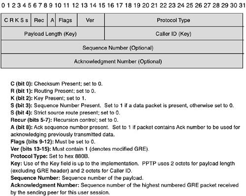
NOTE
There currently exist three different GRE specifications in the IETF. RFC 2784 obsoleted RFC 1701, although both implementations are deployed in a variety of networks. There is also a newer version, RFC 2890, which vendors are starting to implement.
The GRE packets forming the tunnel itself are not cryptographically protected and therefore offer no security for the PPTP packets. PPTP control channel messages are neither authenticated nor integrity protected. The security of user data passed over the tunneled PPP connection is addressed by PPP, as is authentication of the PPP peers.
Because both L2F and PPTP provide similar functionality, Cisco and Microsoft, along with other vendors, have collaborated on a single standard which is now called Layer 2 Tunneling Protocol (L2TP). This protocol is specified in RFC 2661 and is commonly referred to as L2TPv2. L2TP has since been adopted for tunneling a number of other layer protocols, and work is in progress to specify a new version of the protocol, L2TPv3, which will provide greater modularity and a clearer separation from PPP. Because the L2TPv3 work is still in progress, however, this discussion focuses on the operational aspects of L2TPv2.
L2TP addresses the following end-user requirements:
End-system transparency. Neither the remote end system nor the home site hosts should require any special software to use this service in a secure manner.
Authentication as provided by the dialup PPP CHAP, PAP, EAP, or through other dialogs boxes (such as a textual exchange on V.120 before starting PPP). This includes TACACS+ and RADIUS solutions and also supports smart cards and one-time passwords. The authentication should be manageable by the user independently of the ISP.
Addressing should be as manageable as dedicated dialup solutions. The address should be assigned by the home site and not by the ISP.
Authorization should be managed by the home site as it would be in a direct dialup solution.
Accounting should be performed both by the ISP (for billing purposes) and by the user (for chargeback and auditing purposes).
In a way similar to PPTP, L2TP defines two entities:
L2TP access concentrator (LAC)—. This device is attached to the switched network fabric (for example, PSTN or ISDN) or co-located with a PPP end system capable of handling L2TP. The LAC only has to implement the media over which L2TP is to operate to pass traffic to one or more LNSs. The LAC may tunnel any protocol carried within PPP. The LAC is the initiator of incoming calls and the receiver of outgoing calls.
L2TP network server (LNS)—. This server operates on any platform capable of PPP termination. The LNS handles the server side of the L2TP protocol. Because L2TP relies on only the single media over which L2TP tunnels arrive, the LNS may have only a single LAN or WAN interface yet be able to terminate calls arriving at any LAC's full range of PPP interfaces (async, synchronous ISDN, V.120, and so on). The LNS is the initiator of outgoing calls and the receiver of incoming calls.
To be able to initiate an incoming or outgoing call, an end-to-end PPP connection must first be established between a remote system and the LNS, followed by an exchange of control messages between the LAC-LNS pair to establish the corresponding control connection. When the control connection is in place, sessions can be established as triggered by incoming or outgoing call requests. The sessions carry the L2TP payload packets, which are used to transport L2TP-encapsulated PPP packets between the LAC-LNS pair.
NOTE
For this section, the term tunnel is defined as consisting of a control connection and zero or more L2TP sessions. The tunnel carries encapsulated PPP datagrams and control messages between the LAC and the LNS.
Both the control messages and payload packets use the same L2TP header format, as shown in Figure 2-43.

The fields for the header are as follows:
Type (T)—. Indicates the type of message. It is set to 0 for a data message and 1 for a control message.
Length (L)—. Set to 1 if the Length field is present; must be 1 for a control message.
x bits—. These are reserved for future extensions and are set to 0 on outgoing messages and ignored on incoming messages.
Sequence (S)—. If it is set to 1, the Ns and Nr fields are present; must be set to 1 for control messages.
Offset (O)—. If it is set to 1, the Offset Size field is present; must be set to 0 for control messages.
Priority (P)—. If it is set to 1, this data message should receive preferential treatment in its local queuing and transmission; it is only for use with data messages. The P bit must be set to 0 for all control messages.
Version—. Indicates the version of the L2TP data message header.
Length—. Indicates the total length of the message in bytes.
Tunnel ID—. Indicates the identifier for the control connection. L2TP tunnels are named by identifiers that have local significance only; the tunnel ID in each message is that of the intended recipient, not the sender. Tunnel IDs are selected and exchanged as assigned tunnel ID AVPs (address-value pairs) during the creation of a tunnel.
Session ID—. Indicates the identifier for a session within a tunnel; L2TP sessions are named by identifiers that have local significance only. Session ID in each message is that of the intended recipient, not the sender. Session IDs are selected and exchanged as assigned session ID AVPs during the creation of a session.
Ns—. Indicates the sequence number for this data or control message, beginning at 0 and incrementing for each message sent.
Nr—. Indicates the sequence number expected in the next control message to be received; in data messages, Nr is reserved and, if present (as indicated by the S bit), is ignored upon receipt.
Offset Size—. If this field is present, it specifies the number of bytes past the L2TP header at which the payload data is expected to start. The actual data within the offset padding is undefined. If the Offset field is present, the L2TP header ends after the last octet of the offset padding.
The control connection is the initial connection that must be established between a LAC and LNS before sessions can be brought up. Establishment of the control connection includes securing the identity of the peer, as well as identifying the peer's L2TP version, framing, bearer capabilities, and so on. The control messages are responsible for the establishment, management, and release of call sessions, as well as the status of the tunnel itself. Control messages are the means by which an LNS is notified of an incoming call at an associated LAC, as well as the means by which a LAC is instructed to place an outgoing call.
The control connection can be initiated by either the LNS or the LAC. During this phase, an optional CHAP-like mechanism is used for tunnel authentication. To participate in the authentication, a single shared secret must exist between the LAC and LNS.
Following the creating of the control channel, the LNS and LAC configure the tunnel parameters. This is done through a series of AVPs. The control messages include a mechanism to indicate to the receiving peer whether the contents of the AVP are encrypted or present in cleartext. This is accomplished through the combination of an MD5 hash and the XOR function. This feature is useful for hiding sensitive control message data such as user passwords or user IDs. It requires the existence of a shared secret between the LAC and LNS. The shared secret is the same secret used for tunnel authentication.
When the control message exchange is complete, either the LAC may initiate sessions by indicating inbound requests, or the LNS can request outbound calls. If both ends of the tunnel have the capability to act as an LAC and LNS concurrently, nothing prohibits the establishment of incoming or outgoing calls from both sides of the same tunnel.
A keepalive mechanism is employed by L2TP through the use of hello packets to differentiate tunnel outages from extended periods of no control or data activity on a tunnel.
After a successful L2TP control connection setup, individual sessions can be created to carry user-session PPP packets for sessions involving a given LNS-LAC pair. A session can be established by either a LAC or an LNS. Unlike control connection establishment, session establishment is directional with respect to the LAC and LNS. The LAC requests the LNS to accept a session for an incoming call, and the LNS requests the LAC to accept a session for placing an outgoing call. The Call ID field in the L2TP header indicates the session to which a particular PPP packet belongs. In this manner, PPP packets are multiplexed and demultiplexed over a single tunnel between a given LNS-LAC pair. The Call ID field value is established during the exchange of call setup control messages.
When tunnel establishment is complete, PPP frames from the remote system are received at the LAC, stripped of cyclic redundancy check (CRC), link framing, and transparency bytes, encapsulated in L2TP, and forwarded over the appropriate tunnel. The LNS receives the L2TP packet and processes the encapsulated PPP frame as if it were received on a local PPP interface.
Unlike the L2TP control channel, the L2TP data channel does not use sequence numbers to retransmit lost data messages. Rather, data messages may use sequence numbers to detect lost packets and/or restore the original sequence of packets that may have been reordered during transport.
It is legal for multiple session tunnels to exist between a given LNS-LAC pair. With multiple tunnels, each tunnel can be used for a single user session, and the tunnel media (an SVC, for instance) can have specific quality of service (QoS) attributes dedicated to a given user. L2TP provides a tunnel identifier so that individual tunnels can be identified, even when arriving from a single source LAC or LNS.
L2TP uses the well-known UDP port 1701. The entire L2TP packet, including payload and L2TP header, is sent within a UDP datagram. The initiator of an L2TP tunnel picks an available source UDP port and sends to the desired destination at port 1701. The recipient picks a free port on its own system (which may or may not be port 1701) and sends its reply to the initiator's UDP port, setting its own UDP source port to the free port it found.
It is legal for a peer's IP address or UDP port used for a given tunnel to change over the life of a connection (for example, when a peer with multiple IP interfaces responds to a network topology change). Responses should reflect the last source IP address and the UDP port for that tunnel ID.
Figure 2-44 shows a sample L2TP scenario of a generic Internet arrangement with PSTN access (that is, async PPP using modems) and ISDN access (synchronous PPP access). Remote users (either async or ISDN PPP) access the corporate LAN as if they had dialed in to the LNS, although their physical dialup is through the ISP NAS (acting as the LAC).

The steps needed to complete the PPP tunnel are as follows:
The remote user initiates a PPP connection to an ISP using either the PSTN or ISDN.
The LAC accepts the connection, and the PPP link is established. L2TP also permits the LAC to check with an LNS after call indication before accepting the call. This is useful when Dialed Number Information String (DNIS), an indication to the receiver of a call as to what phone number the caller used to reach it or Calling Line Identification (CLID) information is available in the incoming call notification.
The ISP can now undertake a partial authentication of the end system or user. Only the Username field is interpreted to determine whether the user requires a virtual dialup service. Alternatively, the ISP may have already determined the target LNS from DNIS. If the LNS is willing to accept tunnel creation without any authentication of the caller, the LAC may tunnel the PPP connection without ever having communicated with the remote user.
If no tunnel connection currently exists to the desired LNS, one is initiated. L2TP is designed to be largely insulated from the details of the media over which the tunnel is established; L2TP requires only that the tunnel media provide packet-oriented, point-to-point connectivity. Obvious examples of such media are UDP, Frame Relay PVCs, and X.25 VCs.
After the tunnel exists, an unused slot within the tunnel (a call ID), is allocated and a connect indication is sent to notify the LNS of this new dialup session. The LNS either accepts the connection or rejects it.
If the LNS accepts the connection, it creates a virtual interface for PPP in a manner analogous to what it would use for a direct-dialed connection. With this virtual interface in place, link-layer frames can now pass through the tunnel in both directions. Frames from the remote user are received at the point of presence (POP); stripped of CRC, link framing, and transparency bytes; encapsulated in L2TP; and forwarded over the appropriate tunnel.
The LNS accepts these frames, strips L2TP, and processes them as normal incoming frames for the appropriate interface and protocol. The virtual interface behaves very much like a hardware interface, with the exception that the hardware in this case is physically located at the ISP POP. The other direction behaves analogously, with the LNS encapsulating the packet in L2TP, and the LAC stripping L2TP before transmitting it out the physical interface to the remote user.
At this point, the connectivity is a point-to-point PPP session whose endpoints are the remote user's networking application on one end and the termination of this connectivity into the LNS's PPP support on the other. Because the remote user has become just another dialup client of the LNS, client connectivity can now be managed using traditional mechanisms with respect to further authorization, protocol access, and packet filtering.
L2TP is inherently a link-layer tunneling protocol and has no capability to provide security services to the data being sent across the L2TP tunnel. Although the tunnel endpoints may optionally authenticate each other, the mechanism is not designed to provide an authentication beyond tunnel establishment. Securing L2TP requires that the underlying transport make available encryption, integrity, and authentication services for all L2TP traffic. IPsec in transport mode is used to provide the security services for L2TP over IP traffic and has been standardized in the IETF (RFC 3193).
PPP over Ethernet (PPPoE) is defined in RFC 2516 and provides the means to encapsulate PPP packets over the Ethernet link layer. It enables several hosts on a single subnet to be connected to a remote access concentrator via a simple bridging access device. This model is mostly used in ADSL environments to provide access control, billing, and type of service on a per-user, rather than a per-site, basis.
PPPoE has two distinct stages: a discovery stage and a PPP session stage. The discovery process identifies the Ethernet MAC address of the remote access concentrator and establishes a unique PPPoE session identifier. Whereas PPP defines a peer-to-peer relationship, the discovery process is inherently a client/server relationship. Multiple access servers may be discovered, but only one can be selected. Upon completion of a successful discovery process, both the client host and the selected access concentrator have the information they will use to build their PPP connection over Ethernet.
The PPP session can now be established. When the PPPoE session begins, PPP data is sent as in any other PPP encapsulation. The PPPoE payload contains a PPP frame that begins with the PPP protocol ID. All Ethernet packets are unicast.
Figure 2-45 shows the PPPoE frame format.

The following fields are defined:
Destination MAC Address—. Contains either a unicast Ethernet destination address or the Ethernet broadcast address (0xffffffff). For discovery packets, the value is a unicast or broadcast. For PPP session traffic, this field must contain the peer's unicast address as determined from the discovery stage.
Source MAC Address—. Contains the Ethernet MAC address of the source device.
Type—. Set to either 0x8863 (discovery stage) or 0x8864 (PPP session stage).
Version—. Set to 0x1 for the PPPoE specification in RFC 2516.
Code—. Used for the discovery and PPP session stages.
Session ID—. Set to 0 for discovery packets; for each session, it stays the same (the value assigned in the discovery process).
Length—. Indicates the length of the PPPoE payload, excluding the length of the Ethernet or PPPoE headers.
PPPoE is a very simple protocol and only provides a mechanism to tunnel PPP traffic over Ethernet. It does not provide any security services to the traffic that is encapsulated. In addition, PPPoE enables other listeners on the same Ethernet to eavesdrop on the wire and “see” the PPP frames. Therefore, any authentication schemes using cleartext passwords, such as PPP PAP, should be avoided.
Many security protocols rely on public key cryptography to provide services such as confidentiality, data integrity, data origin authentication, and nonrepudiation. The purpose of a Public Key Infrastructure (PKI) is to provide trusted and efficient key and certificate management to support these protocols.
A PKI is defined by the “Internet X.509 Public Key Infrastructure PKIX Roadmap,” a work in progress document, as follows:
The set of hardware, software, people, policies, and procedures needed to create, manage, store, distribute, and revoke certificates based on public key cryptography.
A PKI consists of the following five types of components (taken from NIST Special Publication 800-15, “Minimum Interoperability Specification for PKI Components, Version 1,” September 1997, by William Burr, Donna Dodson, Noel Nazario, and W. Timothy Polk):
Certification authorities (CAs) that issue and revoke certificates
Organizational registration authorities (ORAs) that vouch for the binding between public keys, certificate holder identities, and other attributes
Certificate holders that are issued certificates and that can sign digital documents
Clients that validate digital signatures and their certification paths from a known public key of a trusted CA
Repositories that store and make available certificates and certificate revocation lists (CRLs)
The functions of a PKI can be summarized as follows:
Registration—. The process whereby a subject first makes itself known to a CA (directly or through a registration authority [RA]) before that CA issues a certificate or certificates for that subject.
Initialization—. The point at which the user or client system gets the values it needs to begin communicating with the PKI. For example, initialization can involve providing the client system with the public key or the certificate of a CA after a client request has been received, or generating the client system's own public/private key pair.
Certification—. The process in which a CA issues a certificate for a subject's public key and returns that certificate to the subject (or posts that certificate in a repository).
Key pair recovery—. If the CA has generated and issued the key pair, the user's private key can be either backed up by a CA or by a separate key backup system. If a user or his/her employer wants to recover these backed-up key materials, the PKI must provide a system that permits the recovery without providing an unacceptable risk of compromise of the private key.
Key generation—. Depending on the CA's policy, the private/public key pair can either be generated by the user in his local environment, or be generated by the CA. In the latter case, the key material may be distributed to the user in an encrypted file or on a physical token (such as a smart card or PCMCIA card).
Key update—. All key pairs must be updated regularly—that is, replaced with a new key pair—and new certificates must be issued. This happens in two cases: normally, when a key has passed its maximum usable lifetime; and exceptionally, when a key has been compromised and must be replaced.
Cross-certification—. A certificate is issued by one CA to another CA; the certificate contains a public CA key associated with the private CA signature key used for issuing certificates. Typically, a cross-certificate is used to allow client systems and end entities in one administrative domain to communicate securely with client systems and end users in another administrative domain.
Revocation—. When a certificate is issued, it is expected to be in use for its entire validity period. However, various circumstances may cause a certificate to become invalid before the expiration of the validity period. Such circumstances include change of name, change of association between subject and CA (for example, an employee terminates employment with an organization), and compromise or suspected compromise of the corresponding private key. Under such circumstances, the CA must revoke the certificate.
Figure 2-46 shows an example of two entities communicating with a common CA, using digital certificates to validate public keys.
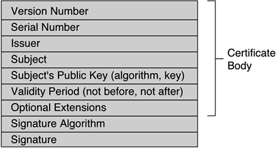
Both routers and the CA have a public/private key pair. Initially, the CA has to enroll an X.509v3 certificate for both routers in a secure manner. Also, both routers must receive a copy of the CA's public key in a secure manner. Now, if the router in New York has traffic to send to the router in Paris and wants authentication, confidential delivery of the data, the following steps must occur:
The New York router sends a request to the CA (for example, it makes an LDAP query) to obtain the Paris router's public key.
The CA sends the Paris router's certificate, signed with its own private key.
The New York router verifies the signature with the CA's public key to validate the Paris router's public key.
The Paris router sends a request to the CA to obtain the New York router's public key.
The CA sends the New York router's certificate, signed with its own private key.
The Paris router verifies the signature with the CA's public key to validate the New York router's public key.
Now, both routers have each other's public key and can use public key encryption to send authenticated, confidential data.
Typically, an authenticated Diffie-Hellman exchange, as explained in Chapter 1, “Basic Cryptography,” would take place to derive a shared key for secret key encryption because secret key encryption is usually used for bulk data encryption (it is much faster computationally).
Users of public-key-based systems must be confident that, any time they rely on a public key, the associated private key is owned by the subject with which they are communicating. (This applies whether an encryption or digital signature mechanism is used.) This confidence is obtained through the use of public key certificates, which are data structures that bind public key values to subjects. The binding is achieved by having a trusted CA verify the subject's identity and digitally sign each certificate. The purpose of a CA, therefore, is to bind a public key to the common name of the certificate and, thus, assure third parties that some measure of care has been taken to ensure that this binding is valid.
The CA paradigm essentially relies on an authentication chain that ends in a CA that eventually certifies itself. The problem is shifted from a local perspective to a global perspective, with the whole chain depending on one final link.
A certificate has a limited valid lifetime, indicated in its signed contents. Because a certificate's signature and timeliness can be independently checked by a certificate-using client, certificates can be distributed using untrusted communications and server systems and can be cached in unsecured storage in certificate-using systems.
Certificates are used in the process of validating signed data. Specifics vary according to which algorithm is used, but the general process works as follows:
The recipient of signed data verifies that the claimed identity of the user is in accordance with the identity contained in the certificate.
The recipient validates that no certificate in the path has been revoked (for example, by retrieving a suitably current CRL or querying an online certificate status responder), and that all certificates were within their validity periods at the time the data was signed.
The recipient verifies that the data does not claim to have any attributes for which the certificate indicates that the signer is not authorized.
The recipient verifies that the data has not been altered since it was signed by using the public key in the certificate.
If all of these checks pass, the recipient can accept that the data was signed by the purported signer. The process for keys used for encryption is similar to the preceding process.
NOTE
It can, of course, be possible that data was signed by someone very different from the signer (for example, if the purported signer's private key was compromised). Security depends on all parts of the certificate-using system, including, but not limited to, the following:
The physical security of the place in which the computer resides
Personnel security (the trustworthiness of the people who actually develop, install, run, and maintain the system)
The security provided by the operating system on which the private key is used
The security provided the CA
A failure in any one of these areas can cause the entire security system to fail.
The X.509 standard constitutes a widely accepted basis for a PKI infrastructure, defining data formats and procedures related to the distribution of public keys using certificates digitally signed by CAs. RFC 1422 specified the basis of an X.509-based PKI, targeted primarily at satisfying the needs of Internet privacy-enhanced mail (PEM). Since RFC 1422 was issued, application requirements for an Internet PKI have broadened tremendously, and the capabilities of X.509 have greatly advanced. Much work is being done to use digital certificates in web, e-mail, and IPsec applications. The current standards define the X.509 version 3 certificate and version 2 CRL.
The information contained in the certificate must be uniform throughout the PKI. The current proposed standard to provide a common baseline for the Internet uses a X.509v3 certificate format. (See Figure 2-47.)

Every certificate contains three main fields:
The body of the certificate
The signature algorithm
The signature itself
The body of the certificate contains the version number, the serial number, the names of the issuer and subject, a public key associated with the subject, and an expiration date (not before and not after a specified time/date); some certificate bodies contain extensions, which are optional unique identifier fields that associate additional attributes with users or public keys. The signature algorithm is the algorithm used by the CA to sign the certificate. The signature is created by applying the certificate body as input to a one-way hash function. The output value is encrypted with the CA's private key to form the signature value, as shown in Figure 2-48.
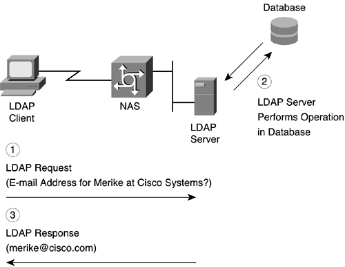
When a certificate is issued, it is expected to be in use for its entire validity period. However, various circumstances may cause a certificate to become invalid before the validity period expires. Such circumstances might include a change of name, a change of association between the subject and CA (for example, an employee terminates employment with an organization), and the compromise or suspected compromise of the corresponding private key. Under such circumstances, the CA should revoke the certificate.
X.509 defines one method of certificate revocation. This method requires each CA to periodically issue a signed data structure called a certificate revocation list (CRL). A CRL is a time-stamped list that identifies revoked certificates. The CRL is signed by a CA and made freely available in a public repository. Each revoked certificate is identified in a CRL by its certificate serial number. When a certificate-using system uses a certificate (for example, to verify a remote user's digital signature), that system not only checks the certificate signature and validity but also acquires a suitably recent CRL and checks that the certificate serial number is not on that CRL.
The meaning of “suitably recent” can vary with local policy, but it usually means the most recently issued CRL. A CA issues a new CRL on a regular basis (hourly, daily, or weekly). CAs may also issue CRLs at unpredictable time intervals. (If an important key is deemed compromised, for example, the CA may issue a new CRL to expedite notification of that fact, even if the next CRL does not have to be issued for some time.)
NOTE
A problem of unpredictable CRL issuance is that end entities may not know that a new CRL has been issued and, therefore, may not retrieve it from a repository.
An entry is added to the CRL as part of the next update following notification of revocation. An entry can be removed from the CRL after it appears on one regularly scheduled CRL issued beyond the revoked certificate's validity period.
An advantage of the CRL revocation method is that CRLs can be distributed in exactly the same way as certificates themselves: using untrusted communications and server systems.
One limitation of the CRL revocation method, using untrusted communications and servers, is that the time granularity of revocation is limited to the CRL issue period. For example, if a revocation is reported now, that revocation will not be reliably notified to certificate-using systems until the next CRL is issued—which may be up to 1 hour, 1 day, or 1 week, depending on the frequency at which the CA issues CRLs.
A variety of protocols are under consideration to facilitate the distribution of digital certificates. These include widely used file retrieval mechanisms (such as FTP and HTTP) or specifically designed directory access protocols (such as LDAP). Because FTP and HTTP are assumed to be understood, only LDAP is discussed (in the following section) to give a high-level view of what it is.
The Lightweight Directory Access Protocol (LDAP) is used for accessing online directory services. LDAP was developed by the University of Michigan in 1995 to make it easier to access X.500 directories. X.500 was too complicated and required too much computer power for many users, so a simplified version was created. LDAP is specifically targeted at management applications and browser applications that provide read/write interactive access to directories. When used with a directory that supports the X.500 protocols, LDAP is intended to be a complement to the X.500 DAP. The newest version of the LDAP protocol is LDAPv3, which is defined in RFC 3377.
LDAP runs directly over TCP and can be used to access a standalone LDAP directory service or to access a directory service that is back-ended by X.500. The standard defines the following:
A network protocol for accessing information in the directory
An information model defining the form and character of the information (called a schema)
A namespace defining how information is referenced and organized
An emerging distributed operation model defining how data may be distributed and referenced
The general model adopted by LDAP is one of clients performing protocol operations against servers. In this model, a client transmits a protocol request describing the operation to be performed to a server. The server is then responsible for performing the necessary operation(s) in the directory. After completing the operation(s), the server returns a response containing any results or errors to the requesting client.
In LDAP versions 1 and 2, no provision was made for protocol servers returning referrals to clients. Rather, if the LDAP server does not know the answer to a query, it goes to another server for the information instead of sending a message to the user telling the user to go to that other server. For improved performance and distribution, however, this version of the protocol permits servers to return client's referrals to other servers. This approach allows servers to offload the work of contacting other servers to progress operations.
The LDAP protocol assumes that there are one or more servers that jointly provide access to a Directory Information Tree (DIT). Each tree is made up of entries that contain names and one or more attribute values from the entry form its relative distinguished name (RDN), which must be unique among all its siblings. The concatenation of the RDNs of the sequence of entries from a particular entry to an immediate subordinate of the root of the tree forms that entry's distinguished name (DN), which is unique in the tree.
Some servers may hold cache or shadow copies of entries, which can be used to answer search and comparison queries, but will return referrals or contact other servers if modification operations are requested.
This chapter detailed many of the current and evolving technologies relating to security; this information should provide a solid background for the remaining chapters of the book. The security protocol you use in a given environment depends on the security services required and on the applications that need protection. One of the most important security considerations is establishing the identity of the entity that wants to access the corporate network. This process usually entails authenticating the entity and subsequently authorizing that entity and establishing access controls. Some protocols are specifically designed to only authenticate end users (people) or end devices (hosts, routers). Frequently, you have to combine the two protocols so that both end users and the end devices they are using to access the network are authenticated.
In addition to establishing identity, you must ensure data integrity and confidentiality; that is, you must protect the data traversing the corporate network. Many technologies exist to provide security services for various TCP/IP layers. Although application layer security protocols provide the most flexibility for application-specific parameters, using a different security protocol for every application is not practical. Transport security protocols, such as SSL/TLS and SSH, are widely deployed. SSL is bundled into many web servers and clients and has become a de facto standard in securing web transactions; SSH is a good all-around protocol for securing transport layer protocols and is most often used for securing Telnet or FTP transactions.
Network layer security through the use of IPsec can define security services at the IP layer. Depending on vendor implementations, security services can be defined based on IP addresses or can be as granular as providing different security services based on a combination of IP address, transport protocol, and application. IPsec has the advantage of hiding transport layer information and can support transport layer protocols other than TCP (such as UDP). However, because it hides transport layer information, if the transport layer header information is required to support other network requirements (such as for QoS, which may have to look at TCP/UDP port numbers), you may have problems.
For dial-in security, protocols such as L2F, PPTP, and L2TP can offer many advantages for corporations. These protocols can provide a way for dial-in users to use the Internet to securely communicate back to the corporate network. However, the packets traversing the secured tunnels are not protected, and it is prudent to add more security with transport or network layer security protocols to protect the traffic.
Many of the security protocols discussed in this chapter require either an exchange of cryptographic keys or digital certificates. A PKI is required to provide trusted and efficient key and certificate management. PKIs are being implemented in corporations or in a more global fashion, but this particular area is still developing and should be watched carefully in the upcoming years.
Many of the technologies discussed in this chapter will keep evolving; those readers interested in additional technical details and the latest developments, should refer to the work performed by the IETF working groups. (See Appendix A.)
The following questions provide you with an opportunity to test your knowledge of the topics covered in this chapter. You can find the answers to these questions in Appendix E, “Answers to Review Questions.”