
The preceding chapter addressed a number of security technologies that exist to secure corporate networks. Because of the wide range of applicability in different types of networks, this chapter shows how you can use these technologies to secure specific scenarios: virtual private networks (VPNs), wireless networks, and Voice over IP (VoIP) networks. Limitations and areas of evolving technology are highlighted, and specific threats and vulnerabilities are addressed in Chapter 5, “Threats in an Enterprise Network.”
Corporations use VPNs to establish secure, end-to-end private network connections over a public network infrastructure. Many companies have created private and trusted network infrastructures, using internal or outsourced cable plants and wide-area networks, to offer a level of privacy by virtue of physical security. As these companies move from expensive, dedicated, secure connections to the more cost-effective use of the Internet, they require secure communications over what is generally described as an insecure Internet. VPNs can mitigate the security risks of using the Internet as a transport, allowing VPNs to displace the more-expensive dedicated leased lines. From the user's perspective, the nature of the physical network being tunneled is irrelevant because it appears as if the information is being sent over a dedicated private network. A VPN tunnel encapsulates data within IP packets to transport information that requires additional security or does not otherwise conform to Internet addressing standards. The result is that remote users act as virtual nodes on the network into which they have tunneled.
VPNs exist in a variety of deployment scenarios. Figure 3-1 illustrates a typical corporate VPN scenario.

In a corporate network environment, three main types of VPNs exist:
Access VPNs—. Access VPNs provide remote access to an enterprise customer's intranet or extranet over a shared infrastructure. Deploying a remote-access VPN enables corporations to reduce communications expenses by leveraging the local dialup infrastructures of Internet service providers. At the same time, VPNs allow mobile workers, telecommuters, and day extenders to take advantage of broadband connectivity. Access VPNs impose security over the analog, dial, ISDN, digital subscriber line (DSL), Mobile IP, and cable technologies that connect mobile users, telecommuters, and branch offices.
Intranet VPNs—. Intranet VPNs link enterprise customer headquarters, remote offices, and branch offices in an internal network over a shared infrastructure. Remote and branch offices can use VPNs over existing Internet connections, thus providing a secure connection for remote offices. This eliminates costly dedicated connections and reduces WAN costs. Intranet VPNs allow access only to enterprise customer's employees.
Extranet VPNs—. Extranet VPNs link outside customers, partners, or communities of interest to an enterprise customer's network over a shared infrastructure. Extranet VPNs differ from intranet VPNs in that they allow access to users outside the enterprise.
The primary reason for the three distinct classifications is due to security policy variations. A good security policy details corporate infrastructure and information-authentication mechanisms and access privileges, and in many instances these will vary depending on how the corporate resources are accessed. For example, authentication mechanisms may be much more stringent in access VPNs than for either intranet or extranet VPNs.
Many VPNs deploy tunneling mechanisms in the following configurations:
Secure gateway-to-gateway connections, across the Internet or across private or outsourced networks. These are also sometimes referred to as site-to-site VPNs and are typically used for intranet VPNs and some extranet VPNs.
Secure client-to-gateway connections, either through Internet connections or within private or outsourced networks. These are sometimes referred to as client-to-site VPNs and are typically used in access VPNs and some extranet VPNs.
Some office configurations require sharing information across multiple LANs. Routing across a secure VPN tunnel between two office gateway devices allows sites to share information across the LANs without fearing that outsiders could view the content of the data stream. This site-to-site VPN establishes a one-to-one peer relationship between two networks via the VPN tunnel. Figure 3-2 shows an example of such a site-to-site VPN, where a single VPN tunnel protects communication between three separate hosts and a file server.
In its simplest form, two servers or routers set up an encrypted IP tunnel to securely pass packets back and forth over the Internet. The VPN tunnel endpoint devices create a logical point-to-point connection over the Internet and routing can be configured on each gateway device to allow packets to route over the VPN link.
When a client requires access to a site's internal data from outside the network's LAN, the client needs to initiate a client-to-site VPN connection. This will secure a path to the site's LAN. The client-to-site VPN is a collection of many tunnels that terminate on a common shared endpoint on the LAN side. Figure 3-3 shows an example of a client-to-site VPN in which two mobile users act as separate VPN tunnel endpoints and establish VPN connections with a VPN concentrator.
One or more clients can initiate a secure VPN connection to the VPN server, allowing simultaneous secure access of internal data from an insecure remote location. The client receives an IP address from the server and appears as a member on the server's LAN.
Some client-to-site VPN solutions use split tunneling on the client side, which has a number of security ramifications. Split tunneling enables the remote client to send some traffic through a separate data path without forwarding it over the encrypted VPN tunnel. The traffic to be sent in the clear is usually specified through the use of traffic filters. Because split tunneling bypasses the security of a secure VPN, use this functionality with care.
NOTE
Many client-to-site VPNs are used to have a mechanism for laptop users to securely establish connections back to a corporate office. Some of these VPNs do not require a user authentication mechanism and only rely on the device to be authenticated. Special care must be taken to ensure physical security of these laptops to avoid any security compromises.
Securing VPN data streams requires the use of a combination of technologies that provide identification, tunneling, and encryption. IP-based VPNs provide IP tunneling between two network devices, either site-to-site or client-to-site. Data sent between the two devices is encrypted, thus creating a secure network path over the existing IP network. Tunneling is a way of creating a virtual path or point-to-point connection between two devices on the Internet. Most VPN implementations use tunneling to create a private network path between two devices.
There are three widely used VPN tunneling protocols: IP Security (IPsec), Point-to-Point Tunneling Protocol (PPTP), and Layer 2 Tunneling Protocol (L2TP). Although many view these three as competing technologies, these protocols offer different capabilities that are appropriate for different uses. The technical details of these protocols were discussed in Chapter 2, “Security Technologies;” this chapter describes how the three protocols relate to each other to secure VPNs.
NOTE
Some VPNs are also created through the use of Secure Shell (SSH) tunnels, Secure Socket Layer/Transport Layer Security (SSL/TLS), or other security application protocol extensions. These protocols secure communications end-to-end for specific applications and are sometimes used in conjunction with the tunneling protocols discussed here.
IPsec provides integrity protection, authentication, and (optional) privacy and replay protection services for IP traffic.
IPsec packets are of two types:
IP protocol 50 , called the Encapsulating Security Payload (ESP) format, which provides privacy, authenticity, and integrity.
IP protocol 51 , called the Authentication Header (AH) format, which only provides integrity and authenticity for packets, but not privacy.
As discussed in Chapter 2, IPsec can be used in two modes: transport mode, which secures an existing IP packet from source to destination; and tunnel mode, which puts an existing IP packet inside a new IP packet that is sent to a tunnel endpoint in the IPsec format. Both transport and tunnel mode can be encapsulated in the ESP or AH headers.
IPsec transport mode was designed to provide security for IP traffic end-to-end between two communicating systems—for example, to secure a TCP connection or a UDP datagram. IPsec tunnel mode was designed primarily for network midpoints, routers, or gateways, to secure other IP traffic inside an IPsec tunnel that connects one private IP network to another private IP network over a public or untrusted IP network (for example, the Internet). In both cases, a complex security negotiation is performed between the two computers through the Internet Key Exchange (IKE).
Many implementations of IKE provide a variety of device authentication methods to establish trust between computers. The more common ones include the following:
Preshared secrets
Encrypted nonces (a.k.a. raw public keys)
Signed certificates (X.509)
When configured with an IPsec policy, peer computers negotiate parameters to set up a secure VPN tunnel using IKE phase 1 to establish a main security association for all traffic between the two computers. This involves device authenticating using one of the previously mentioned methods and generating a shared master key. The systems then use IKE phase 2 to negotiate another security association for the application traffic they are trying to protect at the moment. This involves generating shared session keys. Only the two computers know both sets of keys. The data exchanged using the security association is very well protected against modification or observation by attackers who may be in the network. The keys are automatically refreshed according to IPsec policy settings to provide appropriate protection according to the administrator-defined policy.
The Internet Engineering Task Force (IETF) IPsec tunnel protocol specifications did not include mechanisms suitable for remote-access VPN clients. Omitted features include user authentication options and client IP address configuration. This has been rectified by the addition of Internet drafts that propose to define standard methods for extensible user-based authentication and address assignment. These were discussed in detail in Chapter 2. However, you should ensure interoperability between different vendors before assuming interoperability because all vendors have chosen to extend the protocol in proprietary ways. For example, even if two vendors state that they are supporting the Extended Authentication (Xauth) or Mode Configuration (ModeConfig) Internet drafts, the implementations may not interoperate.
IPsec transport mode for either AH or ESP is applicable to only host implementations where the hosts (that is, IPsec peers) are the initiators and recipients of the traffic to be protected. IPsec tunnel mode for either AH or ESP is applicable to both host and security gateway implementations, although security gateways must use tunnel mode. All site-to-site VPNs and client-to-site VPNs use some sort of security gateway and therefore IPsec tunnel mode is used for most VPN deployments.
Network Address Translation (NAT) is often used in environments that have private IP address space as opposed to ownership of a globally unique IP address. The globally unique IP address block is usually obtained from your network service provider, although larger corporations might petition a regional or local Internet registry directly for addressing space. NAT will translate the unregistered IP addresses into legal IP addresses that are routable in the outside public network.
The Internet Assigned Numbers Authority (IANA) has reserved the following three blocks of IP address space for private networks:
10.0.0.0 through 10.255.255.255
172.16.0.0 through 172.31.255.255
192.168.0.0 through 192.168.255.255
If a corporation decides to use private addressing, these blocks of addresses should be used.
In some networks, the number of unregistered IP addresses used can exceed the number of globally unique addresses available for translation. To address this problem (no pun intended), Port Address Translation (PAT) was created. When using NAT/PAT, the source TCP or UDP ports used when the connection is initiated are kept unique and placed in a table along with the translated source IP address. Return traffic is then compared to the NAT/PAT table, and the destination IP address and destination TCP or UDP port numbers are modified to correspond to the entries in the table. Figure 3-4 illustrates the operation of NAT/PAT.
NAT/PAT usage creates a number of challenges for many protocols. Applications that change UDP or TCP source and destination port numbers during the same session can break the PAT mappings. Also, applications that use a control channel to exchange port number and IP address mapping information will mismatch with NAT/PAT (for example, FTP). In addition, if there exist a large number of users behind a NAT/PAT device, the available IP addresses and/or port numbers used for translation purposes can be exhausted rather quickly.
Using NAT also causes a number of problems when used with IPsec. However, as discussed in Chapter 2, there is a NAT Traversal extension that is being standardized and which will create an interoperable solution for many NAT environments. The following issues are resolved when using NAT Traversal:
Upper layer checksum computation—. When the TCP or UDP checksum is encrypted with ESP, a NAT device cannot compute the TCP or UDP checksum . NAT Traversal defines an additional payload in IKE that will send the original IP addresses to appropriately compute the checksum.
Multiplexing IPsec data streams—. TCP and UDP headers are not visible with ESP and, therefore, the TCP or UDP port numbers cannot be used to multiplex traffic between different hosts using private network addresses. NAT Traversal encapsulates the ESP packet with a UDP header, and NAT can use the UDP ports in this header to multiplex the IPsec data streams.
IKE UDP port number change—. When an IPsec IKE implementation expects both the source and destination UDP port number to be 500, when a NAT device changes the source UDP port number the IKE traffic could be discarded. NAT Traversal allows IKE messages to be received from a source port other than 500.
Using IP addresses for identification—. When an embedded IP address is used for peer identification, when NAT changes the source address of the sending node, the embedded address will not match the IP address of the IKE packet and the IKE negotiation fails. NAT Traversal sends the original IP address during phase 2 IKE quick mode negotiation, which can be used to validate the IP address. Note that because this payload is not sent during phase 1 IKE main mode negotiation, the IP address validation cannot be performed and the validation must either not happen or occur by using another mechanism such as using host name validation.
PPTP provides authenticated and encrypted communications between a client and a gateway or between two gateways through the use of a user ID and password. In addition to password-based authentication, PPTP can support public key authentication through the Extensible Authentication Protocol (EAP).
The PPTP development was initiated by Microsoft and after additional vendor input became an informational standard in the IETF, RFC 2637. It was first delivered in products in 1996, two years before the availability of IPsec and L2TP. The design goal was simplicity, multiprotocol support, and capability to traverse IP networks. PPTP uses a TCP connection (using TCP port number 1723) for tunnel maintenance and Generic Routing Encapsulation (GRE)-encapsulated PPP frames for tunneled data. The payloads of the encapsulated PPP frames can be encrypted and/or compressed. Although the PPP Encryption Control Protocol (ECP), defined in RFC 1968, and the PPP Compression Control Protocol (CCP), defined in RFC 1962, can be used in conjunction with PPTP to perform the encryption and compression, most implementations use the Microsoft Point-to-Point Encryption (MPPE) Protocol (defined in RFC 3078) and the Microsoft Pint-to-Point Compression (MPPC) Protocol (defined in RFC 2118).
The use of PPP provides the capability to negotiate authentication, encryption, and IP address assignment services. However, the PPP authentication does not provide per-packet authentication, integrity or replay protection, and the encryption mechanism does not address authentication, integrity, replay protection, and key management requirements.
NOTE
PPP ECP does not address key management at all. However, MPPE does address session key generation and management, where the session keys are derived from MS-CHAP or EAP-TLS credentials. The specification can be found in RFC 3079.
Most NAT devices can translate TCP-based traffic for PPTP tunnel maintenance, but PPTP data packets that use the GRE header must typically use additional mappings in the NAT device—the Call ID field in the GRE header is used to ensure that a unique ID is used for each PPTP tunnel and for each PPTP client.
PPTP does not provide very robust encryption because it is based on the RSA RC4 standard and supports 40-bit or 128-bit encryption. It was not developed for LAN-to-LAN tunneling, and some implementations have imposed additional limitations, such as only being capable of providing 255 connections to a server and only one VPN tunnel per client connection.
PPTP is often thought of as the protocol that needs to be used to interoperate with Microsoft software; however, the latest Microsoft products support L2TP, which is a more multivendor interoperable long-term solution.
The best features of the PPTP protocol were combined with Cisco's L2F (Layer 2 Forwarding) protocol to create L2TP.
L2F was Cisco's proprietary solution, which is being deprecated in favor of L2TP. L2TP is useful for dialup, ADSL, and other remote-access scenarios; this protocol extends the use of PPP to enable VPN access by remote users.
L2TP encapsulates PPP frames to be sent over Layer 3 IP networks or Layer 2 X.25, Frame Relay, or Asynchronous Transfer Mode (ATM) networks. When configured to use IP as its transport, L2TP can be used as a VPN tunneling protocol over the Internet. L2TP over IP uses UDP port 1701 and includes a series of L2TP control messages for tunnel maintenance. L2TP also uses UDP to send L2TP-encapsulated PPP frames as the tunneled data. The encapsulated PPP frames can be encrypted or compressed. L2TP tunnel authentication provides mutual authentication between the L2TP access concentrator (LAC) and the L2TP network server (LNS) tunnel endpoints, but it does not protect control and data traffic on a per-packet basis. Also, the PPP encryption mechanism does not address authentication, integrity, replay protection, and key management requirements.
L2TP was specifically designed for client connections to network access servers, as well as for gateway-to-gateway connections. Through its use of PPP, L2TP gains multiprotocol support for protocols such as Internetwork Packet Exchange (IPX) and AppleTalk. PPP also provides a wide range of user authentication options, including Challenge Handshake Protocol (CHAP), Microsoft Challenge Handshake Protocol (MS-CHAP), MS-CHAPv2, and EAP, which supports token card and smart card authentication mechanisms.
L2TP is a mature IETF standards-track protocol that has been widely implemented by many vendors.
NOTE
At the time of this writing, L2TPv3 is an Internet draft that is expected to replace the current standards-track protocol in the near future. The current standard, L2TPv2, is the protocol that has been used as a basis for all discussion in this book.
L2TP does not, by itself, provide any message integrity or data confidentiality because the packets are transported in the clear. To add security, many VPN implementations support a combination commonly referred to as L2TP/Ipsec, in which the L2TP tunnels appear as payloads within IPsec packets. An IPsec transport mode ESP connection is established followed by the L2TP control and data channel establishment.
In this manner, data communications across a VPN benefit from the strong integrity, replay, authenticity, and privacy protection of IPsec, while also receiving a highly interoperable way to accomplish user authentication, tunnel address assignment, multiprotocol support, and multicast support using PPP. It is a good solution for secure remote access and secure gateway-to-gateway connections.
NOTE
The L2TP/IPsec standard (RFC 3193) also defines scenarios in which dynamically assigned L2TP responder IP addresses and possible dynamically assigned port numbers are supported. This usually requires an additional IPsec IKE phase 1 and phase 2 negotiation before the L2TP control tunnel is established.
Recently proposed work for L2TP specifies a header compression method for L2TP/IPsec, which helps dramatically reduce protocol overhead while retaining the benefits of the rest of L2TP. In addition, IPsec in remote-access solutions require mechanisms to support the dynamic addressing structure of Dynamic Host Configuration Protocol (DHCP) and NAT as well as legacy user authentication. These were discussed in Chapter 2.
Table 3-1 provides a summary of the key technical differences for the IPsec, L2TP, and PPTP protocols.
Table 3-1. Key Technical Differences for VPN Tunneling Protocols
Feature | Description | IPsec (Transport Mode) | IPsec (Tunnel Mode) | L2TP/IPsec | L2TP/PPP | PPTP/PPP |
|---|---|---|---|---|---|---|
Confidentiality | Can encrypt traffic it carries | Yes | Yes | Yes | ||
Data integrity | Provides an authenticity method to ensure packet content is not changed in transit | Yes | Yes | Yes | No | No |
Device authentication | Authenticates the devices involved in the communications | Yes | Yes | Yes | Yes | Yes |
User authentication | Can authenticate the user that is initiating the communications | Yes | No | Yes | Yes[3] | |
Uses PKI | Can use PKI to implement encryption and/or authentication | Yes | Yes | Yes | Yes | Yes |
Dynamic Tunnel IP address assignment [5] | Defines a standard way to negotiate an IP address for the tunneled part of the communications | N/A | Work in Progress (Mode Config) | Yes | Yes | Yes |
NAT-capable | Can pass through network address translators to hide one or both endpoints of the communications | No | Yes (NAT-Traversal) | No | Yes | Yes |
Multicast support | Can carry IP multicast traffic in addition to IP unicast traffic | No | Yes | Yes | Yes | Yes |
[3] The L2TP protocol generally uses CHAP or EAP-TLS for user authentication and includes the option for encryption through the use of PPP ECP. [4] PPTP and L2TP use a weaker form of encryption than the IPsec protocol uses. [2] The PPTP protocol is generally used with either MS-CHAPv2 or EAP-TLS for user authentication and encryption is performed using MPPE. [1] When PPTP/PPP is used as a client VPN connection, it authenticates the user, not the computer. When used as a gateway-to-gateway connection, the computer is assigned a user ID and is authenticated. [5] Important so that returned packets are routed back through the same session rather than through a nontunneled and unsecured path and to eliminate static, manual end-system configuration. | ||||||
The type of authentication used will depend largely on whether host identity or actual user identity is required. With a user authentication process, a user is typically presented with a login prompt and is required to enter a username and password. This type of mechanism is most widely implemented, and it is important to stress the need to use secure passwords that are changed often. There also exist some alternative authentication technologies that may be incorporated depending on the requirements of the network. Most of these were discussed in Chapter 2 and are part of the legacy authentication mechanisms incorporated into IPsec IKE or can be used with EAP. The list includes, but is not limited to the following:
One-time passwords
Generic token cards
Kerberos
Digital certificates
It is also common to use RADIUS or TACACS+ to provide a scalable user authentication, authorization, and accounting back-end.
L2TP implementations use PPP authentication methods, such as CHAP and EAP. Although this provides initial authentication, it does not provide authentication verification on any subsequently received packet. However, with IPsec, after the asserted entity in IKE has been authenticated, the resulting derived keys are used to provide per-packet authentication, integrity, and replay protection. In addition, the entity is implicitly authenticated on a per-packet basis. The distinction between user and device authentication is very important. For example, if PPP uses user authentication while IPsec uses device authentication, only the device is authenticated on a per-packet basis and there is no way to enforce traffic segregation. When an L2TP/IPsec tunnel is established, any user on a multi-user machine will be able to send traffic down the tunnel. If the IPsec negotiation also includes user authentication, however, the keys that are derived to protect the subsequent L2TP/IPsec traffic will ensure that users are implicitly authenticated on a per-packet basis.
Because in IPsec the key management protocol (IKE) allows for the use of X.509 signed certificates for authentication, it would seem that a PKI could provide for a scalable, distributed authentication scheme. For VPNs, the certificates are more limited because they are used only for authentication and therefore introduce less complexity. However, there aren't large-scale deployments of PKI-enabled IPsec VPNs in use yet. This is largely due to the overall complexity and operational difficulty of creating a public key infrastructure, as well as a lack of interoperable methods, multiple competing protocols, and some missing components. There is currently work under development that addresses these issues. This work addresses the entire lifecycle for PKI usage within IPsec transactions: pre-authorization of certificate issuance, the enrollment process (certificate request and retrieval), certificate renewals and changes, revocation, validation, and repository lookups. When the issues are resolved, the VPN operator will be able to do the following:
Authorize batches of certificates to be issued based on locally defined criteria
Provision PKI-based user and/or machine identity to VPN peers on a large scale such that an IPsec peer ends up with a valid public/private key pair and PKIX certificate that is used in the VPN tunnel setup
Set the corresponding gateway and/or client authorization policy for remote-access and site-to-site connections.
Establish automatic renewal for certificates
Ensure timely revocation information is available for certificates used in IKE exchanges
You can find specific information about the work on certificate authentication at http://www.projectdploy.com.
NOTE
It is unclear whether Project Dploy will actually be completed, because at the time of this writing the participating vendors have been unable agree on which specific key enrollment protocol to support. Deploying a seamlessly integrating interoperable multivendor PKI solution is a difficult process and may remain a complex issue for a number of years. However, many vendors are aware of the problem and are trying to cooperate at some level to make the deployment issues easier to handle.
Large-scale VPNs primarily require the use of the IPsec protocol or the combination of L2TP/IPsec to provide security services. Some organizations choose to use only the PPTP or the L2TP.
However, because IPsec provides comprehensive security services, it should be used in most secure VPN solutions.
Using IPsec, you can provide privacy, integrity, and authenticity for network traffic in the following situations:
End-to-end security for IP unicast traffic, from end node to VPN concentrator, router- to-router, and end node-to-end node using IPsec transport mode
Remote-access VPN client and gateway functions using L2TP secured by IPsec transport mode
Site-to-site VPN connections, across outsourced private WAN or Internet-based connections using L2TP/IPsec or IPsec tunnel mode
Figure 3-5 illustrates a typical access VPN.
In this example, a telecommuter working from home is accessing the corporate network. The following sequence of events depicts how the secure VPN tunnel gets established:
The telecommuter dials his ISP and uses PPP to establish a connection.
The telecommuter then initiates IPsec communication. The remote-access VPN traffic is addressed to one specific public address using the IKE protocol (UDP 500) and ESP protocol (IP 50).
The IPsec VPN traffic is checked at the corporate network ingress point to ensure that the specific IP addresses and protocols are part of the VPN services before forwarding the traffic to the VPN concentrator.
Xauth is used to provide a mechanism for establishing user authentication using a RADIUS server. (The IKE connection is not completed until the correct authentication information is provided and Xauth provides an additional user authentication mechanism before the remote user is assigned any IP parameters. The VPN concentrator communicates with the RADIUS server to accomplish this.)
Once authenticated, the remote telecommuter is provided with access by receiving IP parameters (IP address, default gateway, DNS, and WINS server) using another extension of IKE, MODCFG. Some vendors also provide authorization services to control the access of the remote user, which may force the user to use a specific network path through the Internet to access the corporate network.
IKE completes the IPsec tunnel, and the secure VPN tunnel is operational.
If the telecommuter were instead a remote dial-in user and the ISP uses L2TP, the scenario is very similar. The traditional dial-in users are terminated on an access router with built-in modems. When the PPP connection is established between the user and the server, three-way CHAP is used to authenticate the user. As in the previous telecommuter remote-access VPN, a AAA server (TACACS+ or RADIUS) is used to authenticate the users. Once authenticated, the users are provided with IP addresses from an IP pool through PPP, and the subsequent IPsec IKE negotiations establish a secure IPsec tunnel. This is then followed by the establishment of the L2TP control and data channels, both protected within the IPsec tunnel.
NOTE
The previous examples described both a voluntary tunnel and a compulsory tunnel . Voluntary tunneling refers to the case where an individual host connects to a remote site using a tunnel originating on the host, with no involvement from intermediate network nodes. Voluntary tunnels are transparent to a provider. When a network node, such as a network access server (NAS), initiates a tunnel to a VPN server, it is referred to as a mandatory (or compulsory) tunnel. Mandatory tunnels are completely transparent to the client.
Because both intranet and extranet VPNs primarily deal with site-to-site scenarios, the example given here applies to both. The difference lies mainly in providing more restrictive access to extranet VPNs.
Figure 3-6 shows a typical intranet VPN scenario.
In this example, a branch office and corporate network establish a site-to-site VPN tunnel. The routers in each respective network edge use IPsec tunnel mode to provide a secure IPsec tunnel between the two networks using IKE for the key management protocol. The following sequence of events depicts how the secure VPN tunnel gets established:
A user from the branch office wants to access a corporate file server and initiates traffic, which gets sent to the branch network security gateway (BSG).
The BSG sees that the specific IP addresses and protocols are part of the VPN services and requires an IPsec tunnel to the corporate network security gateway (CSG).
The BSG proposes an IKE SA to the CSG (if one doesn't already exist).
The BSG and CSG negotiate protocols, algorithms, and keys and also exchange encrypted signatures.
The BSG and CSG use the established IKE SA to securely create new IPsec SAs.
The ensuing traffic exchanged is protected between the client and server.
The examples shown have been very simplistic, but show how many security technologies can be combined to create secure VPNs. For more detailed design architectures, refer to Chapter 12, “Securing VPN, Wireless, and VoIP Networks.”
In the past few years, wireless LANS (WLANs) have become more widely deployed. These networks provide mobility to network users and have the added benefit of being easy to install without the costly need of pulling physical wires. As laptops become more pervasive in the workplace, laptops are the primary computing device for most users, allowing greater portability in meetings and conferences and during business travel. WLANs offer organizations greater productivity by providing constant connectivity to traditional networks in venues outside the traditional office environment. Numerous wireless Internet service providers are appearing in airports, coffee shops, hotels, and conference and convention centers, enabling enterprise users to connect in public access areas.
Wireless local-area networking has existed for many years, providing connectivity to wired infrastructures where mobility was a requirement to specific working environments. These early wireless networks were nonstandard implementations, with speeds ranging between 1 and 2 MB. Without any standards driving WLAN technologies, the early implementations of WLAN were mostly vendor-specific implementations, with no provision for interoperability. The evolution of WLAN technology is shown in Figure 3-7.

Today, several standards exist for WLAN applications:
HiperLAN—. A European Telecommunications Standards Institute (ETSI) standard ratified in 1996. HiperLAN/1 standard operates in the 5-GHz radio band up to 24 Mbps. HiperLAN/2 is a newer standard that operates in the 5-GHz band at up to 54 Mbps using a connection-oriented protocol for sharing access among end-user devices.
HomeRF SWAP—. In 1988, the HomeRF SWAP Group published the Shared Wireless Access Protocol (SWAP) standard for wireless digital communication between PCs and consumer electronic devices within the home. SWAP supports voice and data over a common wireless interface at 1- and 2-Mbps data rates from a distance of about 150 feet using frequency-hopping and spread-spectrum techniques in the 2.4-GHz band.
Bluetooth—. A personal-area network (PAN) specified by the Bluetooth Special Interest Group for providing low-power and short-range wireless connectivity using frequency-hopping spread spectrum in the 2.4-GHz frequency environment. The specification allows for operation at up to 780 kbps within a 10-meter range although in practice most devices operate in the 2-meter range.
802.11—. A wireless standard specified by the IEEE. There are three specifications: 802.11b (sometimes referred to as Wi-Fi), which is currently the most widely deployed WLAN standard and can support speeds of 11 Mbps at 2.4GHz; 802.11a , which is gaining popularity because it allows communication at speeds of up to 54 Mbps at 5.8 GHz; and 802.11g , which extends the capabilities of wireless communications even further by allowing 54-Mbps communication at 2.4 GHz and is backward compatible with 802.11b.
Both the HiperLAN and HomeRF SWAP standards aren't widely deployed and have experienced little real-world adoption. The 802.11 standards are the most commonly deployed interoperable WLAN standards, and therefore the rest of the discussion focuses specifically on the 802.11-based technologies.
Components of a WLAN are access points (APs), network interface cards (NICs), client adapters, bridges, antennas, and amplifiers:
Access point—. An AP operates within a specific frequency spectrum and uses a 802.11 standard specified modulation technique. It also informs the wireless clients of its availability and authenticates and associates wireless clients to the wireless network. An AP also coordinates the wireless client's use of wired resources.
Network interface card (NIC)/client adapter—. A PC or workstation uses a wireless NIC to connect to the wireless network. The NIC scans the available frequency spectrum for connectivity and associates it to an AP or another wireless client. The NIC is coupled to the PC/workstation operating system using a software driver.
Bridge—. Wireless bridges are used to connect multiple LANs (both wired and wireless) at the Media Access Control (MAC) layer level. Used in building-to-building wireless connections, wireless bridges can cover longer distances than APs. (The IEEE 802.11 standard specifies 1 mile as the maximum coverage range for an AP.)
Antenna—. An antenna radiates or receives the modulated signal through the air so that wireless clients can receive it. Characteristics of an antenna are defined by propagation pattern (directional versus omnidirectional), gain, transmit power, and so on. Antennas are needed on both the AP/bridge and the clients.
Amplifier—. An amplifier increases the strength of received and transmitted transmissions.
WLANs are typically deployed as either ad-hoc peer-to-peer wireless LANs or as infrastructure mode WLANs, in which case the WLAN may becomes an extension of a wired network.
In a peer-to-peer WLAN, wireless clients equipped with compatible wireless NICs communicate with each other without the use of an AP, as shown in Figure 3-8.
Two or more wireless clients that communicate using ad-hoc mode communication form an independent basic service set (IBSS). Coverage area is limited in an ad-hoc, peer-to-peer LAN, and the range varies, depending on the type of WLAN system. Also, wireless clients do not have access to wired resources.
If the WLAN is deployed in infrastructure mode, all wireless clients connect through an AP for all communications. A single wireless AP that supports one or more wireless clients is known as a basic service set (BSS). Typically, the infrastructure mode WLAN will extend the use of a corporate wired network, as shown in Figure 3-9.

The AP allows for wireless clients to have access to each other and to wired resources. In addition, with the use of multiple APs, wireless clients may roam between APs if the available physical areas of the wireless APs overlap, as shown in Figure 3-10. This overlap can greatly extend the wireless network coverage throughout a large geographic area. As a wireless client roams across different signal areas, it can associate and re-associate from one wireless AP to another while maintaining network layer connectivity. A set of two or more wireless APs that are connected to the same wired network is known as an extended service set (ESS) and is identified by its SSID.
The 802.11-based wireless technologies use the spread-spectrum radio technology developed during World War II to protect military and diplomatic communications. Although available for many years, spread-spectrum radio was employed almost exclusively for military use. In 1985, the Federal Communications Commission (FCC) allowed spread-spectrum's unlicensed commercial use in three frequency bands: 902 to 928 MHz, 2.4000 to 2.4835 GHz, and 5.725 to 5.850 GHz, which is known as the ISM (Industrial, Scientific, and Medical) band. The spectrum is classified as unlicensed, meaning there is no one owner of the spectrum, and anyone can use it as long as the use complies with FCC regulations. Some areas the FCC does govern include the maximum transmit power, as measured at the antenna, and the type of encoding and frequency modulations that can be used.
Spread-spectrum radio differs from other commercial radio technologies because it spreads, rather than concentrates, its signal over a wide frequency range within its assigned bands. It camouflages data by mixing the actual signal with a spreading code pattern. Code patterns shift the signal's frequency or phase, making it extremely difficult to intercept an entire message without knowing the specific code used. Transmitting and receiving radios must use the same spreading code, so only they can decode the true signal.
The three signal-spreading techniques commonly used in 802.11-based networks are direct sequencing spread spectrum (DSSS), frequency hopping, and orthogonal frequency-division multiplexing.
Direct sequencing modulation spreads the encoded signal over a wide range of frequency channels. The 802.11 specification provides 11 overlapping channels of 83 MHz within the 2.4-GHz spectrum, as shown in Figure 3-11.

Within the 11 overlapping channels, there are three 22-MHz-wide nonoverlapping channels. Because the three channels do not overlap, three APs can be used simultaneously to provide an aggregate data rate of the combination of the three available channels. Transmitting over an extended bandwidth results in quicker data throughput, but the trade-off is diminished range. Direct sequencing is best suited to high-speed, client/server applications where radio interference is minimal.
For frequency-hopping modulation, during the coded transmission, both transmitter and receiver hop from one frequency to another in synchronization, as shown in Figure 3-12.
The 2.4-GHz ISM band provides for 83.5 MHz of available spectrum and the frequency-hopping architecture makes use of the available frequency range by creating hopping patterns to transmit on one of 79 1-MHz-wide frequencies for no more than 0.4 seconds at a time. This setup allows for an interference-tolerant network. If any one channel stumbles across an interference, it would be for only a small time slice, because the frequency-hopping radio quickly hops through the band and retransmits data on another frequency. Frequency hopping can overcome interference better than direct sequencing, and it also offers greater range. This is because direct sequencing uses available power to spread the signal very thinly over multiple channels, resulting in a wider signal with less peak power. In contrast, the short signal bursts transmitted in frequency hopping have higher peak power, and therefore greater range.
The major drawback to frequency hopping is that the maximum data rate achievable is 2 Mbps. Although you can place frequency-hopping APs on 79 different hop sets, mitigating the possibility for interference and allowing greater aggregated throughput, scalability of frequency-hopping technologies is poor. Work is being done on wideband frequency hopping, but this concept is not currently standardized with the IEEE. Wideband frequency hopping promises data rates as high as 10 Mbps. Frequency hopping is best suited to environments where the level of interference is high and the amount of data to be transmitted is low.
The 802.11a standard uses a type of frequency-division multiplexing (FDM) called orthogonal frequency-division multiplexing (OFDM). In an FDM system, the available bandwidth is divided into multiple data carriers. The data to be transmitted is then divided between these subcarriers. Because each carrier is treated independently of the others, a frequency guard band must be placed around it. This guard band lowers the bandwidth efficiency. In OFDM, multiple carriers (or tones) are used to divide the data across the available spectrum, similar to FDM. This is shown in Figure 3-13.

However, in an OFDM system, each tone is considered to be orthogonal (independent or unrelated) to the adjacent tones and, therefore, does not require a guard band. Thus, OFDM provides high spectral efficiency compared with FDM, along with resiliency to radio frequency interference and lower multipath distortion.
The FCC has broken the 5-GHz spectrum into three primary noncontiguous bands, as part of the Unlicensed National Information Infrastructure (U-NII). Each of the three U-NII bands has 100 MHz of bandwidth with power restrictions and consists of four nonoverlapping channels that are 20 MHz wide. As a result, each of the 20-MHz channels comprises 52 300-kHz-wide subchannels. Of these subchannels, 48 are used for data transmission, whereas the remaining 4 are used for error correction. Three U-NII bands are available for use:
U-NII 1 devices operate in the 5.15- to 5.25-GHz frequency range. U-NII 1 devices have a maximum transmit power of 50 mW, a maximum antenna gain of 6 dBi, and the antenna and radio are required to be one complete unit (no removable antennas). U-NII 1 devices can be used only indoors.
U-NII 2 devices operate in the 5.25- to 5.35-GHz frequency range. U-NII 2 devices have a maximum transmit power of 250 mW and maximum antenna gain of 6 dBi. Unlike U-NII 1 devices, U-NII 2 devices may operate indoors or outdoors, and can have removable antennas. The FCC allows a single device to cover both U-NII 1 and U-NII 2 spectra, but mandates that if used in this manner, the device must comply with U-NII 1 regulations.
U-NII 3 devices operate in the 5.725- to 5.825-GHz frequency range. These devices have a maximum transmit power of 1W and allow for removable antennas. Unlike U-NII 1 and U-NII 2 devices, U-NII 3 devices can operate only in outdoor environments.
As such, the FCC allows up to a 23-dBi directional gain antenna for point-to-point installations, and a 6-dBi omnidirectional gain antenna for point-to-multipoint installations.
Table 3-2 summarizes the three bands and the power restrictions defined for different geographic areas. Note that in some parts of the world, the use of the GHz band will cause contention. Therefore, not all three bands can be used everywhere.
Figure 3-14 shows the 5-GHz spectrum allocation.

Table 3-3 summarizes the varying differences in transmission type and speeds for the different 802.11 physical layer standards.
The MAC layer controls how stations gain access to the media to transmit data. 802.11 has many similarities to the standard 802.3-based Ethernet LANs, which use the carrier sense multiple access/collision detect (CSMA/CD) architecture. A station that wants to transmit data to another station first determines whether the medium is in use—the carrier sense function of CSMA/CD. All stations that are connected to the medium have equal access to it—the multiple-access portion of CSMA/CD. If a station verifies that the medium is available for use, it begins transmitting. If two stations sense that the medium is available and begin transmitting at the same time, their frames will “collide” and render the data transmitted on the medium useless. The sending stations are able to detect a collision, the collision-detection function of CSMA/CD, and run through a fallback algorithm to retransmit the frames.
The 802.3 Ethernet architecture was designed for wired networks. The designers placed a certain amount of reliability on the wired medium to carry the frames from a sender station to the desired destination. For that reason, 802.3 has no mechanism to determine whether a frame has reached the destination station. 802.3 relies on upper-layer protocols to deal with frame retransmission. This is not the case for 802.11 networks.
802.11 networks use a MAC layer known as carrier sense multiple access/collision avoidance (CSMA/CA). In CSMA/CA, a wireless node that wants to transmit performs the following sequence of steps:
It listens on a desired channel.
If the channel has no active transmitters, it sends a packet.
If the channel is busy, the node waits until transmission stops plus a contention period (a random period of time after every transmit that statistically allows every node equal access to the media). The contention time is typically 50ms for frequency hopping and 20ms for direct sequencing systems.
If the channel is idle at the end of the contention period, the node transmits the packet; otherwise, it repeats Step 3 until it gets a free channel.
Because 802.11 networks transmit across the air, there exist numerous sources of interference. In addition, a transmitting station can't listen for collisions while sending data, mainly because the station can't have its receiver on while transmitting the packet. As a result, 802.11 provides a link-layer acknowledgement function to provide notifications to the sender that the destination has received the frame. The receiving station needs to send an acknowledgment (ACK) if it detects no errors in the received packet. If the sending station doesn't receive an ACK after a specified period of time, the sending station will assume that there was a collision (or RF interference) and retransmit the packet.
Client stations also use the ACK messages as a means of determining how far from the AP they have moved. As the station transmits data, it has a time window in which it expects to receive an ACK message from the destination. When these ACK messages start to time out, the client knows that it is moving far enough away from the AP that communications are starting to deteriorate.
In point-to-multipoint networks, there can exist a condition known as the “hidden-node” problem. This is shown in Figure 3-15.
There are three wireless clients associated with an AP. Clients A and B can hear each other, clients C and B can hear each other, but client A cannot hear client C. Therefore, there exists the possibility that both clients A and C would simultaneously transmit a packet. The hidden-node problem is solved by the use of the optional RTS/CTS (Request To Send / Clear To Send) protocol, which allows an AP to control use of the medium. If client A is using RTS/CTS, for example, it first sends an RTS frame to the AP before sending a data packet. The AP then responds with a CTS frame indicating that client A can transmit its packet. The CTS frame is heard by both client B and C and contains a duration field for which these clients will hold off transmitting their respective packets. This avoids collisions between hidden nodes.
The 802.11 MAC packet format is shown in Figure 3-16.
Two forms of authentication are specified in 802.11: open system authentication and shared key authentication. Open system authentication is mandatory, whereas shared key authentication is optional.
When new wireless clients want to associate with an AP, they listen for the periodic management frames that are sent out by APs. These management frames are known as beacons and contain AP information needed by a wireless station to begin the association/authentication process, such as the SSID, supported data rates, whether the AP supports frequency hopping or direct sequencing, and capacity. Beacon frames are broadcast from the AP at regular intervals, adjustable by the administrator. Figure 3-17 shows a typical scenario for a wireless client association process.

Wireless roaming refers to the capability of a wireless client to connect to multiple APs. ACK frames and beacons provide the client station with a reference point to determine whether a roaming decision needs to be made. If a set number of beacon messages are missed, the client can assume they have roamed out of range of the AP they are associated to. In addition, if expected ACK messages are not received, clients can also make the same assumption.
Usually, the client station tries to connect to another AP if the currently received signal strength is low or the received signal quality is poor and makes it hard to coherently interpret the signal. To find another AP, the client either passively listens or actively probes other channels to solicit a response. When it gets a response, it tries to authenticate and associate to the newly found AP.
The 802.11 specification does not stipulate any particular mechanism for roaming, although there is a draft specification, 802.11f, “Recommended Practice for Inter Access Point Protocol,” which addresses roaming issues. IAPP coordinates roaming between APs on the same subnet. Roaming is initiated by the client and executed by the APs through IAPP messaging between the APs. Therefore, it is up to each WLAN vendor to define an algorithm for its WLAN clients to make roaming decisions.
The actual act of roaming can differ from vendor to vendor. The basic act of roaming is making a decision to roam, followed by the act of locating a new AP to roam to. Roaming within a single subnet is fairly straightforward because the APs are in the same IP subnet and therefore the client IP addressing does not change. When crossing subnets, however, roaming becomes a more complex problem. To allow changing subnets while maintaining existing associations requires the use of Mobile IP.
Mobile IP is a proposed standard specified in RFC 2002. It was designed to solve the subnet roaming problem by allowing the mobile node to use two IP addresses: a fixed home address and a care-of address that changes at each new point of attachment and can be thought of as the mobile node's topologically significant address; it indicates the network number and thus identifies the mobile node's point of attachment with respect to the network topology. The home address makes it appear that the mobile node is continually able to receive data on its home network, where Mobile IP requires the existence of a network node known as the home agent. Whenever the mobile node is not attached to its home network (and is therefore attached to what is termed a foreign network), the home agent gets all the packets destined for the mobile node and arranges to deliver them to the mobile node's current point of attachment.
Whenever the mobile node moves, it registers its new care-of address with its home agent. To get a packet to a mobile node from its home network, the home agent delivers the packet from the home network to the care-of address. This requires that the packet be modified so that the care-of address appears as the destination IP address. When the packet arrives at the care-of address, the reverse transformation is applied so that the packet once again appears to have the mobile node's home address as the destination IP address and the packet can be correctly received by the mobile node.
Roaming with the use of Mobile IP is shown in Figure 3-18.

The sequence of steps for roaming with Mobile IP is as follows:
The client (mobile node) associates with an AP on a different subnet and sends a registration message to the home network (home agent).
The home agent builds a tunnel to the foreign agent and installs a host route pointing to the foreign agent via the tunnel interface.
Traffic between the destination host and mobile node is transported via the tunnel between the home agent and foreign agent.
Wireless security mechanisms are still evolving. The following sections detail what is currently being deployed as well as security functionality that is work in progress but most likely will be available at the time this book comes to press.
Wireless networks require secure access to the AP and the capability to isolate the AP from the internal private network prior to user authentication into the network domain. Minimum network access control can be implemented via the SSID associated with an AP or group of APs. The SSID provides a mechanism to “segment” a wireless network into multiple networks serviced by one or more APs. Each AP is programmed with an SSID corresponding to a specific wireless network. To access this network, client computers must be configured with the correct SSID. Typically, a client computer can be configured with multiple SSIDs for users who require access to the network from a variety of different locations. Because a client computer must present the correct SSID to access the AP, the SSID acts as a simple password and, thus, provides a simple albeit weak measure of security.
NOTE
The minimal security for accessing an AP by using a unique SSID is compromised if the AP is configured to “broadcast” its SSID. When this broadcast feature is enabled, any client computer that is not configured with a specific SSID is allowed to receive the SSID and access the AP. In addition, because users typically configure their own client systems with the appropriate SSIDs, they are widely known and easily shared.
Whereas an AP or group of APs can be identified by an SSID, a client computer can be identified by the unique MAC address of its 802.11 network card. To increase the security of an 802.11 network, each AP can be programmed with a list of MAC addresses associated with the client computers allowed to access the AP. If a client's MAC address is not included in this list, the client is not allowed to associate with the AP.
Using MAC address filtering along with SSIDs provides limited security and is only suited to small networks where the MAC address list can be efficiently managed. Each AP must be manually programmed with a list of MAC addresses, and the list must be kept current (although some vendors have proprietary implementations to use RADIUS to provide for a more scalable means to support MAC address filtering). Many small networks, especially home-office networks, should configure MAC address filtering and SSIDs as a bare minimum. Even though it offers only limited security, it will mitigate a casual rogue wireless client from accessing your wireless network.
NOTE
SSIDs were never intended as a security measure and because MAC addresses are sent in the clear over the airwaves, they can easily be spoofed. It is recommended that all wireless networks, whether deployed in a home setting or larger corporate environment, use more stringent security measures, which are discussed in the following sections.
The IEEE has specified that Wired Equivalent Privacy (WEP) protocol be used in 802.11 networks to provide link-level encrypted communication between the client and an AP. WEP uses the RC4 encryption algorithm, which is a symmetric stream cipher that supports a variable-length secret key. The way a stream cipher works is shown in Figure 3-19. There is a function (the cipher) that generates a stream of data one byte at a time; this data is called the keystream. The input to the function is the encryption key, which controls exactly what keystream is generated.

Each byte of the keystream is combined with a byte of plaintext to get a byte of cyphertext. RC4 uses the exclusive or (XOR) function to combine the keystream with the plaintext.
Because RC4 is a symmetric encryption algorithm, the key is the one piece of information that must be shared by both the encrypting and decrypting endpoints. Therefore, everyone on the local wireless network uses the same secret key. The RC4 algorithm uses this key to generate an indefinite, pseudorandom keystream. RC4 allows the key length to be variable, up to 256 bytes, as opposed to requiring the key to be fixed at a certain length. IEEE specifies that 802.11 devices must support 40-bit keys, with the option to use longer key lengths. Many implementations also support 104-bit secret keys.
Because WEP is a stream cipher, a mechanism is required to ensure that the same plaintext will not generate the same ciphertext. The IEEE stipulated the use of an initialization vector (IV) to be concatenated with the symmetric key before generating the stream ciphertext.
The IV is a 24-bit value (ranging from 0 to 16,777,215). The IEEE suggests—but does not mandate—that the IV change per frame. Because the sender generates the IV with no standard scheme or schedule, it must be sent to the receiver unencrypted in the header portion of the 802.11 data frame as shown in Figure 3-20.

The receiver can then concatenate the received IV with the WEP key it has stored locally to decrypt the data frame. As shown in Figure 3-8, the plaintext itself is not run through the RC4 cipher, but rather the RC4 cipher is used to generate a unique keystream for that particular 802.11 frame using the IV and base key as keying material. The resulting unique keystream is then combined with the plaintext and run through a mathematical function called XOR. This produces the ciphertext.
Figure 3-21 shows the steps used to encrypt WEP traffic.

The steps used to encrypt WEP traffic follow:
Before a data packet is transmitted, an integrity check value (ICV) is computed of the plaintext, using CRC32.
One of four possible secret keys is selected.
An IV is generated and prepended to selected the secret key.
RC4 generates the keystream from the combined IV and secret key.
The plaintext and ICV is concatenated, then XOR'ed with the generated keystream to get the ciphertext.
The message sent includes first the IV and key number in plaintext, and then the encrypted data.
Figure 3-22 shows the steps used to decrypt WEP traffic.
The steps to decrypt WEP traffic follow:
The IV and secret key are used to regenerate the RC4 keystream.
The data is decrypted by running XOR to get the payload and ICV.
The ICV is computed from the decrypted payload.
The new ICV is compared with the sent ICV. If they match, the packet is valid.
NOTE
Make sure you understand what a vendor specifies in terms of WEP key length . WEP specifies the use of a 40-bit encryption key and there are also implementations of 104-bit keys. The encryption key is concatenated with a 24-bit “initialization vector,” resulting in a 64- or 128-bit key. This key is then input into a pseudorandom number generator with the resulting sequence used to encrypt the data to be transmitted.
Under the original WEP specification, all clients and APs on a wireless network use the same key to encrypt and decrypt data. The key resides in the client computer and in each AP on the network. The 802.11 standard does not specify a key management protocol, so all WEP keys on a network must be managed manually. Support for WEP is standard on most current 802.11 cards and APs. WEP security is not available in ad hoc (or peer-to-peer) 802.11 networks that do not use APs.
WEP encryption has been proven to be vulnerable to attack. Scripting tools exist that can be used to take advantage of weaknesses in the WEP key algorithm to successfully attack a network and discover the WEP key. These are discussed in more detail in Chapter 5. The industry and IEEE are working on solutions to this security problem, which is discussed in the “Security Enhancements” section later in this chapter. Despite the weaknesses of WEP-based security, it can still be a component of the security solution used in small, tightly managed networks with minimal security requirements. In these cases, 128-bit WEP should be implemented in conjunction with MAC address filtering and SSID (with the broadcast feature disabled). Customers should change WEP keys on a regular basis to minimize risk.
For networks with more stringent security requirements, the wireless VPN solutions discussed in the next section should be considered. The VPN solutions are also preferable for large networks, in which the administrative burden of maintaining WEP encryption keys on each client system and AP, as well as MAC addresses on each AP, makes these solutions impractical.
The IEEE specified two authentication algorithms for 802.11-based networks: open system authentication and shared key authentication. Open system authentication is the default and is a null authentication algorithm because any station requesting authentication is granted access. Shared key authentication requires that both the requesting and granting stations be configured with matching WEP keys. Figure 3-23 shows the sequence of steps for this type of authentication.

The steps for shared key authentication are as follows:
The client sends an authentication request to the AP.
The AP sends a plaintext challenge frame to the client.
The client encrypts the challenge with the shared WEP key and responds back to the AP.
The AP attempts to decrypt the challenge frame.
If the resulting plaintext matches what the AP originally sent, the client has a valid key and the AP sends a “success” authentication message.
NOTE
Shared key authentication has a known flaw in its concept. Because the challenge packet is sent in the clear to the requesting station and the requesting station replies with the encrypted challenge packet, an attacker can derive the stream cipher by analyzing both the plaintext and the ciphertext. This information can be used to build decryption dictionaries for that particular WEP key.
As mentioned previously, some vendors have implemented proprietary means of supporting scalable MAC address filtering through the use of a AAA server such as RADIUS. In these scenarios, before an AP completes a client association, it presents a PAP request to the RADIUS server with the wireless client's MAC address. If the RADIUS server approves the MAC address, the association between the AP and wireless client is completed.
Due to the weak security mechanisms in the original 802.11 specification, the IEEE 802.11i task group was formed to improve wireless LAN security.
Ratification of this standard is expected at the end of 2003 and is expected to provide an interim solution; many vendors have agreed on an interoperable interim standard known as the Wi-Fi Protected Access (WPA). WPA is a subset of the security features proposed in 802.11i and the relevant technologies that will be implemented as part of WPA are described in the following sections.
The Temporal Key Integrity Protocol, being standardized in 802.11i, provides a replacement technology for WEP security and improves upon some of the current WEP problems. TKIP will allow existing hardware to operate with only a firmware upgrade and should be backward compatible with hardware that still uses WEP. It is expected that sometime later, new chip-based security that uses the stronger Advanced Encryption Standard (AES) protocol will replace TKIP, and the new chips will probably be backward compatible with TKIP. In effect, TKIP is a temporary protocol for use until manufacturers implement AES at the hardware level.
TKIP requires dynamic keying using a key management protocol. It has three components: per-packet key mixing, extended IV and sequencing rules, and a message integrity check (MIC):
Per-packet key mixing / extended IV and sequencing rules—. The TKIP specification requires the use of a temporal key hash, where the IV and a preconfigured WEP key are hashed to produce a unique key (called a temporal key). This 128-bit temporal key is then combined with the client machine's MAC address and adds a relatively large 16-octet IV, which produces the key that will encrypt the data. Figure 3-24 shows this.
This procedure ensures that each station uses different keystreams to encrypt the data. TKIP uses RC4 to perform the encryption, which is the same as WEP. A major difference from WEP, however, is that TKIP changes temporal keys every 10,000 packets. This provides a dynamic distribution method that significantly enhances the security of the network. Rekeying is performed more frequently and an authenticated key exchange is added.
MIC—. The TKIP message integrity check is based on a seed value, the MAC header, a sequence number, and the payload. The MIC uses a hashing algorithm to derive the resulting value, as shown in Figure 3-25.
This MIC is included in the WEP-encrypted payload, shown in Figure 3-26.


This is a vast improvement from the cyclic redundancy check (CRC-32) function based on standard WEP and mitigates the vulnerability to replay attacks.
802.1X is an IEEE standard approved in June 2001 that enables authentication and key management for IEEE 802 LANs. IEEE 802.1X is not a cipher and therefore is not an alternative to WEP, 3DES, AES, or any other cipher. Because IEEE 802.1X is only focused on authentication and key management, it does not specify how or when security services are to be delivered using the derived keys. However, it can be used to derive authentication and encryption keys for use with any cipher, and can also be used to periodically refresh keys and re-authenticate so as to make sure that the keying material is “fresh.”
The specification is general: It applies to both wireless and wired Ethernet networks. IEEE 802.1X is not a single authentication method; instead, it uses EAP as its authentication framework. This means that 802.1X-enabled switches and APs can support a wide variety of authentication methods, including certificate-based authentication, smart cards, token cards, one-time passwords, and so on. However, the 802.1X specification itself does not specify or mandate any authentication methods. Because switches and APs act as a “passthrough” for EAP, new authentication methods can be added without the need to upgrade the switch or AP, by adding software on the host and back-end authentication server.
In the context of an 802.11 wireless network, 802.1X/EAP requires that a wireless client that associates with an AP cannot gain access to the network until the user is appropriately authenticated. After association, the client and an authentication server exchange EAP messages to perform mutual authentication, with the client verifying the authentication server credentials and vice versa.
An EAP supplicant is used on the client machine to obtain the user credentials, which can be in the form of a username/password or digital certificate. Upon successful client and server mutual authentication, the authentication server and client derive a client-specific WEP key to be used by the client for the current logon session. User passwords and session keys are never transmitted in the clear, over the wireless link.
The sequence of events is shown in Figure 3-27. Although a RADIUS server is used in these following steps as the authentication server, the 802.1X specification itself does not mandate any particular authentication server. Note also that the term “authentication server” is a logical entity that may or may not reside external to the physical AP.

802.1X network port authentication steps are as follows:
A wireless client associates with an AP.
The AP blocks all attempts by the client to gain access to network resources until the client logs on to the network.
The user on the client supplies the network login credentials (username/password or digital certificate).
Using 802.1X and EAP, the wireless client and a RADIUS server on the wired LAN perform a mutual authentication through the AP.
When mutual authentication is successfully completed, the RADIUS server and the client determine a WEP key that is distinct to the client. The client loads this key and prepares to use it for the logon session.
The RADIUS server sends the WEP key, called a session key, over the wired LAN to the AP.
The AP encrypts its broadcast key with the session key and sends the encrypted key to the client, which uses the session key to decrypt it.
The client and AP activate WEP and use the session and broadcast WEP keys for all communications during the remainder of the session or until a timeout is reached and new WEP keys are generated.
Both the session key and broadcast key are changed at regular intervals. The RADIUS server at the end of EAP authentication specifies session key timeout to the AP and the broadcast key rotation time can be configured on the AP.
Although EAP provides authentication method flexibility, the EAP exchange itself may be sent in the clear because it occurs before wireless frames are encrypted. To provide a secure encrypted channel to be used in conjunction with EAP, a variety of EAP types use a secure TLS channel before completing the EAP authentication process. The following are mechanisms that are implemented in wireless devices and can be deployed today to perform the mutual authentication process.
Specified in RFC 2716, EAP-TLS is based on TLS and uses digital certificates for both user and server authentication. The RADIUS server sends its digital certificate to the client in the first phase of the EAP authentication sequence (server-side TLS). The client validates the RADIUS server certificate by verifying the issuer of the certificate and the contents of the certificate. Upon completion, the client sends its certificate to the RADIUS server and the RADIUS server proceeds to validate the client's certificate by verifying the issuer of the certificate and the contents. When both the RADIUS server and client are successfully authenticated, an EAP “success” message is sent to the client, and both the client and the RADIUS server derive the dynamic WEP key. EAP-TLS authentication occurs automatically, with no intervention by the user, and provides a strong authentication scheme through the use of certificates. Note, however, that this EAP exchange is sent in the clear.
EAP-TTLS is an Internet draft that extends EAP-TLS. In EAP-TLS, a TLS handshake is used to mutually authenticate a client and server. EAP-TTLS extends this authentication negotiation by using the secure connection established by the TLS handshake to exchange additional information between client and server. In EAP-TTLS, the TLS handshake may be mutual; or it may be one-way, in which only the server is authenticated to the client. The secure connection established by the handshake may then be used by the server to authenticate the client using existing, widely deployed authentication infrastructures such as RADIUS.
The authentication of the client may itself be EAP, or it may be another authentication protocol such as PAP, CHAP, MS-CHAP, or MS-CHAP-V2.
EAP-TTLS also allows the client and server to establish keying material for use in the data connection between the client and the AP. The keying material is established implicitly between the client and server based on the TLS handshake.
LEAP is a Cisco proprietary mechanism where mutual authentication relies on a shared secret, the user's logon password, which is known to both the client and the RADIUS server. At the start of the mutual authentication phase, the RADIUS server sends an authentication challenge to the client. The client uses a one-way hash of the user-supplied password and includes the message digest in its response back to the RADIUS server. The RADIUS server extracts the message digest and performs its own one-way hash using the username's associated password from its local database. If both message digests match, the client is authenticated. Next, the process is repeated in reverse so that the RADIUS server gets authenticated. Upon successful mutual authentication, an EAP “success” message is sent to the client, and both the client and the RADIUS server derive the dynamic WEP key.
PEAP is an Internet draft co-authored by Cisco, Microsoft, and RSA Security. Server-side authentication is accomplished by using digital certificates, although client-side authentication can support varying EAP-encapsulated methods and is accomplished within a protected TLS tunnel. The PEAP TLS channel is created through the following steps:
When a logical link is created, the wireless AP sends an EAP request/identity message to the wireless client.
The wireless client responds with an EAP response/identity message that contains either the user or device name of the wireless client.
The EAP response/identity message is sent by the AP to the EAP server. In this example, assume that the EAP server used is in fact a RADIUS server.
The RADIUS server sends the EAP request/start PEAP message to the wireless client (via the AP).
The wireless client and RADIUS server exchange TLS messages where the RADIUS server authenticates itself to the wireless client using a certificate chain and where the cipher suite for the TLS channel is negotiated for mutual encryption and signing keys.
When the PEAP TLS channel is created, the wireless client is authenticated through the following steps:
The RADIUS server sends an EAP request/identity message to the wireless client.
The wireless client responds with an EAP response/identity message that contains either the user or device name of the client.
The RADIUS server sends an EAP request/EAP challenge message (for CHAP or MS-CHAPv2) that contains the challenge.
The wireless client responds with an EAP response/EAP challenge-response message that contains both the response to the RADIUS server challenge and a challenge string for the RADIUS server.
The RADIUS server sends an EAP request/EAP challenge-success message to indicate that the wireless client response was correct. It also contains the response to the wireless client challenge.
The wireless client responds with an EAP response/EAP challenge-ACK message to indicate that the RADIUS server response was correct.
The RADIUS server sends an EAP success message to the wireless client.
VPN solutions, as discussed previously in this chapter, are already widely deployed to provide remote workers with secure access to the network via the Internet. The VPN provides a secure, dedicated path (or “tunnel”) over an “untrusted” network—in this case, the Internet. The same VPN technology can also be used to secure wireless access. The “untrusted” network is the wireless network, and all data transmission between a wireless client and an endpoint to a trusted network or end host can be authenticated and encrypted. For example, TLS or some other application security protocol can be used to provide secure communication for specific applications. If IPsec is used, every wireless client must be IPsec-capable and the user is required to establish an IPsec tunnel back to either a VPN concentrator residing at the trusted network ingress point or to another end host. Roaming issues between different subnets will be an issue with a wireless VPN solution to date, and work to resolve the issues is still in progress.
The mechanisms to secure wireless networks are still evolving and readers can follow much of the progress from this unofficial site from Bernard Aboba http://www.drizzle.com/~aboba/IEEE/. Even if the security mechanisms available today aren't totally robust, any risk mitigation that is deployable should be configured.
IP telephony, known in the industry as Voice over IP (VoIP), is the transmission of telephone calls over an IP data network. VoIP networks have in recent years become more prevalent due to enhanced technical standards and solutions that lower the cost of network ownership and enhance business communications.
In addition to the underlying IP network, the components of an IP telephony network include the following:
IP telephony devices—. This refers to any device that supports placing and receiving calls in an IP telephony network. IP phones can be either separate physical devices or software-based applications installed on user systems with speakers and microphones. IP phones offer services such as user directory lookups and Internet access for stock quotes; these are referred to as IP phone services and are accessed via a proxy server.
Call-processing manager—. This server provides call control and configuration management for IP telephony devices; also known as an IP PBX. This device provides the core functionality to bootstrap IP telephony devices, register IP phones, provide call setup, perform proxy services, and route calls throughout the network to other voice devices including voice gateways and voice-mail systems.
Voice-mail system—. Provides IP-based voice-mail storage and an auto-attendant (an automated attendant providing voice services) for services such as user directory lookup and call forwarding.
Voice gateway—. A general term used to refer to any gateway that provides voice services including such features as Public Switched Telephone Network (PSTN) access, IP packet routing, backup call processing, and voice services. This is the device that provides access to legacy voice systems for local calls, toll bypass, and WAN backup in case of failure. Backup call processing allows for the voice gateway to take over call processing in case the primary call-processing manager goes offline for any reason. Typically the voice gateway supports a subset of the call-processing functionality supported by the call-processing manager.
There are three main models for the deployment of enterprise IP telephony networks:
Single-site campus—. A single-site VoIP deployment model is the most basic deployment scenario in which all IP telephony devices, the call-processing mananger, VoIP applications, and the voice gateway reside in a single campus as shown in Figure 3-28. Any external calls are made using the PSTN network.
WAN centralized call processing—. This is a moderately complex scenario in which multiple sites are connected over a private WAN and the corporate site contains the only call-processing manager cluster. Voice applications can either be centralized or distributed and remote sites may have voice services such as voice-mail.
WAN distributed call processing—. This is the most complex scenario, shown in Figure 3-29, in which multiple sites are connected over a private WAN and one or more of the sites contains a call-processing manager cluster. Many of the sites will also have voice application services such as voice-mail. The PSTN is the backup method of placing calls in the event that the WAN IP link goes down.
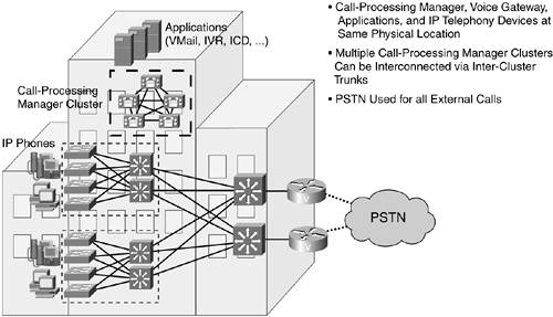

The past few years have seen a major shift in the development of VoIP protocols. This section is not intended as a full detailed description of all the developments because that could easily encompass an entire book by itself. Readers interested in understanding VoIP in its entirety should read Cisco Voice over Frame Relay, ATM, and IP (Cisco Press) for a comprehensive description of VoIP networks. Here we concentrate on giving a brief overview of the three protocols that are being deployed in most current VoIP solutions. These are H323, Media Gateway Control Protocol (MGCP), and Session Initiation Protocol (SIP).
H.323 is a standard created by the International Telecommunications Union (ITU). There currently exist four versions: v1 was approved in 1996, v2 in January 1998, v3 in September 1999, and v4 in November 2000. It provides specifications for real-time, interactive videoconferencing, data sharing, and audio applications such as IP telephony. The H.323 recommendations cover the IP devices that participate and control H.323 sessions and the elements that interact with the switched-circuit network. H.323 standards do not include the LAN itself, nor the transport layer that interconnects LAN segments. In common with other ITU multimedia teleconferencing standards, H.323 implementation applies to either point-to-point or -multipoint sessions. The H.323 recommendation allows multipoint conferences through a variety of methods and allows for either centralized or decentralized conference technologies.
In a general H.323 implementation, four logical entities or components are required:
Terminal—. A terminal, or a client, is an endpoint where H.323 data streams and signaling originate and terminate. It may be a multimedia PC with a H.323-compliant stack or a standalone device such as a universal serial bus (USB) IP telephone. A terminal must support audio communication; video and data communication support is optional.
Gateway—. A gateway is an optional component in an H.323-enabled network. When communication is required between different networks, however, a gateway is needed at the interface. Through the provision of gateways in H.323, it is possible for H.323 terminals to interoperate with other H.32x-compliant conferencing terminals. For example, it is possible for a H.323 terminal to set up a conference with terminals based on H.320 or H.324 through an appropriate gateway. A gateway provides data format translation, control signaling translation, audio and video codec translation, and call setup and termination functionality on both sides of the network. Depending on the type of network for which translation is required, a gateway may support H.310, H.320, H.321, H.322, or H.324 endpoints.
Multipoint control unit (MCU)—. The MCU is also an optional component of an H.323-enabled network. It enables conferencing between three or more endpoints and consists of a mandatory multipoint controller (MC) and zero or more multipoint processors (MP). Although the MCU is a separate logical unit it may be combined into a terminal, gateway, or gatekeeper. The multipoint controller provides a centralized location for multipoint call setup. Call and control signaling are routed through the MC so that endpoints capabilities can be determined and communication parameters negotiated. An MC may also be used in a point-to-point call, which can later be extended into a multipoint conference. Another useful job of the MC is to determine whether to unicast or multicast the audio and video streams depending on the capability of the underlying network and the topology of the multipoint conference. The multipoint processor handles the mixing, switching, and processing of the audio, video, and data streams among the conference endpoints.
The MCU is required in a centralized multipoint conference where each terminal establishes a point-to-point connection with the MCU. The MCU determines the capabilities of each terminal and sends each a mixed media stream. In the decentralized model of multipoint conferencing, an MC ensures communication compatibility but the media streams are multicast and the mixing is performed at each terminal.
Gatekeeper—. A gatekeeper is an optional component of an H.323-enabled network. Gatekeepers provide central management and control services and are needed to ensure reliable, commercially feasible communications. When a gatekeeper exists, all endpoints (terminals, gateways, and MCUs) must be registered with it. Registered endpoints' control messages are routed through the gatekeeper. The gatekeeper and the endpoints it administers form a management zone.
The services a gatekeeper provides to all endpoints in its zone include the following:
Address translation—. A gatekeeper maintains a database for translation between aliases, such as international phone numbers and network addresses.
Admission and access control of endpoints—. This control can be based on bandwidth availability, limitations on the number of simultaneous H.323 calls, or the registration privileges of endpoints.
Bandwidth management—. Network administrators can manage bandwidth by specifying limitations on the number of simultaneous calls and by limiting authorization of specific terminals to place calls at specified times.
Routing capability—. A gatekeeper can route all calls originating or terminating in its zone. This capability provides numerous advantages. First, accounting information of calls can be maintained for billing and security purposes. Second, a gatekeeper can reroute a call to an appropriate gateway based on bandwidth availability. Third, rerouting can be used to develop advanced services such as mobile addressing, call forwarding, and voice-mail diversion.
Terminals, gateways, and MCUs are collectively known as endpoints. Even though an H.323-enabled network can be established with only terminals, the other components are essential to provide greater practical usefulness of the services.
Actually a suite of protocols, H.323 incorporates many individual protocols that have been developed for specific applications. Figure 3-30 illustrates the relationships of these components in the protocol stack.

The following core components are part of H.323:
Control and signaling—. Control information is essential for call setup and tear down, capability exchange and negotiation, and administrative purposes. H.323 uses three control protocols: H.225 RAS, H.225/Q.931 call signaling, and H.245 media control.
H.225.0 RAS—. RAS (registration/authorization/status) messages define communications between endpoints and a gatekeeper. H.225.0 RAS is only needed when a gatekeeper exists. H.225.0 RAS uses unreliable transport for delivery, which in an IP network means using UDP.
H.225—. Specifies messages for call control, including signaling, registration and admissions, and packetization/synchronization of media streams. Call signaling is a basic requirement needed to set up and tear down a call between two endpoints. H.225.0 uses a subset of Q.931 signaling protocol for this purpose. Q.931 was initially developed for signaling in Integrated Services Digital Networks (ISDNs). H.225.0 adopts Q.931 signaling by incorporating it in its message format. H.225.0 call signaling is sent directly between the endpoints when no gatekeeper exists. When a gatekeeper exists, it may be routed through the gatekeeper.
H.245—. Specifies messages for opening and closing channels for media streams and other commands, requests, and indications. It allows endpoints to negotiate to determine compatible settings before audio, video, and/or data communication links can be established. H.245 is mandatory to implement in all endpoints.
Video codecs—. Recommendation H.323 specifies two video codecs: H.261 and H.263. However, H.323 clients are not limited to these codecs only. Other codecs can be used provided both terminals agree on and support it. Video support in H.323 terminals and MCUs is optional.
The H.261 codec is used for audiovisual services for channels with bandwidths p x 64 kbps, where p can range from 1 to 30. The H.263 codec is a specification for a new video codec for video basic telephone service and is designed for low-bit-rate transmission without loss of quality.
Audio codecs—. H.323 specifies a series of audio codecs ranging in bit rates from 5.3 to 64 kbps. The mandatory codec is G.711, which uses pulse code modulation to produce bit rates of 56 and 64 kbps. G.711 is a popular codec designed for telephone networks. However, it is less appropriate for communication over the Internet, where subscriber loop bandwidths are much smaller. Nowadays, most H.323 terminals support G.723.1, which is much more efficient and produces good quality audio at 5.3 kbps and 6.3 kbps. The G.728 and G.729 codecs use advanced linear prediction quantization of digital audio to produce high-quality audio at 16 kbps and 8 kbps, respectively. The following list summarizes the list of audio codecs:
G.711—. Audio codec, 3.1 kHz at 48, 56, and 64 kbps (normal telephony)
G.722—. Audio codec, 7 kHz at 48, 56, and 64 kbps
G.723—. Audio codec for 5.3- and 6.3-kbps modes
G.728—. Audio codec, 3.1 kHz at 16 kbps
G.729—. Audio codec
Real-time transport—. The Real-Time Transport Protocol (RTP) and the associated control protocol (Real-Time Control Protocol [RTCP]) are used for timely and orderly delivery of audio and video streams. RTP/RTCP is an IETF recommendation that provides logical framing, sequence numbering, time stamping, payload distinction (for instance, between audio and video and between different codecs), and source identification. It may also provide basic error detection and correction. Note that the RTP layer is above the transport layer of the underlying network.
The H.323 protocol stack runs on top of the transport and network IP layers. Reliable transport is for control signals and data, because signals must be received in proper order and cannot be lost. Unreliable transport is used for audio and video streams, which are time sensitive. Delayed audio and video packets are dropped. Consequently, TCP is applied to the H.245 control channel, the T.120 data channels, and the call-signaling channel, whereas UDP applies to audio, video, and registration/authorization/status (RAS) channels. Ports or sockets used for H.245 signaling, audio, video, or data channels are dynamically negotiated between endpoints.
Figure 3-31 shows an example of the H.232 call-signaling flows when a gatekeeper is used.

The RAS signaling protocol is used between terminals or gateways and gatekeepers. The RAS channel is opened before any other channel and is independent of the call setup and media transport channels. Initially, the terminals/gateway must discover their zone gatekeepers, which can be accomplished in two ways:
Unicast discovery—. This is a manual discovery method that uses UDP port 1718. Endpoints are configured with the gatekeeper IP address and can attempt to begin the registration process by sending gatekeeper request (GRQ) messages. The gatekeeper will reply with a gatekeeper reject (GRJ) message or a gatekeeper confirm (GCF) message, which contains the transport address of the gatekeeper RAS channel.
Multicast discovery—. This is an autodiscovery method that uses the UDP multicast address 224.0.1.41 and enables endpoints to discover its gatekeeper through a multicast message. A gatekeeper can be configured to respond only to certain subnets.
If a gatekeeper is not available, the gateway periodically attempts to rediscover a gatekeeper. When a gatekeeper is discovered, the registration process begins. Registration is the process by which gateways, terminals, and/or MCUs join a zone and inform the gatekeeper of their IP and alias addresses. Every gateway can register with only one active gatekeeper because there is only one active gatekeeper per zone. The H.323 gateway registers either with an H.323 ID (e-mail ID) or an E.164 address (telephone number). RAS uses UDP port 1719 for H.225 RAS messages.
The H.225 call control signaling is used to set up connections between H.323 endpoints using Q.931 signaling messages, which connect, maintain, and disconnect calls. The reliable call control channel is set up using TCP port 1720. When a gatekeeper does not exists, the H.225 messages are exchanged directly between the endpoints. When a gatekeeper is present, the H.225 call setup messages are exchanged either via direct call signaling or via gatekeeper-routed call signaling. The method chosen is decided by the gatekeeper during the RAS message exchange.
The H.245 protocol then establishes logical channels for transmission of audio, video, data, and control channel information. One H.245 session is established for each call. It negotiates channel usage, flow control, and capabilities exchange messages. This is accomplished through the use of dynamically allocated TCP ports.
NOTE
H.323v2 added a fast-connect capability that allows endpoints to establish a basic connection in as little as one round trip. It multiplexes H.245 logical channel proposals in an H.225 call-signaling channel. An endpoint may refuse fast connect and revert to normal H.245 procedures.
Finally, the RTP/RTCP sessions are established; these carry the voice or video data between the two ends. These sessions run over UPD using dynamically allocated UDP ports.
Figure 3-32 shows an example between gateways and gatekeeper interaction during an interzone call setup where two H.323 terminals are located in two different zones.

The steps that take place are as follows:
Terminal A dials the phone number for terminal B (831-334-1234).
Gateway A sends a RAS admission request (ARQ) to gatekeeper 1, asking permission to call terminal B.
Gatekeeper 1 does a lookup and does not find terminal B registered; it does a prefix lookup on the phone number and finds a match with gatekeeper 2; gatekeeper 1 sends a RAS location request (LRQ) message to gatekeeper 2 to get the IP address of terminal B; it also sends a RAS request-in-progress (RIP) message to gateway A.
Gatekeeper 2 does a lookup and finds terminal B registered; it returns a RAS location confirm message (LCF), which includes the IP address of gateway B.
Gatekeeper 1 returns a RAS admission confirm (ACF) message to terminal A, which contains the IP address of gateway B.
Gateway A sends a Q.931 call-setup message to gateway B with terminal B's phone number.
Gateway B sends gatekeeper 2 a RAS admission request (ARQ) asking permission to answer gateway A's call.
Gatekeeper 2 returns a RAS admission confirm (ACF) message, which contains the IP address of gateway A.
Gateway B sets up a POTS call to terminal B at 831-334-1234.
When terminal B answers, Gateway B sends a Q.931 connect message to gateway A.
This is then followed by the H.245 logical channel setup and RTP/RTCP data transfer.
The Media Gateway Control Protocol is another VoIP protocol standard and was designed for simplicity. In MGCP, media gateway controllers or call agents provide control, signaling, and the processing skills to control the telephony gateways. A telephony gateway is a network device that provides conversion between the audio signals carried on telephone circuits and data packets carried on packet networks. MGCP assumes a call-control architecture wherein the call-control “intelligence” is outside the gateways and is handled by external call-control elements. MGCP is a master/slave protocol, wherein the gateways execute the commands sent by the call agents. The call agent implements the signaling layers of H.323 (listed earlier in the H.323 section) and appears to H.323 devices as an H.323 gatekeeper or one or more H.323 endpoints.
It is possible to build an agent that accepts both H.323 and SIP call setup requests and then uses MGCP to establish calls between MGCP media gateways and H.323 and SIP gateways or endpoints. A basic MGCP-based telephony system involves one or more media gateways and at least one agent, sometimes called a media gateway controller. MGCP messages between the call agent and media gateway are sent via UDP/IP. The agent is signaled by all the media gateways that serve it of events such as incoming call, off-hook, and hang-up. The agent, in turn, sends commands to all of these media gateways to ring phones, dial numbers, and establish RTP/RTCP connections.
NOTE
MEGACO (Media Gateway Control)/H.248 is an emerging, incompatible next-generation protocol to MGCP. The IETF group that developed MGCP has joined forces with the ITU and developed MEGACO/H.248 that is standardized by both agencies. It is a master/slave, transaction-oriented protocol in which media gateway controllers (MGCs) control the operation of media gateways (MGs) . Most companies that are currently deploying MGCP products plan to move to MEGACO.
Session Initiation Protocol, defined in RFC 3261, is the principal IETF standard for multimedia conferencing over IP. It is an ASCII-encoded, application layer control protocol that can be used to establish, maintain, and terminate calls between two or more endpoints. Whereas the H.323 protocol uses a more traditional circuit-switched approach to signaling, the SIP protocol is a lightweight, text-based protocol that is based on the HTTP protocol. SIP is becoming the protocol of choice over MGCP due to its simplicity and inherent IP-based architecture. A feature in SIP that records the route traversed has been found to be extremely useful for billing and call-control purposes.
SIP is part of the IETF multimedia data and control architecture, which includes protocols such as the RTP for transporting real-time data and providing quality of service feedback, the Real-Time Streaming Protocol (RTSP) for controlling delivery of streaming media, MEGACO for controlling gateways to the PSTN, the Session Announcement Protocol (SAP), and the Session Description Protocol (SDP) for describing multimedia sessions. The functionality and operation of SIP does not depend on these protocols and it can be used with other call setup and signaling protocols.
SIP is designed to address the functions of signaling and session management within a packet telephony network. Signaling allows call information to be carried across network boundaries. Session management provides the ability to control the attributes of an end-to-end call.
SIP provides the capabilities to do the following:
Determine the location of the target endpoint—. SIP supports address resolution, name mapping, and call redirection.
Determine the media capabilities of the target endpoint—. Via Session Description Protocol (SDP), SIP determines the “lowest level” of common services between the endpoints. Conferences are established using only the media capabilities that can be supported by all endpoints.
Determine the availability of the target endpoint—. If a call cannot be completed because the target endpoint is unavailable, SIP determines whether the called party is already on the phone or did not answer in the allotted number of rings. It then returns a message indicating why the target endpoint was unavailable.
Establish a session between the originating and target endpoint—. If the call can be completed, SIP establishes a session between the endpoints. SIP also supports mid-call changes, such as the addition of another endpoint to the conference or the changing of a media characteristic or codec.
Handle the transfer and termination of calls—. SIP supports the transfer of calls from one endpoint to another. During a call transfer, SIP just establishes a session between the transferee and a new endpoint (specified by the transferring party) and terminates the session between the transferee and the transferring party. At the end of a call, SIP terminates the sessions between all parties.
SIP uses a client/server model, where the client initiates SIP requests and a server responds to the requests. A SIP architecture consists of user agent clients (UACs) and user agent servers (UASs). The UAC is the client application that initiates SIP requests, and the UAS is the server application that responds to a SIP request on behalf of the user. The SIP user agent applications contain both functionalities, that of the UAC and the UAS.
SIP clients include the following:
Phones—. Can act as either a UAC or UAS. Softphones (PCs that have phone capabilities installed) and SIP IP phones can initiate SIP requests and respond to requests.
Gateways—. Provide call control. Gateways provide many services, the most common being a translation function between SIP conferencing endpoints and other terminal types. This function includes translation between transmission formats and between communications procedures. In addition, the gateway translates between audio and video codecs and performs call setup and clearing on both the LAN side and the switched-circuit network side.
SIP servers include the following:
Proxy server—. The proxy server is an intermediate device that handles the routing of SIP messages. It receives SIP requests from a client and then forwards the requests on the client's behalf. Proxy servers can provide functions such as authentication, authorization, network access control, routing, reliable request retransmission, and security.
Redirect server—. Provides the client with information about the next hop or hops that a message should take so that the client can directly contact the next-hop server or user agent (UA).
Registrar server—. Processes requests from UAs for registration of their current location. Note that it does not route SIP messages but only handles registrations from SIP UAs. Registrar servers are often co-located with a redirect or proxy server.
Users in a SIP network are identified by unique SIP addresses, which are in the form of e-mail-like names such as [email protected] and are used as part of URLs in the format of sip:[email protected]. These are often referred to as SIP Uniform Resource Identifiers (URIs). The user ID can be either a username or an E.164 address. Users register with a registrar server using their assigned SIP addresses. The registrar server provides this information to the location server upon request.
There exist six main SIP signaling message types:
With the exception of the ACK message type, all requests trigger a response. The response messages contain a status code that indicates the result of the server's attempt to process a client's request. SIP response codes are extensible and SIP applications are not required to understand all codes as long as the class of the code is recognized. There are two types of status codes, provisional and final. Provisional codes (1xx) are for informational purposes and indicate that the server contacted is performing some further action and does not yet have a definitive response. A server sends a 1xx response if it expects to take more than 200 ms to obtain a final response. All other codes are final codes and represent a conclusion to the transaction. A nonfinal response code is always followed by a final code.
SIP messages may be unicast or multicast to their destination(s). When a user initiates a call, a SIP request is sent directly to the IP address of the server, or to a locally configured SIP proxy server.
Figure 3-33 shows an example of SIP UA-to-UA signaling without a server.
Three mandatory packets are required for the call-establishment handshake: INVITE, INVITE OK, and ACK. It is also common to send the status messages of TRYING (code=100) and RINGING (code=180). When the call recipient picks up the phone, an ACK message is sent, acknowledging the call. When the SIP signaling exchange is completed, the logical channel is set up via RTP/RTCP.
Figure 3-34 shows how SIP operates through use of a proxy server.
Upon initialization, and at periodic intervals, SIP phones send REGISTER messages to a SIP registrar server; these messages contain the addressing information of the phone. The registrar writes this association, also called a binding, to a database, called the location service, where the addressing information can be used by the proxy. Often, a registrar server for a domain is co-located with the SIP proxy server for that domain. It is an important concept that the distinction between types of SIP servers is logical, not physical.
A user is not limited to registering from a single device. For example, both a phone at home and the one in the office could send registrations. This information is stored together in the location service and allows a proxy to perform various types of searches to locate the user. Similarly, more than one user can be registered on a single device at the same time.
When the caller wants to place a call, the SIP phone initially may not know the location of the destination phone and therefore sends the initial INVITE request to the SIP proxy. The address of the proxy server could be manually configured in the SIP phone or it could have been discovered via DHCP.
In some cases, it may be useful for proxies in the SIP signaling path to see all the messaging between the endpoints for the duration of the session. This would require adding a routing header field known as Record-Route in the SIP messages, which would contain a URI resolving to the host name or IP address of any traversed proxy servers.
NOTE
In SIP, registration is used for routing incoming SIP requests and has no role in authorizing outgoing requests. Authorization and authentication are handled in SIP either on a request-by-request basis with a challenge/response mechanism, or by using a lower-layer scheme (as discussed in the “VoIP Security Protocol” section later in this chapter).
One other interaction is worth mentioning. SIP IP phones support dynamic content services via an HTTP client and Extensible Markup Language (XML) support. The IP phone contains a service locator that is responsible for contacting the call-process manager to determine what authorized services are available. When a service is accessed on the IP phone, it creates an HTTP connection to the proxy server. When the list of services is determined, the phone then creates another HTTP connection to the call-processing manager. In this connection request is included the phone's identification (MAC address). This allows the call-processing manager to check which services the phone has enabled and then notify the phone. At this point, the services available to the user display on the phone.
SIP and H.323 are competing protocols; however, both protocols can coexist in the same packet telephony network if a device that supports the interoperability is available. The H.323 protocol has been available for many years, and carriers have made significant investment in deploying large H.323-based networks. SIP is growing in popularity due to its capability to easily combine voice and IP-based services. It is expected that both will coexist in the years to come.
Cisco has developed a SIP proxy server that has added capabilities to communicate with an H.323 gatekeeper using the H.323 RAS protocol. The Cisco SIP proxy server acts as an H.323 gateway to the H.323 network. The SIP proxy-to-gateway communication is used only for call signaling and routing and not for any type of protocol translation. Figure 3-35 illustrates an example where a SIP phone establishes a call to an H.323 terminal.

The H.323 gateway and H.323 gatekeeper exchange registration request and registration confirm messages. When the SIP proxy receives an INVITE request from a SIP phone, it interacts with the H.323 gateway to establish a call setup between the H.323 gateway and the H.323 terminal using H.225. Note that this example uses the fast-connect capability to establish an H.245 logical channel. After the H.225 call setup has completed between the H.323 terminal and the H.323 gateway, the SIP proxy completes the call setup with the SIP phone. The RTP/RTCP logical media channels subsequently set up between the SIP phone and the H.323 terminal.
Many next-generation VoIP networks will use SIP as the foundation for VoIP deployment. However, because many existing VoIP deployments use H.323, it is expected that SIP and H.323 will co-exist in many environments. As such, this discussion mostly focuses on how to secure H.323 and SIP-based VoIP networks.
The ITU-T recommendation H.235 defines security and encryption for H.232 and H.245 multimedia terminals. It includes the capability to negotiate services and functionality in a generic manner, and to be selective concerning cryptographic techniques and capabilities used. There are no specifically mandated algorithms; however, it is strongly suggested that endpoints support as many of the applicable algorithms as possible to achieve interoperability.
The RAS channel used for gateway-to-gatekeeper signaling is not a secure channel. To ensure secure communication, H.235 allows gateways to include an authentication key in their RAS messages. Two types of authentication mechanisms can be used:
Symmetric encryption-based authentication—. This method uses public key cryptography and a Diffie-Hellman exchange to obtain a shared secret and requires no prior contact between the endpoint and gatekeeper. At the end of the Diffie-Hellman exchange, both the entities possess a shared secret key along with a chosen algorithm with which to use this key. This shared secret key can then be used on any subsequent request/response exchanges. Typically, the authentication is performed by encrypting the gatekeeper ID using a combination of the negotiated shared secret and the XOR function.
If the messages are exchanged over an insecure channel, digital signatures (or other message origin authentication method) must be used to authenticate the parties between whom the secret will be shared.
Subscription-based authentication—. This authentication exchange assumes that each end possesses some well-known identifier (such as a text identifier) that uniquely identifies it. A mutual two-pass authentication is defined which may be performed only in one direction when the messages originating from the reverse direction do not need to be authenticated. A three-pass authentication procedure uses a randomly generated, unpredictable challenge number as a challenge from the authenticator. Different from the two-pass procedure, the three-pass procedure does not authenticate the first, initial message holding the initiator's challenge.
All RAS messages contain the authentication tokens required by the specific mode of operation. Three different variations may be implemented:
Password-based with symmetric encryption
Password-based with hashing
Certificate-based with signatures
The intent behind the certificate-based exchange is to authenticate the user of the endpoint, not just the physical endpoint. Using digital certificates, an authentication protocol proves that the respondents possess the private keys corresponding to the public keys contained in the certificates. For authentication using public key certificates, the endpoints are required to provide digital signatures using the associated private key value.
NOTE
The passwords configured on the H.323 endpoint and gateway authenticate the devices. In addition, many vendors are implementing per-call authentication where specific users are also authenticated. When the gateway receives a call, it prompts the user for a user ID and personal identification number (PIN). These two numbers are included in certain RAS messages sent from the endpoint and are used to authenticate the originator of the call.
The call setup channel operates in the negotiated secured or unsecured mode starting with the first exchange. Because the H.225.0 messages are the first exchanged when establishing H.323 communications, there can be no security negotiations “in band” for H.225, and both parties must know a priori that they are using a particular security mode. For H.225 call setup, the TCP port 1300 is used for TLS secured communications.
One purpose of the H.225 exchanges as they relate to H.323 security is to provide a mechanism to set up the secure H.245 channel. The signaling to use TLS, Ipsec, or a proprietary mechanism on the H.245 control channel is done on the secured or unsecured H.225.0 channel during the initial Q.931 message exchange. Optionally, authentication may occur during the exchange of H.225 messages. This authentication may be certificate- or password- based, using encryption and/or hashing (that is, signing) in the same manner as discussed previously for RAS authentication.
The H.245 channel can be secured using any negotiated privacy mechanism. (This includes the option of “none.”) The only requirement on all systems is that each shall have some manner in which to negotiate and/or signal that the H.245 channel is to be operated in a particular secured manner before it is actually initiated. H.323 will use the H.225.0 connection signaling messages to accomplish this.
Endpoints exchange capabilities using H.245 messages. These capability sets can contain definitions that indicate security and encryption parameters, including encryption algorithms and keys. The capability to do this, on a logical channel by logical channel basis, allows different media channels to be encrypted by different mechanisms. Each encryption algorithm that is used in conjunction with a particular media codec implies a new capability definition.
Assuming that the connection procedures indicate a secure mode of operation, the negotiated handshake and authentication shall occur for the H.245 logical channel before any other H.245 messages are exchanged. After completing the securing of the H.245 channel, the terminals use the H.245 protocol in the same manner that they would in an insecure mode.
Alternatively, the H.245 channel may operate in an unsecured manner and the two entities open a secure logical channel with which to perform authentication and/or shared-secret derivation. For example TLS or IPsec may be used by opening a logical channel that could then be used to derive a shared secret that protects any media session keys.
An encrypted H.245 control channel can be used to establish cryptographic keying material and/or set up the logical channels that will carry the encrypted media streams. The H.245 secure channel may be operated with characteristics different from those in the private media channel(s) as long as it provides a mutually acceptable level of privacy. This allows for the security mechanisms protecting media streams and any control channels to operate in a completely independent manner, providing completely different levels of strength and complexity.
If it is required that the H.245 channel be operated in a nonencrypted manner, the specific media encryption keys may be encrypted separately in the manner signaled and agreed to by the participating parties. A separate secure logical channel may be created to accomplish this, using either TLS or IPsec.
The encryption key may be protected by using one of the three possible mechanisms as they are passed between two endpoints.
If the H.245 channel is secure, no additional protection is applied to the key material.
If a secret key and algorithm has been established outside the H.245 channel, the shared secret is used to encrypt the key material.
Certificates may be used when the H.245 channel is not secure, but may also be used in addition to the secure H.245 channel. When certificates are used, the key material is encrypted using the certificate's public key.
RTP streams are encrypted on a packet-by-packet basis. Transport-specific header information is not encrypted (the RTP header as well as the payload header), and the privacy of data is based upon end-to-end encryption.
Whether or not the RTP packets are encrypted, a lightweight packet authentication mechanism is defined, which ensures packet integrity through the use of a message authentication code (MAC). This is referred to as the anti-spam method in the H.235 specification. The MAC is computed on selected fields in the RTP header. It is recommended to use the key that is obtained from the H.245 media session key distribution (even if the session key applied is not used for payload encryption).
Synchronization of new keys and encrypted text is based upon a dynamic payload type. The initial encryption key is presented by the sender in conjunction with the dynamic payload number. The receiver(s) of the media stream will start using the key upon receipt of this payload number in the RTP header. New key(s) may be distributed at any time by the sending endpoint. The synchronization of the newer key with the media stream shall be indicated by the changing of the payload type to a new dynamic value. Note that the specific values do not matter, as long as they change for every new key that is distributed.
The fundamental network-security services required for SIP are preserving the confidentiality and integrity of messaging, preventing replay attacks or message spoofing, providing for the authentication and privacy of the participants in a session, and preventing denial-of-service attacks.
Instead of defining new security mechanisms specific to SIP, SIP reuses existing security models derived from the HTTP and SMTP space. The SIP protocol does not define a specific encryption or authentication technique that must be used with SIP implementations. However, it does specify how HTTP authentication and S/MIME can be used with SIP and also allows for other techniques to be used.
NOTE
Because HTTP basic authentication uses passwords that are sent in the clear and is inherently insecure, this form of authentication has been deprecated in the current SIP standard. Similarly, the Pretty Good Privacy (PGP) mechanism for encrypting the header fields and bodies of SIP messages described in RFC 2543 has been deprecated.
SIP entities have a need to identify one another in a secure fashion. The authentication can take place between the UA and the proxy, where the proxy server requires a UA to authenticate itself before proceeding to process an INVITE message from it. Similarly, a UA can request authentication of a proxy or redirect server. A cryptographic authentication mechanism based on HTTP's digest authentication technique is provided in SIP to address this requirement.
The HTTP digest authentication technique requires a shared secret between the client and the server and is based on a cryptographic hash that includes the username, password, and a challenge provided by the server. The challenge provided by the server is called a nonce and is implementation-dependent; the selection and usage of this parameter determines the security of the digest authentication. The nonce should include a server-specific key, a time stamp, the client IP address, and some cryptographically random data to ensure maximum security.
SIP relies on specific response codes as well as specific header fields for carrying challenges and credentials. The authorization header contains a signature computed across components of the SIP message. This header does not change in transit between proxies and consists of the nonce, the realm, the request method (the type of request message sent by a user agent client), the request method version, and the authorization type. There is also a proxy-authorization header, which is used by a SIP UA to identify itself to a proxy. This contains the type of authentication, credentials of the UA, and/or realm of the resource being requested.
When authentication is achieved, it must be determined whether the authenticated entity is authorized to use the services it is requesting. Despite being securely authenticated, a party may not have permission to use all or some of the services that are being requested, and may require further authorization. This is typically accomplished using RADIUS.
Some extensions to RADIUS have been made to support the HTTP digest authentication so that it can be used with SIP. The UAs authenticate themselves with the proxy by using the HTTP digest authorization header. The proxy, acting as a RADIUS client, sends the username, nonce, and other information required to compute the digest authentication hash value, except the password, along with the hash to the RADIUS server. The server retrieves the password from its database and computes the hash from the password and other values it received. If the computed hash matches the received hash, the client can be authorized.
NOTE
Where a single request URI from a user agent is destined for multiple recipients, the message is forked: The SIP proxy receives a single message from the originating user agent and replicates it to each correspondent destination, having labeled each one with a unique ID. Assuming the recipients are contactable, each responds to the proxy with a SIP message containing a challenge. However, this causes an authentication problem. The proxy forwards on to the user agent only the first challenge response it receives. Subsequent challenges arriving at the proxy from the other destinations are ignored. Therefore, only the first destination to respond is authorized to participate in the SIP-initiated session and the calls to the other destinations are dropped. Because of this, multiple recipients and authorization are currently incompatible.
An independent security mechanism for SIP message bodies supplies an alternative means of end-to-end mutual authentication and provides a limit on the degree to which UAs must trust intermediaries.
SIP messages carry MIME bodies, and the MIME standard includes mechanisms for securing MIME contents to ensure both integrity and confidentiality. Encrypting entire SIP messages end to end for the purpose of confidentiality is not always appropriate because network intermediaries (such as proxy servers) need to view certain header fields in order to route messages correctly; and if these intermediaries are excluded from security associations, SIP messages will essentially be nonroutable. However, S/MIME allows SIP UAs to encrypt MIME bodies within SIP, securing these bodies end to end without affecting message headers. S/MIME can provide end to end confidentiality and integrity for message bodies, as well as mutual authentication. It is also possible to use S/MIME to provide a form of integrity and confidentiality for SIP header fields through SIP message tunneling.
Full encryption of messages provides the best means to preserve the confidentiality of signaling—it can also guarantee that messages are not modified by any malicious intermediaries. However, SIP requests and responses cannot be naively encrypted end-to-end in their entirety because some message fields need to be visible to proxies in most network architectures so that SIP requests are routed correctly. Note that proxy servers need to modify some features of messages as well for SIP to function. Proxy servers must therefore be trusted, to some degree, by SIP UAs. To this purpose, transport and/or network layer security mechanisms for SIP are recommended, which encrypt the entire SIP requests or responses on the wire on a hop-by-hop basis, and that allow endpoints to verify the identity of proxy servers to whom they send requests.
SIP offers various security mechanisms for hop-by-hop and end-to-end encryption of certain sensitive header fields and the message body. Hop-by-hop encryption is needed in instances where proxies need to access the field in the header that allows it to determine how to route a message. For example, a proxy must add itself to the Via field; however, it may first encrypt the rest of the Via fields to hide the previous part of the route. On the return path, the proxy can decrypt the information that it encrypted and pass the rest of the message along. In this manner, each hop only knows about the source and destination of that hop and not the rest of the route.
Transport or network layer security can encrypt SIP signaling traffic, guaranteeing message confidentiality and integrity. Often, certificates are used in the protocols that establish transport or network layer security. These certificates can be used to provide a means of authentication for SIP devices and users. Two popular alternatives for providing security at the transport and network layer are, respectively, TLS and IPsec.
TLS provides transport layer security over connection-oriented protocols and can be specified as the desired transport protocol for SIP. TLS is most suited to architectures in which hop-by-hop security is required between hosts with no preexisting trust association. For example, Teri trusts her local proxy server, which after a certificate exchange decides to trust Stuart's local proxy server, which Stuart trusts, hence Stuart and Teri can communicate securely.
TLS must be tightly coupled with a SIP application. Note that transport mechanisms are specified on a hop-by-hop basis in SIP; therefore, a UA that sends requests over TLS to a proxy server has no assurance that TLS will be used end-to-end.
The SIP specifications require that TLS implementations support the AES cipher algorithm with 128-bit keys and recommends implementing 3DES with 112-bit keys. SHA is the specified hash algorithm to use for authentication and integrity protection. TLS defers client authentication to something that is widely deployed (for instance, RADIUS).
IPsec is a set of network layer protocols that collectively can be used to secure IP traffic. It is most commonly used in architectures in which a set of hosts or administrative domains have an existing trust relationship with one another. As mentioned earlier in this chapter, IPsec creates secure tunnels through untrusted networks. Sites connected by these tunnels form VPNs. VoIP networks can be deployed as VPNs such that security associations can be established between two VoIP entities. Therefore, VoIP traffic flowing across different network components on a shared network can be protected and secured as if it were on a private network.
In many architectures IPsec does not require integration with SIP applications; IPsec is perhaps best suited to deployments in which adding security directly to SIP hosts would be arduous and where UAs already have a preshared keying relationship with their first-hop proxy server. Any deployment of IPsec for SIP would require an IPsec profile that uses traffic selectors specifically designed for SIP.
Many SIP proxy servers support authentication and authorization; IPsec and can be configured to provide authentication either at an external authentication server (for instance, RADIUS) or at the proxy itself. RADIUS functions by exchanging attribute value pairs (AV pairs) between the client and the server. For example, a SIP proxy server acting as a RADIUS client exchanges AV pairs with a RADIUS server to provide authentication functions.
The proxy may support different types of authentication mechanisms in conjunction with the appropriate RADIUS server, such as CHAP and HTTP digest authentication.
NOTE
The IETF Audio/Video Working Group is developing the Secure Real-Time Transport Protocol (sRTP), which is a security profile for RTP that provides confidentiality to RTP data and message authentication to RTP data and headers. It has gained some acceptance and seems to be the up-and-coming encryption scheme for VoIP. One very important reason is that it will support compression and encryption over lower-bandwidth links, which is something IPsec cannot do.
Deployment of security solutions in VoIP networks is still evolving because the standards to provide security services are fairly new and vendors are still working on providing comprehensive security mechanisms.
For H.323 networks, crypto tokens are generally used in a “password-with-hashing“ scheme to authenticate RAS gateway-to-gatekeeper signaling. The gateway will include an authentication key (crypto token) in its RAS message to the gatekeeper. This key is used by the gatekeeper to authenticate the source of the messages, typically by using a RADIUS server and a CHAP challenge containing the crypto token. The crypto tokens are validated by the RADIUS server using the password configured for the gateway. This is shown in Figure 3-36.
In addition, per-call authentication is generally available. In this case, the user is prompted for a user ID and PIN, which are the items used to authenticate the originator of the call. Both items are included in the RAS messages that are used to initiate a call, namely the admission request (ARQ) and admission confirm (ACF) messages. These messages are sent between the H.323 endpoint and the gateway. When used in conjunction with a gateway crypto token as described previously, all signaling messages provide origin authentication and sender validation.
A complete end-to-end signaling security solution is shown in Figure 3-37. All signaling messages are authenticated, and TLS is used to provide a secure H.225 call setup and H.245 call-control channel.

Note that the strength of this authentication, if passwords are used, depends largely on the secrecy of the passwords. Because the gateway-to-gatekeeper passwords are stored on critical infrastructure devices, these passwords should be relatively secure. If a AAA server such as RADIUS is used, the management of these passwords can be greatly simplified. For large enterprise networks looking to deploy a PKI, the use of digital certificates for authentication may be warranted.
For SIP-based VoIP networks, end-to-end security can be obtained as follows:
UAs authenticate themselves to servers (proxy servers, redirect servers, and registrars) with a digest username and password. Alternatively, TLS can be used, which supports a number of user-based legacy authentication mechanisms.
Servers authenticate themselves to UAs one hop away, or to another server one hop away (and vice versa), with a site certificate delivered by TLS.
For SIP implementations running over TCP, TLS or IPsec can be used for confidentiality. All UA-to-server communication runs over TCP.
For SIP implementations running over UDP, only IPsec can be used for confidentiality. (TLS only runs over TCP.) All UA-to-UA communication runs over UDP.
On a peer-to-peer level, UAs trust the network to authenticate one another; however, S/MIME can also be used to provide direct authentication when the network does not, or if the network itself is not trusted.
There is still ongoing work in the SIP working group of the IETF to resolve issues to effectively secure SIP-based voice traffic over any corporate network infrastructure. NAT environments create a large complication because VoIP traffic embeds IP addresses in the application layer and any mechanism that uses cryptographic means for message integrity and confidentiality will generally be ineffective in NAT environments. Performing encryption/decryption on a hop-by-hop basis is also not a scalable solution due to voice traffic latency considerations. At this time, any capabilities from vendors to secure VoIP traffic should be used and upcoming features and functionalities should be tracked.
This chapter discussed specific networking scenarios and the protocols that are available to provide effective security services. The networking scenarios included VPNs, wireless networks, and VoIP networks. Virtual private networks have the most robust security solutions because these types of networks have been deployed for a number of years and have gone through their growing pains. Wireless networks and VoIP networks are all still evolving as far as security is concerned. Standards are in the process of being defined to provide comprehensive, scalable security solutions. In some cases, vendors are implementing proprietary security capabilities to address current market needs until standard interoperable solutions are ratified.