
Today, there is an ever-growing dependency on computer networks for business transactions. With the free flow of information and the high availability of many resources, managers of enterprise networks have to understand all the possible threats to their networks. These threats take many forms, but all result in loss of privacy to some degree and possibly malicious destruction of information or resources that can lead to large monetary losses.
Knowing which areas of the network are more susceptible to network intruders and who is the common attacker is useful. The common trend in the past has been to trust users internal to the corporate network and to distrust connections originating from the Internet or from remote access networks using virtual private networks (VPNs), dial-in modems, and Integrated Services Digital Network (ISDN) lines. It is important to place trust in the employees internal to the network and in authorized people trying to use internal network resources from outside the corporation. However, trust must also be weighed with reality. According to some sources, at least 60 percent or more attacks are perpretrated by corporate insiders, and there is an increasing trend not to trust internal users and have stricter security measures in place. Wireless networks are becoming in more wide-spread use, and more stringent security considerations are often required in these instances. Restricted use of network infrastructure equipment and critical resources is necessary. Limiting network access to only those who require access is a smart way to deter many threats that breach computer network security.
Not all threats are intended to be malicious, but they can exhibit the same behavior and can cause as much harm—whether intended or not. Unfortunately, many networking infrastructures have to deal with the increasing issue of viruses and malware that can be found on compromised computing resources and pose unintentional security threats from unsuspecting employees. It is important to understand what types of attacks and vulnerabilities are common and what you can do at a policy level to guarantee some degree of safe networking.
This book does not address the many common host application vulnerabilities in detail; instead, it is more concerned with securing the networking infrastructure. In discussions of areas in which host vulnerabilities can be deterred or constrained in the network infrastructure, more details are given.
Many different types of threats exist, but many threats fall into three basic categories:
Unauthorized access
Impersonation
Denial of service
Unauthorized access is when an unauthorized entity gains access to an asset and has the possibility to tamper with that asset. Gaining access is usually the result of intercepting some information in transit over an insecure channel or exploiting an inherent weakness in a technology or a product.
Getting access to corporate network resources is usually accomplished by doing some reconnaissance work. Most likely, the corporate network will be accessed through the Internet, tapping into the physical wire, remote modem dial-in access, or wireless network access. Also, a very common component to reconnaissance work is social engineering of information, which is discussed later in this chapter in the section “Social Engineering.”
If an intruder is trying to gain unauthorized access via the Internet, he must do some information-gathering work to first figure out which networks or resources are susceptible to vulnerabilities. Some common methods used to identify potential targets follow.
A reachability check uses tools that verify that a given network or device exists and is reachable. For example, DNS queries can reveal such information as who owns a particular domain and what addresses have been assigned to that domain. This can then be followed by the ping command, which is an easy way to verify whether a potential target is reachable.
Other network utilities can also locate a reachable target, such as Finger, Whois, Telnet, and NSLOOKUP.
When live systems are discovered, an attacker will usually attempt to discover which services are available for exploitation. This is accomplished by a technique commonly known as port scanning. The sections in this chapter titled “The TCP/IP Protocol” and “The UDP Protocol” respectively detail both the TCP and UDP protocol and clarify how ports are used; suffice to say, however, that every application has a specific port number associated with it that identifies that application. Through the use of port scanners, intruders can gain access to information on which applications and network services are available to be exploited.
Figure 5-1 shows an example of a reconnaissance attempt.
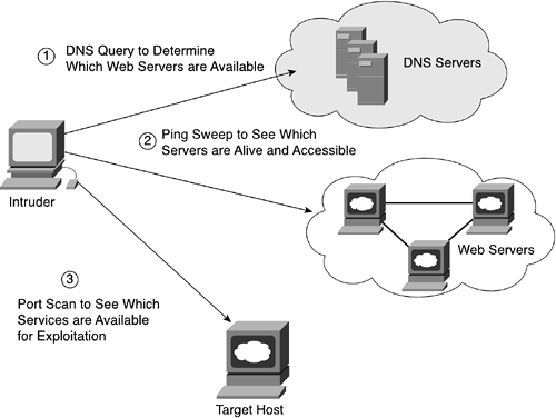
The intruder may follow these steps to gain unauthorized access to a web server:
DNS query to figure out which web servers are available.
Ping sweep to see which servers are alive and accessible.
Port scan to see which services are available for exploitation.
NOTE
Network reconnaissance cannot be prevented entirely. If Internet Control Message Protocol (ICMP) echo and echo-reply is turned off on edge routers, ping sweeps can be stopped, but at the expense of network diagnostic data. However, port scans can easily be run without full ping sweeps; they just take longer because they need to scan IP addresses that might not be live. Intrusion detection systems (IDSs) at the network and host levels can usually notify an administrator when a reconnaissance attack is underway. This enables the administrator to better prepare for the coming attack or to notify the Internet service provider (ISP) that is hosting the system that is launching the reconnaissance probe.
The ease or difficulty of packet snooping (also known as eavesdropping) on networks depends largely on the technology implemented. Shared media networks are particularly susceptible to eavesdropping because this type of network transmits packets everywhere along the network as they travel from the origin to the final destination. When concentrators or hubs are used in a shared media environment (such as FDDI, 10BASE-T, or 100-Mbps Ethernet), it can be fairly easy to insert a new node with packet-capturing capability and then snoop the traffic on the network. As shown in Figure 5-2, an intruder can tap into an Ethernet switch and, using a packet-decoding program, such as EtherPeek or TCPDump, read the data crossing the Ethernet.

In this example, the intruder gains access to username/password information and sensitive routing protocol data using an Ethernet packet decoder such as EtherPeek. The data packets being sent are captured by the laptop running EtherPeek; the program decodes the hex data into human-readable form. After obtaining access to information, the intruder can use this information to gain access to a machine and then possibly copy-restricted, private information and programs. The intruder may also subsequently have the capability to tamper with an asset; that is, the intruder may modify records on a server or change the content of the routing information.
In recent years, it has been getting much easier for anyone with a portable laptop to acquire software that can capture data crossing data networks. Many vendors have created user-friendly (read easy-to-use) packet decoders that can be installed with minimal cost. These decoders were intended for troubleshooting purposes but can easily become tools for malicious intent.
Packet snooping by using these decoding programs has another effect: The technique can be used in impersonation attacks, which are discussed in the next section.
Packet snooping can be detected in certain instances, but it usually occurs without anyone knowing. For packet snooping to occur, a device must be inserted between the sending and receiving machines. This task is more difficult with point-to-point technologies such as serial line connections, but it can be fairly easy with shared media environments. If hubs or concentrators are used, it can be relatively easy to insert a new node. However, some devices are coming out with features that remember MAC addresses and can detect whether a new node is on the network. This feature can aid the network manager in noticing whether any suspicious devices have been added to the internal network. In addition, using 802.1x, which is discussed in Chapter 2, “Security Technologies,” can provide an effective security measure against MAC address spoofing.
Figure 5-3 shows an example of a switch that has the capability to learn MAC addresses and provide some measure of port security. The 10BASE-T Ethernet switch provides connectivity to several hosts. The switch learns the source MAC addresses of the connecting hosts and keeps an internal table representing the MAC address and associated ports. When a port receives a packet, the switch compares the source address of that packet to the source address learned by the port. When a source address change occurs, a notification is sent to a management station, and the port may be automatically disabled until the conflict is resolved.

As surprising as it sounds, there are still people out there who use well-known exploits, such as war dialing, to gain unauthorized access. This term became popular with the film War Games and refers to a technique that involves the exploitation of an organization's telephone, dial, and private branch exchange (PBX) systems to penetrate internal network and computing resources. All the attacker has to do is find a user within the organization with an open connection through a modem unknown to the IT staff or a modem that has minimal or, at worst, no security services enabled. It is important to note that all unknown modems bypass any IT security measures—firewalls, virus checkers, authentication servers, and so on—and the use of unauthorized modems should be considered a severe security breach.
Many corporations still set up modems to auto-answer and will allow unauthenticated access from the Public Switched Telephone Network (PSTN) directly into your protected infrastructure. Many war-dialer programs are freely available on the Internet (for example, Modemscan, PhoneTag, ToneLoc, and so on), which greatly simplify the attack methodology and decrease the time required for the discovery of a vulnerability. Most programs automatically dial a defined range of phone numbers and log and enter into a database those numbers that successfully connect to the modem. Some programs can also identify the particular modem manufacturer and, if the modem is attached to a computer, can identify the operating system and may also conduct automated penetration testing. In such cases, the war dialer runs through a predetermined list of common usernames and passwords in an attempt to gain access to the system. If the program does not provide automated penetration testing, the intruder may attempt to break into a modem with unprotected logins or easily cracked passwords. Figure 5-4 illustrates a typical war-dialing scenario.

The steps to gain unauthorized access in a war-dialing scenario are as follows:
The intruder chooses a target and finds a list of phone numbers associated with this target. Phone numbers are easy to obtain via your handy phone book or even through corporate web pages.
The intruder uses the target's phone number block (usually a group of sequential numbers) and initiates the war-dialer application.
When the war-dialer application finishes, the intruder accesses the answered numbers from either a log file or database kept by the war-dialer application.
The intruder then tries to dial up and connect to the devices that answered. This is usually done via a deceptive path that hides the intruder's actual location.
Assuming the modem is set to auto-answer and has minimal password protection (if any), the intruder now has unauthorized access into the corporate network.
An interesting paper was presented in spring 2001 by Peter Shipley and Simson Garfinkel. Refer to http://www.dis.org/filez/WardialShipleyGarfinkel.pdf. This paper formally presents the results of the first large-scale survey of dialup modems. The survey dialed approximately 5.7 million telephone numbers in the 510, 415, 408, 650, and parts of the 707 area codes, and the subsequent analysis of the 46,192 responding modems that were detected.
NOTE
To mitigate this threat, war dialers, also sometimes referred to as modem scanners, should be used by system administrators to identify unauthorized and insecure modems deployed in an enterprise network. Also, an effective method to block war-dialing attacks is to use phone numbers in a range completely different from the corporation's internal PBX numbers. Make sure to keep these numbers secret and limit access to vital staff members.
Wireless networks are especially susceptible to unauthorized access. Wireless access points are being widely deployed in corporate LANs because they easily extend connectivity to corporate users without the time and expense of installing wiring. These wireless access points (APs) act as bridges and extend the network up to 300 yards. Many airports, hotels, and even coffee shops make wireless access available for free, and therefore most anyone with a wirelss card on his mobile device is an authorized user. However, many wireless networks only want to allow restricted access and may not be aware of how easily someone can gain access to these networks. (I know of quite a few instances where people have made it a sport to drive around their neighborhoods to see how many networks they can access.) The number of wireless networks that have zero security measures enabled is astounding. A majority of people run their APs in effectively open mode, which means they are basically wide open and have no encryption enabled. A majority also run in default Service Set Identifier (SSID) and IP ranges, which strongly implies that they've used little or no configuration when they set up their wireless LAN.
Chapter 3, “Applying Security Technologies to Real Networks,” extensively discusses wireless networks and how security technologies apply. Remember from that discussion that the 802.11 cards and access points on the market implement a wireless encryption standard, called the Wired Equivalent Protocol (WEP), which in theory makes it difficult to access someone's wireless network without authorization, or to passively eavesdrop on communications. However, WEP has many inherent weaknesses that enable intruders to crack the crypto with sophisticated software, and ordinary off-the-shelf equipment. Later in this chapter, vulnerabilities in wireless networks are discussed in more detail. Follow the developments in this area carefully so that as better security functionality becomes available—such as implementations for Temporal Key Integrity Protocol (TKIP), Light Extensible Authentication Protocol (LEAP), Protected Extensible Authentication Protocol (PEAP), and so on—you can deploy it. For now, it still makes sense to enable WEP and to ensure that all defaults have been changed so that some reasonable authentication and confidentiality services are being used. This will go a long way in reducing unauthorized access from just the random drive-by intruder.
Figure 5-5 shows an example of an intruder gaining access to a wireless network.

No matter which method is used for initial unauthorized access—reconnaisance work, access through the Internet, tapping into the physical wire, remote modem dial-in access, or wireless network access—the best way to deter unauthorized access is by using confidentiality and integrity security services to ensure that traffic crossing the insecure channel is scrambled and that it cannot be modified during transit.
Table 5-1 lists some of the more common access breaches and how they are a threat to corporate networks.
Table 5-1. Common Unauthorized Access Scenarios
Impersonation is closely related to unauthorized access but is significant enough to be discussed separately. Impersonation is the ability to present credentials as if you are something or someone you are not. These attacks can take several forms: stealing a private key or recording an authorization sequence to replay at a later time. These attacks are commonly referred to as man-in-the-middle attacks, where an intruder is able to intercept traffic and can as a result hijack an existing session, alter the transmitted data, or inject bogus traffic into the network. In large corporate networks, impersonation can be devastating because it bypasses the trust relationships created for structured authorized access.
Impersonation can come about from packet spoofing and replay attacks. Spoofing attacks involve providing false information about a principal's identity to obtain unauthorized access to systems and their services. A replay attack can be a kind of spoofing attack because messages are recorded and later sent again, usually to exploit flaws in authentication schemes. Both spoofing and replay attacks are usually a result of information gained from eavesdropping. Many packet-snooping programs also have packet-generating capabilities that can capture data packets and then later replay them.
Impersonation of individuals is common. Most of these scenarios pertain to gaining access to authentication sequences and then using this information to obtain unauthorized access. Once the access is obtained, the damage created depends on the intruder's motives. If you're lucky, the intruder is just a curious individual roaming about cyberspace. However, most of us will not be that lucky and will find our confidential information compromised and possibly damaged.
With the aid of cryptographic authentication mechanisms, impersonation attacks can be prevented. An added benefit of these authentication mechanisms is that, in some cases, nonrepudiation is also achieved. A user participating in an electronic communication exchange cannot later falsely deny having sent a message. This verification is critical for situations involving electronic financial transactions or electronic contractual agreements because these are the areas in which people most often try to deny involvement in illegal practices.
Impersonation of devices is largely an issue of sending data packets that are believed to be valid but that may have been spoofed. Typically, this attack causes unwanted behavior in the network. The example in Figure 5-6 shows how the unexpected modified behavior changes the routing information. By impersonating a router and sending modified routing information, an impostor was able to gain better connectivity for a certain user.
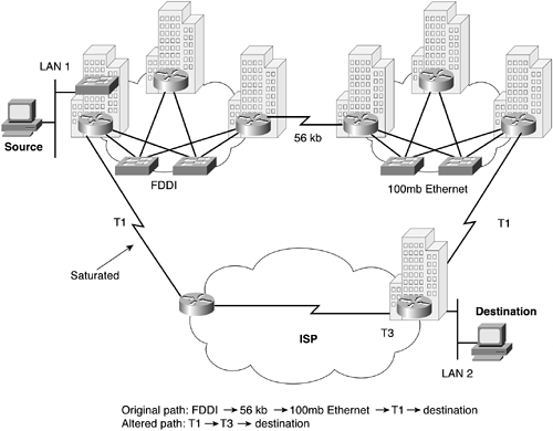
In this example, the intruder was connected to a corporate LAN and did a lot of work with another researcher on a different LAN. The backbone was set up in such a way that it took five hops and a 56-kbps line to get to the other research machines. By capturing routing information and having enough knowledge to change the routing metric information, the intruder altered the path so that his access became seemingly better through a backdoor connection. However, this modification resulted in all traffic from the intruder's LAN being rerouted, saturating the backdoor link, and causing much of the traffic to be dropped.
This is an extreme and premeditated example of impersonation. However, impersonation can also occur as an accident through unknown protocol and software behavior. For example, old versions of some operating systems have the innocuous behavior of acting as routers if more than one interface is connected; the OS sends out RIP (Routing Information Protocol) updates pointing to itself as the default. Figure 5-7 shows an example of this behavior.
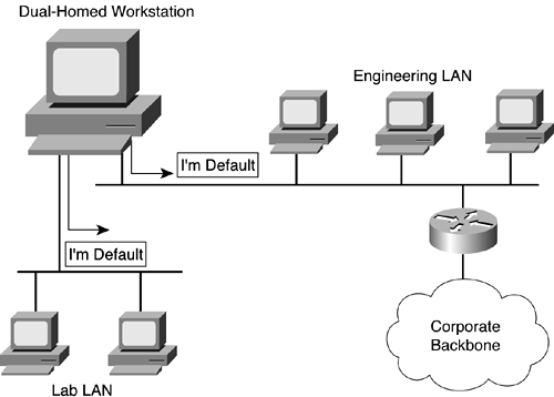
The routed network running RIP is set up to source a default RIP advertisement to all the hosts connected to the engineering lab's LAN. Hosts running RIP typically send all traffic destined to other IP subnets to the default router. If one of the workstations connected to this LAN has a second interface connected to another LAN segment, it advertises itself as the default router. This would cause all hosts on the engineering LAN to send traffic destined to other IP subnets to the misguided workstation. It can also cause many wasted hours troubleshooting routing behavior that can be avoided through the use of route authentication or the configuration of trusted sources for accepting routing updates. In the network infrastructure, you have to protect yourself from malicious impersonations and accidental ones.
NOTE
Many current networks use the Dynamic Host Configuration Protocol (DHCP), which provides a host with an IP address and an explicit default router. RIP is not used in these environments.
Impersonations of programs in a network infrastructure can pertain to wrong images or configurations being downloaded onto a network infrastructure device (such as a switch, router, or firewall) and, therefore, running unauthorized features and configurations. Many large corporate networks rely on storing configurations on a secure machine and making changes on that machine before downloading the new configuration to the device. If the secure machine is compromised, and modifications are made to device access passwords, downloading this altered configuration to a router, switch, or firewall results in an intruder being able to present false credentials—the modified password—and thereby gain access to critical network infrastructure equipment.
Impersonation can be deterred to some degree by using authentication and integrity security services such as digital signatures. A digital signature confirms the identity of the sender and the integrity of the contents of the data being sent.
Denial of Service (DoS) is an interruption of service either because the system is destroyed or because it is temporarily unavailable. Examples include destroying a computer's hard disk, severing the physical infrastructure, and using up all available memory on a resource.
Many common DoS attacks are instigated from network protocols such as IP. Table 5-2 lists the more common DoS attacks.
Table 5-2. Common Denial of Service Attacks
Name of DoS Attack | Vulnerability Exploited |
|---|---|
Memory is allocated for TCP connections such that not enough memory is left for other functions. | |
Fragmentation implementation of IP whereby large packets are reassembled and can cause machines to crash. | |
TCP connection establishment. | |
Fragmentation implementation of IP whereby reassembly problems can cause machines to crash. | |
Flooding networks with broadcast traffic (ICMP echo requests) such that the network is congested. | |
Flooding networks with broadcast traffic (UDP echo requests) such that the network is congested. |
Some DoS attacks can be avoided by applying vendor patches to affected software. For example, many vendors have patched their IP implementations to prevent intruders from taking advantage of the IP reassembly bugs. A few DoS attacks cannot be stopped, but their scope of affected areas can be constrained.
TCP SYN flooding attack effects can be reduced or eliminated by limiting the number of TCP connections a system accepts and by shortening the amount of time a connection stays half open (that is, the time during which the TCP three-way handshake has been initiated but not completed). Typically, limiting the number of TCP connections is performed at the entry and exit points of corporate network infrastructures. Some corporations are terminating TCP connections on devices that front servers to protect them. When the TCP handshake is completed with the protecting device, the TCP connection is started with the server and, when complete, the protecting device is transparent to the connection. The section “Common Protocol Vulnerabilities,” later in this chapter, provides a more detailed explanation of the most common DoS attacks.
In recent years, a variant of a DoS attack has caused even more problems. This is the Distributed Denial of Service (DDoS) attack, where multiple machines are used to launch a DoS attack. The basics of a DDoS attack is shown in Figure 5-8.
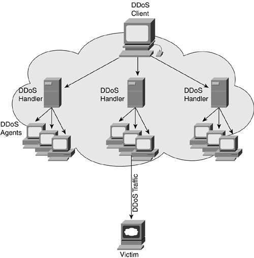
The DDoS client is used by the person who orchestrates an attack as the initial starting point. The handler is a compromised host with a special program running on it. Each handler is capable of controlling multiple agents. An agent is a compromised host that is also running a special program. Each agent is responsible for generating a stream of packets that is directed toward the intended victim.
Many of these attacks are now either semiautomatic or completely automatic. In semiautomatic DDoS attacks, the intruder typically uses automatic tools to scan and compromise vulnerable machines and infect these machines with the attack code. At some later time, the machines with the attack code are used to launch a widely distributed attack. Even more problematic are the completely automatic attacks, where the need for later communication with attack machines is bypassed. The attack code used to infect machines already contains the time the attack will be launched, the type of attack, and preprogrammed attack duration and destinations.
To facilitate DDoS, the attackers need to have several hundred to several thousand compromised hosts. Because often an automated process is used, attackers can compromise and install the tool on a single host in less than 5 seconds. In other words, several thousand hosts can be compromised in less than 1 hour. Figure 5-9 shows an example of such an attack.
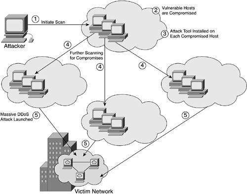
The steps taken to launch this automated attack are as follows:
The attacker initiates a scan phase in which a large number of hosts (on the order of 100,000 or more) are probed for a known vulnerability.
The vulnerable hosts are compromised to gain unauthorized access.
The attack tool is installed on each host.
The compromised hosts are used for further scanning and compromises.
The attack is launched and causes major disruption for corporate business.
The following are common programs that intruders use to facilitate DDoS attacks. Detailed information about these programs can be found at the websites listed:
Trinoo (http://staff.washington.edu/dittrich/misc/trinoo.analysis)—. Trinoo is an attack tool released in late December 1999 that performs a DDoS attack. Trinoo's master (handler) component is typically installed on a compromised computer. Mostly, the compromise stemmed from exploiting buffer overflow bugs in varying UNIX systems, although now this tool is also available on compromised Windows platforms. Trinoo's master component identifies potential targets, creates a script that performs the exploit, and installs the Trinoo daemons (agents). The master then performs the attack. It is capable of broadcasting many UDP packets to a designated or targeted computer via its handlers. The targeted computer tries to process and respond to these invalid UDP packets with “ICMP port unreachable” messages for each UDP packet. Because it has to respond to so many of them, it eventually runs out of network bandwidth, which results in a denial of service.
Trinoo also has a client component that is used to control the master component. This enables the intruder to control multiple master components remotely.
NOTE
The port numbers listed here are the default ports for these tools. Use these ports for orientation and example only, because the port numbers can easily be changed.
Clients, handlers, and agents use the following ports to communicate:
TFN (http://staff.washington.edu/dittrich/misc/tfn.analysis)—. The Tribal Flood Network, or TFN, is made up of client and daemon programs that implement a DDoS tool capable of causing ICMP flood, SYN flood, UDP flood, and Smurf-style attacks. Communication between clients, handlers, and agents use ICMP echo and ICMP echo-reply packets. The handler can manipulate the IP identification number and payload of the ICMP echo-reply to identify the type of attack to be launched. TFN can also spoof the source IP address to hide the origin of the attack.
TFN2K—. This is a newer variant of the TFN tool. Communication between clients, handlers, and agents does not use any specific port (it may be supplied on runtime or may be chosen randomly by a program), but is a combination of UDP, ICMP, and TCP packets.
Stacheldraht—. Stacheldraht is a DDoS tool that combines features from Trinoo and the original TFN tool. In addition, it can encrypt communication between the attacker client and Stacheldraht masters and provides automated updates of the agents.
clients, handlers, and agents use the following ports to communicate:
You can find a comprehensive list of DDoS tools and their variants at http://packetstormsecurity.nl/distributed/.
DDoS attacks are extremely hard to trace; and due to the variety of mechanisms used to perform this type of attack, these attacks are continuing to be an interesting problem for the research community but a never-ending source of pain for people running networks. However, the first rule of thumb is don't panic! This threat is real and it is a difficult one to mitigate. Yet, you can deploy mechanisms to thwart many attemps. Due to the exceptional nature of these attacks, Appendix D, “Mitigating DDoS Attacks,” is solely devoted to a discussion of DDoS attack mitigation techniques in a corporate network infrastructure.
You might also want to refer to a comprehensive paper describing DDoS attacks and DDoS defense mechanisms authored by Jelena Mirkovic, Janice Martin, and Peter Reicher from UCLA at http://lasr.cs.ucla.edu/ddos/ucla_tech_report_020018.pdf.
Understanding some of the motivations for an attack can give you some insight about which areas of the network are vulnerable and what actions an intruder will most likely take. The perception is that, in many cases, the attacks occur from the external Internet. Therefore, a firewall between the Internet and the trusted corporate network is a key element in limiting where the attacks can originate. Firewalls are important elements in network security, but securing a network requires looking at the entire system as a whole.
Some of the more common motivations for attacks include the following:
Greed—. The intruder is hired by someone to break into a corporate network to steal or alter information for the exchange of large sums of money.
Prank—. The intruder is bored and computer savvy and tries to gain access to any interesting sites.
Notoriety—. The intruder is very computer savvy and tries to break into known hard-to-penetrate areas to prove his competence. Success in an attack can then gain the intruder the respect and acceptance of his peers.
Revenge—. The intruder has been laid off, fired, demoted, or in some way treated unfairly. The more common of these kinds of attacks result in damaging valuable information or causing disruption of services.
Ignorance—. The intruder is learning about computers and networking and stumbles on some weakness, possibly causing harm by destroying data or performing an illegal act.
There is a large range of motivations for attacks. When looking to secure your corporate infrastructure, consider all these motivations as possible threats.
Attacks exploit weaknesses in systems. These weaknesses can be caused by poorly designed networks or by poor planning. A good practice is to prevent any unauthorized system or user from gaining access to the network where weaknesses in products and technologies can be exploited.
Spoofing attacks are well known on the Internet side of the world. Spoofing involves providing false information about a person's or host's identity to obtain unauthorized access to a system. Spoofing can be done by just generating packets with bogus source addresses or by exploiting a known behavior of a protocol's weakness. Some of the more common attacks are described in this section. Because understanding the IP protocol suite is a key element in most attacks, this section describes the protocol suite along with the weaknesses of each protocol (such as TCP, ICMP, UDP, DNS, NNTP, HTTP, SMTP, FTP, NFS/NIS, and X Windows). You can find a more thorough study of these protocol weaknesses in Firewalls and Internet Security: Repelling the Wily Hacker, Second Edition by William Cheswick and Steven Bellovin (Addison Wesley Professional, 2003).
Internet Protocol (IP) is a packet-based protocol used to exchange data over computer networks. IP handles addressing, fragmentation, reassembly, and protocol demultiplexing. It is the foundation on which all other IP protocols (collectively referred to as the IP protocol suite) are built. As a network layer protocol, IP handles the addressing and controls information to allow data packets to move around the network (commonly referred to as IP routing). Figure 5-10 shows the IP header format.

The Transmission Control Protocol (TCP) is built on the IP layer. TCP is a connection-oriented protocol that specifies the format of data and acknowledgments used in the transfer of data. TCP also specifies the procedures that the computers use to ensure that the data arrives reliably. TCP allows multiple applications on a system to communicate concurrently because it handles all demultiplexing of the incoming traffic among the application programs. Figure 5-11 shows the TCP header format, which starts at the data portion immediately following the IP header.
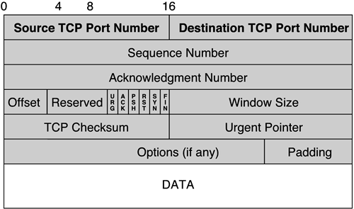
Six bits (flags) in the TCP header tell how to interpret other fields in the header. Table 5-3 lists these flags.
The SYN and ACK flags are of interest in the following section.
To establish a TCP/IP connection, a three-way handshake must occur between the two communicating machines. Each packet of the three-way handshake contains a sequence number; sequence numbers are unique to the connection between the two communicating machines. Figure 5-12 shows a sample three-way handshake scenario.
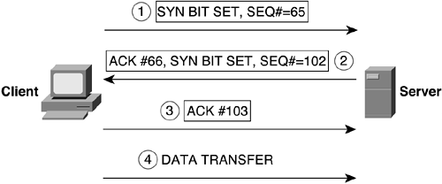
The steps for establishing the initial TCP connection are as follows:
The client initiates a TCP connection to the server. This packet has the SYN bit set. The client is telling the server that the Sequence Number field is valid and should be checked. The client sets the Sequence Number field in the TCP header to its initial sequence number.
The server responds by sending a packet to the client. This packet also has the SYN bit turned on; the server's initial sequence number is the client's initial sequence number plus 1.
The client acknowledges the server's initial sequence number by sending the server's initial sequence number plus 1.
The connection is established, and data transfer takes place.
TCP uses a sequence number for every byte transferred and requires an acknowledgment of the bytes received from the other end upon receipt. The request for acknowledgment enables TCP to guarantee reliable delivery. The receiving end uses the sequence numbers to ensure that the data is in proper order and to eliminate duplicate data bytes.
You can think of TCP sequence numbers as 32-bit counters. These counters range from 0 to 4,294,967,295. Every byte of data exchanged across a TCP connection (as well as certain flags) is sequenced. The Sequence Number field in the TCP header contains the sequence number of the first byte of data in the TCP segment. The Acknowledgment (ACK) field in the TCP header holds the value of next expected sequence number, and also acknowledges all data up through this ACK number minus 1.
TCP uses the concept of window advertisement for flow control. That is, TCP uses a sliding window to tell the other end how much data it can buffer. Because the window size is 16 bits, a receiving TCP can advertise up to a maximum of 65,535 bytes. Window advertisement can be thought of as an advertisement from one TCP implementation to the other of how high acceptable sequence numbers can be.
Many TCP/IP implementations follow a predictable pattern for picking sequence numbers. When a host is bootstrapped, the initial sequence number is 1. The initial sequence number is incremented by 128,000 every second, which causes the 32-bit initial sequence number counter to wrap every 9.32 hours if no connections occur. Each time a connection is initiated, however, the counter is incremented by 64,000.
If sequence numbers were chosen at random when a connection arrived, no guarantees could be made that the sequence numbers would be different from a previous incarnation.
If an attacker wants to determine the sequencing pattern, all she has to do is establish a number of legitimate connections to a machine and track the sequence numbers used.
When an attacker knows the pattern for a sequence number, it is fairly easy to impersonate another host. Figure 5-13 shows such a scenario.

The steps for impersonating a host are as follows:
The intruder establishes a valid TCP connection to the server to figure out the sequence number pattern.
The intruder starts the attack by generating a TCP connection request using a spoofed source address. Often, the intruder picks a trusted host's address and initiates a DoS attack on that host to render it incapacitated.
The server responds to the connection request. However, because the trusted host is under a DoS attack, it cannot reply. If it actually could process the SYN/ACK packet, it would consider it an error and send a reset for the TCP connection.
The intruder waits a certain amount of time to ensure that the server has sent its reply and then responds with the correctly guessed sequence number.
If the intruder is correct in guessing the sequence number, the server is compromised and illegal data transfer can begin.
Because the sequence numbers are not chosen randomly (or incremented randomly), this attack works—although it does take some skill to carry out. Steven M. Bellovin, coauthor of Firewalls and Internet Security, describes a fix for TCP in RFC 1948 that involves partitioning the sequence number space. Each connection has its own separate sequence number space. The sequence numbers are still incremented as before; however, there is no obvious or implied relationship between the numbering in these spaces.
The best defense against spoofing is to enable packet filters at the entry and exit points of your networks. The external entry point filters should explicitly deny any inbound packets (packets coming in from the external Internet) that claim to originate from a host within the internal network. The internal exit point filters should permit only outbound packets (packets destined from the internal network to the Internet) that originate from a host within the internal network.
Session hijacking is a special case of TCP/IP spoofing, and the hijacking is much easier than sequence number spoofing. An intruder monitors a session between two communicating hosts and injects traffic that appears to come from one of those hosts, effectively stealing the session from one of the hosts. The legitimate host is dropped from the connection, and the intruder continues the session with the same access privileges as the legitimate host.
Session hijacking is very difficult to detect. The best defense is to use confidentiality security services and encrypt the data for securing sessions.
When a normal TCP connection starts, a destination host receives a SYN (synchronize/start) packet from a source host and sends back a SYN/ACK (synchronize acknowledge) packet. The destination host must then hear an ACK (acknowledge) of the SYN/ACK before the connection is established. This exchange is the TCP three-way handshake, described earlier in this chapter.
While waiting for the ACK to the SYN/ACK, a connection queue of finite size on the destination host keeps track of connections waiting to be completed. This queue typically empties quickly because the ACK is expected to arrive a few milliseconds after the SYN/ACK is sent.
The TCP SYN attack exploits this design by having an attacking source host generate TCP SYN packets with random source addresses toward a victim host. The victim destination host sends a SYN/ACK back to the random source address and adds an entry to the connection queue. Because the SYN/ACK is destined for an incorrect or nonexistent host, the last part of the three-way handshake is never completed, and the entry remains in the connection queue until a timer expires—typically in about 1 minute. By generating phony TCP SYN packets from random IP addresses at a rapid rate, an intruder can fill up the connection queue and deny TCP services (such as e-mail, file transfer, or WWW service) to legitimate users.
There is no easy way to trace the originator of the attack because the IP address of the source is forged. In the network infrastructure, the attack can be constrained to a limited area if a router or firewall intercepts the TCP connection and proxies on behalf of the connection-initiating host to make sure that the connection is valid.
NOTE
A proxy is a device that performs a function on behalf of another device. For example, if the firewall proxies TCP connections on behalf of a web server, the firewall intercepts the TCP connections from a host trying to access the web server and ensures that valid connection requests are made. After it validates the connection requests (usually by completing the connection by proxy), it initiates its own TCP connection request to the web server on behalf of the host. The connection is established, and normal data transfer between the client and server can start without further interference from the proxy. If a TCP SYN attack occurs, the proxy is attacked but not the actual server. Multiple proxies are typically used to mediate communication between the outside world and one or more web servers, to avoid having a TCP SYN attack that cripples the proxy/firewall from disrupting all web server access.
The land.c attack is used to launch DoS attacks against various TCP implementations. The land.c program sends a TCP SYN packet (a connection initiation), giving the target host's address as both the source and destination and using the same port on the target host as both the source and destination. This can cause many operating systems to hang in some way.
In all cases, the TCP ports reached by the attack must be ports on which services are actually being provided (such as the Telnet port on most systems). Because the attack requires spoofing the target's own address, systems behind effective antispoofing firewalls are safe.
Like TCP, the User Datagram Protocol (UDP) is a transport layer protocol. However, UDP provides an unreliable, connectionless delivery service to transport messages between machines. It does not offer error correction, retransmission, or protection from lost and duplicated packets. UDP was designed for simplicity and speed and to avoid costly overhead associated with connection establishment and teardown. Figure 5-14 shows the UDP header format.
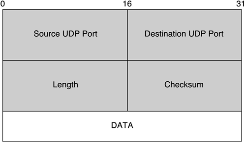
Because there is no control over how fast UDP messages are sent, and there are no connection establishment handshakes or sequence numbers, UDP packets are much easier to spoof than TCP packets. Therefore, it is wise to set up packet filters at the entry and exit points of a campus network to specifically permit and deny UDP-based applications.
The Internet Control Message Protocol (ICMP) is used by the IP layer to exchange control messages. ICMP is also used for some popular diagnostic tools such as ping and traceroute. Figure 5-15 shows an example of an ICMP packet.
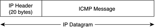
The ICMP message is encapsulated within the IP packet. As provided by RFC 791, IP packets can be up to 65,535 (216 – 1) octets long; this packet length includes the header length (typically 20 octets if no IP options are specified). Packets bigger than the maximum transmission unit (MTU) are fragmented by the transmitter into smaller packets, which are later reassembled by the receiver. The MTU varies for different media types. Table 5-4 shows sample MTUs for different media types.
The Ping of Death is an attack that exploits the fragmentation vulnerability of large ICMP echo request (that is, “ping”) packets. Figure 5-16 shows a sample ICMP echo request packet.

The ICMP echo request packet consists of eight octets of ICMP header information followed by the number of data octets in the ping request. The maximum allowable size of the data area is therefore calculated this way:
(65,535 – 20 – 8) = 65,507 octets
The problem is that it is possible to send an illegal ICMP echo packet with more than 65,507 octets of data because of the way the fragmentation is performed. The fragmentation relies on an offset value in each fragment to determine where the individual fragment goes when it is reassembled. Therefore, on the last fragment, it is possible to combine a valid offset with a suitable fragment size so that the following is true:
(Offset + Size) > 65,535
Because typical machines don't process the packet until they have all the fragments and have tried to reassemble them, there is the possibility of the overflow of 16-bit internal variables, which can lead to system crashes, reboots, kernel dumps, and other unwarranted behavior.
NOTE
This vulnerability is not restricted to the ping packet. The problem can be exploited by sending any large IP datagram packet.
A temporary fix to prevent the Ping of Death is to block ping packets at the ingress points to the corporate network. The ideal solution is to secure the TCP/IP implementation against overflow when reconstructing IP fragments.
The Smurf attack starts with a perpetrator sending a large number of spoofed ICMP echo requests to broadcast addresses, hoping that these packets will be magnified and sent to the spoofed addresses. If the routing device delivering traffic to those broadcast addresses performs the Layer 3 broadcast to Layer 2 broadcast function, most hosts on that IP network will reply to the ICMP echo request with an ICMP echo-reply each, multiplying the traffic by the number of hosts responding. On a multiaccess broadcast network, there could potentially be hundreds of machines replying to each echo packet.
Turning off directed broadcast capability in the network infrastructure is one way to deter this kind of attack.
Teardrop.c is a program that results in another fragmentation attack. It works by exploiting a reassembly bug with overlapping fragments and causes the targeted system to crash or hang. A specific instance of a teardrop program is newtear.c, which is just a specific case in which the first fragment starts at offset 0 and the second fragment is within the TCP header.
The original teardrop.c program used fragmented ICMP packets, but people seem to have created all kinds of variants. The basic attack works for any IP protocol type because it hits the IP layer itself.
If broadcast addresses are used, turning off directed broadcast capability in the network infrastructure is one way to deter this kind of attack. However, the ideal solution is to secure the TCP/IP implementation against problems when reassembling overlapping IP fragments.
The Domain Name System (DNS) protocol is used to resolve host names and IP addresses. DNS servers are probably one of the most common targets for gathering reconnaissance information about hosts for later exploit efforts. DNS differs from a normal client/server application in that there may be interactions with other intermediaries before a response is obtained. When a client issues a DNS query, a DNS server accepts the query, possibly interacts with one or more additional DNS servers, and when it finally receives the response to the query, it forwards it to the client.
DNS is a globally distributed database system that depends on the coopertaive interaction of many DNS servers to store records about domains and to communicate with each other. A domain is a subset of DNS records associated with a logical grouping, such as illustrated in Figure 5-17.

The domain names have a hierarchical structure where the “top-level” domains correspond to classes of users or countries. Thirteen root servers, distributed around the world, are at the top of the domain tree. These top-level domains register “subdomains” and check that the name is unique. They also keep track of the authoritative name servers for subdomains. An authoritative name server is a DNS server that owns and maintains DNS records for a given subdomain. Each domain must have a primary domain server; however, for redundancy, one or more secondary servers are usually created. These secondary servers can be used to load share in responding to DNS queries. DNS servers cache (that is, save) responses that they receive to make the resolution process more efficient. Each response of a DNS record has a time-to-live (TTL) value that is set by the responding DNS server. DNS servers that update records more often are more likely to have lower TTL values than relatively static servers have.
UDP is the protocol used for the majority of the DNS traffic because the queries and responses are often short and the application itself can tolerate lost data. When anticipated data is not received, a new DNS query is issued. Both source and destination ports are UDP 53.
DNS information is maintained on the primary server in flat text files. The secondary server periodically contacts the primary name server to see whether any updates have been made for a particular domain. If so, the updated DNS records are transferred using zone transfers. Zone transfers are done via TCP because there is usually a large amount of data and the transfer needs to be reliable. Zone information is valuable data that a malicious user could easily misuse. To prevent unauthorized zone transfers, newer releases of BIND have configurable parameters that enable an administrator to specify IP numbers or subnets authorized to do zone transfers. Additionally, a network administrator could block inbound traffic to TCP port 53. However, this may block other legitimate traffic as discussed later.
Generally a default name server is configured on every client machine. The gethostbyname call is sent from the client machine to the default DNS server. Assuming that the default server has no knowledge of the host's associated domain, it must contact a root name server. Root name servers maintain a mapping between the domain names and their respective authoritative servers. When the root name server returns a referral, the configured default DNS server then queries the authoritative name server and receives an authoritative answer, the IP address.
Figure 5-18 illustrates the steps for resolving a typical DNS query.
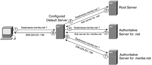
The following steps are carried out for the initial query to find the IP address for seabreeze.merike.net:
The querying host (aka resolver) asks the question to the configured default DNS server.
The default DNS server does not know the answer, and forwards the request to a root name server.
The root server answers with the name (and the address) of the authoritative DNS server for .net.
The default DNS server now queries the authoritative .net server.
The authoritative .net server replies with a referral to for the authoritative .merike.net server.
The default DNS server repeats the query to the authoritative .merike.net server.
The authoritative .merike.net server gives the IP address.
The default DNS server forwards the reply to the querying host.
DNS queries can be recursive or iterative. If a DNS server is configured to be recursive, it tries and queries all known referrences of name servers that could possibly have the answer to a query. The name server must follow all the references until it finds a name server that has the answer and then respond back to the original requester. In an iterative query, if the name server doesn't have the answer, it returns to the querying server a reference of another name server that possibly has the answer to the query. The queried name server does not pursue finding the answer.
NOTE
Recursive DNS queries can lead to DNS cache poisoning. Because DNS uses UDP, it is trivial to determine the sequence number and create an invalid entry. Because many DNS servers are configured with recursive lookups, malicious user can make a DNS query and inject a bogus entry while the query recipient does a recursive DNS lookup. It is recommended not to allow recursive lookups.
How to secure your DNS infrastructure is beyond the scope of this book. However, you do need to be aware that a number of DNS vulnerabilities exist, including corrupting the data, unauthorized updates, impersonating a primary name server, cache pollution by data spoofing, and cache impersonation. DNS data can be spoofed and corrupted on its way between server and resolver or forwarder because the current DNS protocol does not enable you to check the validity of DNS data. Many of these vulneranilities are addressed in the DNS Security (DNSSEC) standard, described in RFC 2535. It provides better authentication mechanisms based on cryptographic signatures to validate the integrity and origin of the DNS data. Currently, the work has not yet been widely adopted; however, it is going through some modifications, and the hope is that it will become widely adopted by the community.
At the network infrastructure level, some filtering can be done to provide some small measure of security. The maximum size of a UDP DNS response is 512 bytes. Of these, a minumum of 20 bytes must be reserved for the IP header, and 8 bytes must be reserved for the UDP header. Therefore, the maximum DNS message can only be 484 bytes. If a DNS resource record exceeds this size, it will be truncated and rather than send UDP fragments, the information is sent via TCP. If inbound traffic to TCP port 53 is blocked (both source and destination port) to prevent unauthorized zone transfers, you also block any external host from resolving large responses. To avoid this problem, block traffic to destination port 53 only and allow traffic to source port 53 that already has an established connection.
Most Usenet traffic uses the Network News Transfer Protocol (NNTP) to send messages between news servers and between servers and newsreaders. Because the control protocol used for NNTP does not provide for any authentication, it can be easy to cancel messages before they are posted, create new unauthorized newsgroups, or delete existing newsgroups from the server.
Servers exist that can provide restrictions on who can post to a group based on their user ID or network address. These servers can be used for authenticated access to read and receive news. Local newsgroups should be placed on an internal secure news server; updates from other news services should be received through packet filters that can restrict which machines communicate to it from outside the corporate infrastructure.
All electronic mail on the Internet is based on the Simple Mail Transfer Protocol (SMTP). Most email programs lack authentication, integrity, and confidentiality services unless special programs such as S/MIME or Pretty Good Privacy (PGP) programs are used. If these programs are not used, authentication, integrity, and confidentiality services can still be provided by using IP Security (IPsec, RFC 2401–2410 ) on routers and firewalls and by specifying that all e-mail traffic be authenticated and encrypted. Although the security services provided by IPsec are not equivalent to those provided by either PGP or S/MIME, they provide some security controls at the network infrastructure level.
A large contingency of e-mail attacks are based on e-mail bombing or spamming. E-mail bombing is characterized by abusers repeatedly sending an identical e-mail message to a particular address. E-mail spamming is a variant of bombing; it refers to sending e-mail to hundreds or thousands of users (or to lists that expand to that many users). E-mail spamming can be made worse if recipients reply to the e-mail, causing all the original addresses to receive the reply.
When large amounts of e-mail are directed to or through a single site, the site may suffer a denial of service through loss of network connectivity, system crashes, or failure of a service because of these factors:
Overloading network connections
Using all available system resources
Filling the disk as a result of multiple postings and resulting syslog entries
A recent mass-mailing, network-aware worm named W32.Sobig.F infected thousands of machines in August 2003. The worm used its own SMTP engine to propagate and sent itself to multiple addresses. The spoofed From addresses and the Send To addresses were both taken from the files found on the compromised computer.
Spamming or bombing attacks cannot be prevented, but you can minimize the number of machines available to an intruder for an SMTP-based attack. If your site uses a small number of e-mail servers, you may want to configure your ingress (entry from the Internet to the corporate network) and egress (exit from the corporate network to the Internet) points to ensure that SMTP connections from the outside can be made only to your central e-mail hubs and to none of your other systems. Additionally, you may want to configure your email server to block or remove email that contains file attachments that are commonly used to spread viruses, such as .vbs, .bat, .exe, .pif, and .scr files.
You can find more detailed information on SPAM attacks and deterrents at the following addresses: http://spam.abuse.net/ and http://www.cauce.org/.
The File Transfer Protocol (FTP) is a TCP-based application program often used to transmit and receive large data files. The protocol uses two TCP connections, as shown in Figure 5-19:
One connection for the initial FTP control connection, which is initiated by the client to the server
The other connection for the FTP data connection, which is initiated from the server back to the client

Most common FTP implementations create a new FTP data connection for each file transfer and also require a new port number to be used for each of these new FTP data connections. These requirements can cause problems for restricted environments that want to block externally initiated FTP connections. The packet filters block the incoming data connection back from the server so that file transfer no longer works.
To circumvent this problem, passive mode FTP was developed. With passive mode FTP, the client initiates both the control connection and the data connection so that a packet-filtering firewall can provide some protection and not block data transfers.
Be aware that FTP is an insecure protocol and that passwords are sent as plaintext between your user sessions and any FTP server you are likely to run. Even if you insist that users connect to your servers using Secure Shell (SSH), if their FTP and shell login passwords are the same (which is the default), someone snooping around can gain access to your system via SSH by sniffing FTP user sessions for passwords.
It is best to try and avoid FTP completely. Where possible, use the Secure Copy Protocol (SCP), which is built in to many SSH daemons.
The Remote Procedure Call (RPC) service is a programming interface for a client/server relationship between two interfaces which allows a program running on one computer to seamlessly execute code on a remote system. It can utilize either TCP or UDP as its transport protocol. RPC is widely used for many distributed network services and is often the culprit for security breaches since in UNIX environments many RPC services execute with root privileges and can provide an attacker with unauthorized root access. RPC programs do not perform sufficient error checking or input validation services and are often exploited through buffer overflow attacks. The UNIX portmap service, which uses TCP or UDP port 111 keeps track of the location of various RPC services by port and potential attackers often use the portmap service to locate the procedures they want to attack. A secure version of portmapper is available and should be used. To mitigate reconnaissance attempts using portmap, blocking TCP and UDP port 111 at network edges can avert many potential attacks. In addition, it is advisable to block RPC loopback ports 32770 through 32789 (TCP and UDP).
More recent and widespread worms involving RPC are the notorious Blaster.D and Nachi worms which infected devices running the Microsoft operating system. These worms exploit the DCOM RPC vulnerability which is described in Microsoft Security Bulletin MS03-026 at http://www.microsoft.com/technet/treeview/default.asp?url=/technet/security/bulletin/MS03-026.asp.
Similar to the UNIX RPC issues, the Microsoft vulnerability results because the Windows RPC service does not properly check message inputs under certain circumstances. Both Blaster.D and Nachi exploit the RPC DCOM vulnerability to gain access to a system. After a vulnerable system is compromised, the worms use TFTP to download the rest of its operating components and attempts to spread themselves across the network. While Blaster.D blindly attempts to reach addresses on the compromised hosts' network, the Nachi worm first sends out a series of pings to verify that target hosts are actually online and subsequently results in an ICMP DoS on the compromised hosts' network. To mitigate attacks based on Blaster.D and Nachi, it is recommended to block outbound traffic of the following ports at enterprise network perimeters:
135 (UDP and TCP)
137 (UDP and TCP)
139 (UDP and TCP)
445 (UDP and TCP)
593 (TCP)
69 (UDP): TFTP traffic to prevent the worm version of the exploit from downloading code to a newly infected host
4444 (TCP): The exploit uses this to provide command line access to a Windows target host
NOTE
To avert exploits which may make use of any host vulnerability it is extremely important to understand the services, which need to be made accessible to the Internet. The best defense is to apply filters at network perimeters (edges), which deny everything and permit only the services, which are required. However, this can be too restrictive in many circumstances and needs careful consideration. The following URL lists the common TCP and UDP ports used for Windows services, and it is listed here to help you make appropriate decisions in enterprise networks that largely use the Microsoft operating system:
The Network File System (NFS) and the Network Information System (NIS) are commonly used services in UNIX environments. NFS is used to access remote file systems by allowing users to mount remote file systems so that they can be accessed locally. NIS is used to establish central services and databases in client/server relationships. (Typically, these services include user account information and passwords.) NIS and NFS are often used together to help enforce file permissions on mounted systems.
Both NFS and NIS use UDP as their underlying protocol. In typical configurations, there is limited authentication on either end of the connection. These services are extremely insecure; this kind of traffic should never be allowed through the entrance or exit points of the corporate network.
X Window System is one of the most commonly used windowing systems. The X server offers resources such as the keyboard, the mouse, and the windows on the screen to X clients. The server accepts requests from the client for keyboard input, screen output, or mouse movement and returns the results of these requests. The X11 protocol has been adopted by many of the major workstation vendors for displaying network graphics and is the common element upon which each vendor's graphical user interface is based.
X Window System requires a reliable bidirectional stream protocol such as TCP. The communication between the client and the server consists of 8-bit bytes exchanged across a TCP connection.
Because of limited authentication inherent in the X11 protocol, it is possible for someone with access to the network to connect directly to the X server and either view or modify ongoing communication between the server and the X client.
In a network infrastructure, limiting X11 traffic to only internal hosts is one way to limit these kinds of attacks.
This section covers attacks that exploit weaknesses in poorly designed networks, detailing threats to specific networking scenarios pertaining to VPNs, wireless networks, and Voice over IP (VoIP) networks to emphasize vulnerabilities in these network designs. In addition, some threats to routing protocols are discussed. Implementation details for building secure VPN, wireless, and VoIP networks are discussed in Chapter 12, “Securing VPN, Wireless, and VoIP Networks.”
When discussing vulnerabilities specific to deploying VPNs, the main issue revolves around understanding where the VPN tunnel starts and ends and where the traffic is exposed. In an ideal situation, the VPN tunnel will be created end-to-end; in many cases, however, the tunnel endpoints are both intermediary gateways or a VPN concentrator.
Unauthorized access via VPNs would likely result from obtaining credentials, such as a username/password, for a given user or device. Typically, more robust authentication and authorization mechanisms would be used to make it harder to get access to the credentials used. Laptops being used for remote secure access can compromise a corporate VPN if they are not sufficiently protected. Often, the credentials used to authenticate the device are saved on the laptop via a VPN software package. If the laptop is stolen and the VPN software is not adequately protected on the laptop, a malicious user could easily gain access to the corporate VPN. To provide more protection, any remote user VPN scenario should obtain credentials to authenticate both a given device and individual user before allowing access to the corporate network.
Look at a situation where Layer 2 Tunneling Protocol (L2TP)/IPsec is deployed to create a secure VPN tunnel. Assume that the identity claimed in PPP is a user identity, whereas the identity claimed within Internet Key Exchange (IKE) is a device identity. Although PPP provides initial authentication, it does not provide per-packet authentication, integrity, or replay protection. For IPsec, when the identity asserted in IKE is authenticated, the resulting derived keys are used to provide per-packet authentication, integrity, and replay protection. As a result, the identity verified in the IKE conversation is subsequently verified on reception of each packet. So, in this scenario, because only the device identity is verified on a per-packet basis, there is no way to verify that only the user authenticated within PPP is using the tunnel. In fact, IPsec implementations that only support device authentication typically have no way to enforce traffic segregation. As a result, where device authentication is used, after an L2TP/IPsec tunnel is opened, any user on a multi-user machine will typically be able to send traffic down the tunnel.
If the IPsec implementation supports user authentication, this problem can be averted. When using IPsec with user authentication, the user identity asserted within IKE will be verified on a per-packet basis. To provide segregation of traffic between users when user authentication is used, the client can ensure that only traffic from that particular user is sent down the L2TP tunnel.
Impersonation could be accomplished if the actual key material gets compromised. If a company uses a group shared key for all employees, the shared key is more susceptible to getting compromised and can have a larger impact. It is best to avoid a group shared key whenever possible.
When using IPsec to deploy VPNs, it is still common to use preshared keys for authentication. Use of preshared keys in IKE phase 1 main mode increases vulnerability to man-in-the-middle attacks in remote access situations. In main mode, it is necessary for the derived encryption key to be used prior to the receipt of the identification payload. Therefore, the selection of the preshared key can only be based on information contained in the IP header. However, in remote access situations, dynamic IP address assignment is typical, so it is often not possible to identify the required preshared key based on the IP address.
When preshared keys are used in remote access scenarios, the same preshared key is shared by a group of users and is no longer able to function as an effective shared secret. In this situation, neither the client nor the server identifies itself during IKE phase 1; it is only known that both parties are members of the group with knowledge of the preshared key. This permits anyone with access to the group preshared key to act as a man in the middle.
This vulnerability does not occur in IKE phase 1 aggressive mode because the identity payload is sent earlier in the exchange, and therefore the preshared key can be selected based on the identity. When aggressive mode is used, however, the user identity is exposed and this is often considered undesirable.
As a result, where IKE phase 1 main mode is used with preshared keys, unless PPP performs mutual authentication, the server is not authenticated. This enables a rogue server in possession of the group preshared key to successfully masquerade as the L2TP network server (LNS) and mount a dictionary attack on legacy authentication methods such as Challenge Handshake Authentication Protocol (CHAP). Such an attack could potentially compromise many passwords at a time. This vulnerability is present in some existing IPsec tunnel mode implementations.
To avoid this problem, L2TP/IPsec implementations often do not use a group preshared key for Internet Key Exchange (IKE) authentication to the LNS.
DoS attacks may be directed at critical components in the VPN path, such as a VPN concentrator that could potentially terminates hundreds of VPN connections. If the VPN is created such that certain protocols that are part of the VPN (such as SSL/TLS, SSH, and IPsec) are inherently trusted and could bypass any firewall controls, a malicious user could potentially spoof these types of packets using trusted IP addresses and then use these spoofed packets to launch a DoS attack against internal corporate resources. Never assume that traffic, just by being transported as part of a VPN solution, is secure and can be trusted. How to make appropriate secure VPN design decisions is discussed in more detail in Chapter 12.
Wireless networks have become one of the most interesting targets for security breaches. Most wireless LAN devices ship with all security features disabled, and several websites are documenting all the freely available wireless connections nationwide, giving potential intruders a choice of which site to go tamper with. Although many intruders just exploit these “free” connections as a means to get free Internet access or to hide their identity, others might see this situation as an opportunity to break into networks that otherwise might have been difficult to attack from the Internet because unlike a wired network, wireless networks send data over the air and usually extend beyond the physical boundary of an organization.
Unauthorized access to wireless LANs can be obtained in a number of ways. When strong directional antennas are used, a wireless LAN can reach well outside the buildings that it is designed for, and if WEP is not enabled it is easy to create an environment where traditional physical security controls are ineffective because the packets can be viewed by anyone within radio frequency range.
Most wireless LANs deployed by organizations operate in a mode called “infrastructure.” In this mode, all wireless clients connect through an AP for all communications. You can, however, deploy wireless LAN technology in a way that forms an independent peer-to-peer network, which is more commonly called an ad hoc wireless LAN. In an ad hoc wireless LAN, laptop or desktop computers that are equipped with compatible wireless LAN adapters and are within range of one another can share files directly, without the use of an AP. The range varies, depending on the type of wireless LAN system. Laptop and desktop computers equipped with 802.11b wireless LAN cards can create ad hoc networks if they are within at least 500 feet of one another. Many wireless cards, including some shipped as a default item by PC manufacturers, ship with ad hoc mode enabled by default. Any person who is also configured for ad hoc mode is immediately connected to PCs using these cards and could attempt to gain unauthorized access. In most environments, it would be prudent to disable ad hoc mode wireless LANs.
In the hands of a determined malicious intruder, a rogue AP can be a valuable asset in the attempted compromise of network resources. The principal threat is installing an AP into a network after gaining unauthorized access to a building. The user typically gains access to the building by following behind a user with a valid access badge or by obtaining a guest badge for some other reason. Because APs are relatively small and can be purchased at many electronics outlets worldwide, it is easy for the intruder not only to obtain the AP but also to install it discreetly. Attaching the AP to the underside of a conference-room table and plugging into the live network enables the intruder to break into a network from the relative security of his car in the parking lot. Man-in-the-middle attacks are also easy to carry out. Using a device that can masquerade as a trusted AP, an intruder can easily intercept and manipulate wireless packets.
NOTE
An organization should have a complete wireless network policy in addition to its overall security policy. (Refer to Chapter 6, “Considerations for a Site Security Policy,” and Chapter 7, “Design and Implementation of the Corporate Security Policy,” for more detail on how to create a security policy.) This wireless policy should, at a minimum, disallow the connection of non-IT supported APs into the network. In addition, the IT department needs to conduct regular scans of its office space to check for rogue APs. This includes both physical searches and wireless scans. Several vendors offer tools designed to discover the presence of the wireless APs in a certain area.
The wireless LAN access points can identify every wireless card by its unique Media Access Control (MAC) address. Some APs have MAC address filtering capabilities that require that the cards be registered before the wireless services can be used. However, this introduces administrative nightmares because every AP needs to have this list configured. In addition, all MAC addresses are sent in the clear and there exist programs such as Network Stumbler that a malicious user can use to eavesdrop on a wireless network and to obtain valid MAC addresses. The eavesdropper could then use a wireless LAN card that can be loaded with firmware to define its MAC address. Using this spoofed MAC address, the malicious user can attempt to inject network traffic or spoof legitimate users.
It is easy to interfere with wireless communications. A simple jamming transmitter can easily cause a DoS attack and render communications impossible. For example, consistently sending access requests to an AP, whether successful or not, will eventually exhaust its available radio frequency spectrum and make it unavailable. Other wireless services in the same frequency range can also reduce the range and usable bandwidth of wireless LAN technology, as illustrated in Figure 5-20.

Although by no means a malicious denial of service, those deploying wireless networks need to be aware of other obstructions that could potentially render a network unusable if they are added in an office environment. These include microwave ovens near kitchens, metal file cabinets, and possibly large industrial equipment.
The operation of WEP is described in Chapter 3. The 802.11 standards define WEP as a simple mechanism to protect the communication between wireless LAN APs and network interface cards (NICs). WEP uses the RC-4 encryption algorithm and requires that the same secret key be shared by all communicating parties. To avoid conflicting with U.S. export controls that were in effect at the time the standard was developed, 40-bit encryption keys were required by IEEE 802.11b, although many vendors now support the optional 128-bit standard. These key lengths are not very robust, and WEP can be easily cracked in both 40- and 128-bit variants by using off-the-shelf tools readily available on the Internet.
The IEEE 802.11 standard describes the use of the RC-4 algorithm and key in WEP, but does not specify specific methods for key distribution. Without an automated method for key distribution, any encryption protocol will have implementation problems due to the potential for human error in key input, escrow, and management. As discussed in Chapter 3, 802.1x is being embraced by the wireless LAN vendor community as a potential solution for this key distribution problem.
WEP's biggest problem came with the publication of weaknesses in RC-4 that were discovered by cryptanalysts Fluhrer, Mantin, and Shamir. The first weakness is in the Key Scheduling Algorithm (KSA), which derives the initial state from a variable key size. There exists a large class of keys (weak keys) in which a small part of the secret key determines a large number of bits in the KSA output. This weakness is known as the invariance weakness. The weakness can be exploited by what is termed the FMS attack (Fluhrer, Mantin, Shamir attack), which is illustrated in Figure 5-21 and is described in a paper found at http://www.cs.umd.edu/~waa/class-pubs/rc4_ksaproc.ps.
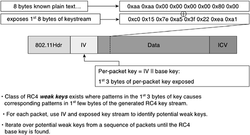
The paper discusses the theoretical derivation of a WEP key in a range of 100,000 to 1,000,000 packets encrypted using the same key. Recent practical implementations of the FMS attack have been able to derive a static WEP key by capturing about a million packets. This is demonstrated in a paper by AT&T Labs and Rice University at http://www.cs.rice.edu/~astubble/wep/wep_attack.pdf. Several independent developers then released their own implementations of the FMS attack; the most popular of these is AirSnort, which can be downloaded at http://airsnort.sourceforge.net/.
The second weakness is related to the first and occurs when part of the key presented to the KSA is exposed to the attacker. Because the initialization vector (IV) for RC-4 is transmitted as plaintext and placed in the 802.11 header, anyone eavesdropping on a wireless LAN can see it. Because the IV is 24 bits long, it provides a range of 16,777,216 possible values. A University of California at Berkeley paper found that when the same IV is used with the same key on an encrypted packet, an eavesdropper can capture the data frames and derive information about the data as well as the network. This is also known as the IV Collision attack and is illustrated in Figure 5-22.

For more information, refer to the University of California at Berkeley paper titled “Security of the WEP Algorithm” at http://www.isaac.cs.berkeley.edu/isaac/wep-faq.html. To prevent attacks due to IV collisions, the base key should be changed before the IVs repeat, and many vendors are implementing proprietary mechanisms to address this issue until newer 802.11 standards incorporating Temporal Key Integrity Protocol (TKIP) and the Advanced Encryption Standard (AES) encryption algorithm are available.
Another concern with WEP is its vulnerability to replay attacks. This is due to the use of the cyclic redundancy check (CRC)-32 checksum function performed by standards-based WEP, as illustrated in Figure 5-23.
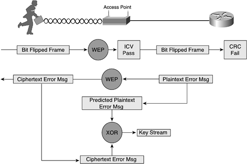
As the previously mentioned paper “Security of the WEP Algorithm” indicates, with CRC-32, it is, “possible to compute the bit difference of two CRCs based on the bit difference of the messages over which they are taken. In other words, flipping bit n in the message results in a deterministic set of bits in the CRC that must be flipped to produce a correct checksum on the modified message. Because flipping bits carries through after an RC-4 decryption, this allows the attacker to flip arbitrary bits in an encrypted message and correctly adjust the checksum so that the resulting message appears valid.”
Wireless networks are being deployed quite rapidly and although the standards work still needs to be completed to make these networks more secure, knowing which threats and vulnerabilites exist can help in deploying a reasonably secure wireless network, as discussed in Chapter 12.
The main issue with voice networks today is that they are generally wide open and require little or no authentication to gain access. The reason for this is that the model chosen for IP voice networks parallels that chosen for legacy voice systems. It is expected that going forward the traditional security features such as strong authentication and encryption will integrate with IP telephony standards. Here we outline some threats to be aware of when deploying VoIP networks.
Voice transport mechanisms generally don't use encryption, which makes it easy to use packet sniffers so that the voice steams can be saved and reassembled for listening. The tool “voice over misconfigured Internet telephones” (also known as vomit), takes an IP phone conversation trace captured by the UNIX tool tcpdump, and reassembles it into a WAV file for easy listening. The phones are not actually misconfigured. Rather, if someone were able to obtain access to the IP data stream at any point in the network, they could eavesdrop.
Another threat constitutes theft of service, and there are numerous methods an intruder could use to accomplish this task. In its most basic form, toll fraud includes an unauthorized user accessing an unattended IP phone to place calls. A more complex scenario might include placing a rogue IP phone or gateway on the network to place unauthorized calls.
Caller identity spoofing can occur when an intruder is able to trick a remote user into believing she is talking to someone when in fact she is really talking to the intruder. This type of attack typically occurs with the intruder assuming the identity of someone who is not familiar to the target. A complex attack would be to first place a rogue IP phone in the network and then via a secondary exploit assume the identity of a valid IP phone (assuming the identity that you want your target to see). It could also be as simple as a bypassing physical building security and using an unattended IP phone!
An IP spoofing attack can occur when an intruder inside or outside a network impersonates the conversations of a trusted computer. An intruder can do this in one of two ways. He uses either an IP address that is within the range of trusted IP addresses for a network or an authorized external IP address that is trusted and to which access is provided to specified resources on a network. IP spoofing attacks are often a launch point for other attacks. The classic example is to launch a DoS attack using spoofed source addresses to hide the intruder's identity. As it relates to IP telephony, without spoof mitigation filters the intruder might be able to spoof the address of the call-processing manager and UDP flood the entire voice segment.
Certainly the most publicized form of attack, DoS attacks are also among the most difficult to completely eliminate. These attacks include the following, all of which were discussed earlier in this chapter:
TCP SYN flood
Ping of Death
UDP fragment flood
ICMP fragment flood
If not properly mitigated, all of these sample DoS attacks could render a voice segment unusable.
This section lists a few inherent insecurities to be aware of when using Session Initiation Protocol (SIP)-based networks. Most of these can be found in the discussion in the security considerations section of the SIP protocol (RFC 3261).
One of the primary limitations of using HTTP Digest in SIP is that the integrity mechanisms in the digest do not work very well for SIP. Specifically, they offer protection of the Request-URI and the method of a message, but not for any of the header fields that user agents would most likely want to secure.
Another limitation of HTTP Digest is the scope of realms. The digest is valuable when a user wants to authenticate himself to a resource with which he has a preexisting association, such as a service provider of which the user is a customer (which is quite a common scenario and thus HTTP Digest provides an extremely useful function).
The largest outstanding defect with the S/MIME mechanism is the lack of a prevalent public key infrastructure for end users. If self-signed certificates (or certificates that cannot be verified by one of the participants in a dialogue) are used, the SIP-based key exchange is susceptible to a man-in-the-middle attack with which an attacker can potentially inspect and modify S/MIME bodies. The attacker needs to intercept the first exchange of keys between the two parties in a dialogue, remove the existing CMS-detached signatures from the request and response, and insert a different CMS-detached signature containing a certificate supplied by the attacker (but which seems to be a certificate for the proper address of record). Each party will think he has exchanged keys with the other, when in fact each has the public key of the attacker.
It is important to note that the attacker can only leverage this vulnerability on the first exchange of keys between two parties; on subsequent occasions, the alteration of the key would be noticeable to the user agents. It would also be difficult for the attacker to remain in the path of all future dialogues between the two parties over time (as potentially days, weeks, or years pass). The S/MIME mechanism allows user agents to send encrypted requests without preamble if they possess a certificate for the destination address of record on their keyring. However, it is possible that any particular device registered for an address of record will not hold the certificate that has been previously used by the device's current user, and that it will therefore be unable to process an encrypted request properly, which could lead to some avoidable error signaling. This is especially likely when an encrypted request is forked.
The keys associated with S/MIME prove most useful when associated with a particular user (an address of record) rather than a device (a user agent). When users move between devices, it may be difficult to transport private keys securely between user agents; how such keys might be acquired by a device is beyond the scope of this discussion.
The most commonly voiced concern about TLS is that it cannot run over UDP; TLS requires a connection-oriented underlying transport protocol and therefore can only be used with TCP for SIP-based networks. It can be problematic for a local outbound proxy server and registrar to maintain many simultaneous long-lived TLS connections with numerous user agents, which introduces scalability concerns for intensive ciphersuites and allows for susceptibility for DoS attacks.
TLS only allows SIP entities to authenticate servers to which they are adjacent; TLS offers strictly hop-by-hop security. Neither TLS, nor any other mechanism specified in the SIP standard, allows clients to authenticate proxy servers to whom they cannot form a direct TCP connection.
NOTE
When SIP is used in a mode where resources can specify that they should be reached securely, the term SIPS is used to designate this secure mode. The SIPS URI scheme adheres to the syntax of the SIP URI, although the scheme string is “sips” rather than “sip.”
Using TLS on every segment of a request path entails that the terminating user agents must be reachable over TLS (perhaps registering with a SIPS URI as a contact address). This is the preferred use of SIPS. Many valid architectures, however, use TLS to secure part of the request path, but rely on some other mechanism for the final hop to a user agent, for example. Therefore, SIPS cannot guarantee that TLS usage will be truly end to end. Note that because many user agents will not accept incoming TLS connections, even those user agents that do support TLS may be required to maintain persistent TLS connections as discussed earlier in this chapter to receive requests over TLS as a user agent.
Ensuring that TLS will be used for all of the request segments up to the target domain is somewhat complex. It is possible that cryptographically authenticated proxy servers along the way that are noncompliant or compromised may choose to disregard the forwarding rules associated with SIPS. Such malicious intermediaries could, for example, retarget a request from a SIPS URI to a SIP URI in an attempt to downgrade security.
Alternatively, an intermediary might legitimately retarget a request from a SIP to a SIPS URI. Recipients of a request whose Request-URI uses the SIPS URI scheme therefore cannot assume on the basis of the Request-URI alone that SIPS was used for the entire request path (from the client onward).
If an attacker corrupts a DNS cache, inserting a fake record set that effectively removes all SIPS records for a proxy server, any SIPS requests that traverse this proxy server may fail. When a user sees that repeated calls to a SIPS address of record (AOR) are failing, however, he could on some devices manually convert the scheme from SIPS to SIP and retry. Of course, there are some safeguards against this (if the destination user agent is truly paranoid it could refuse all non-SIPS requests), but it is a limitation worth noting. On the bright side, users might also divine that “SIPS” would be valid even when they are presented only with a SIP URI.
SIP messages frequently contain sensitive information about their senders—not just what they have to say, but with whom they communicate, when they communicate, and for how long, and from where they participate in sessions. Many applications and their users require that this sort of private information be hidden from any parties that do not need to know it.
There are also less direct ways in which private information can be divulged. If a user or service chooses to be reachable at an address that is guessable from the person's name and organizational affiliation (which describes most AORs), the traditional method of ensuring privacy by having an unlisted “phone number” is compromised. A user location service can infringe on the privacy of the recipient of a session invitation by divulging the user's specific whereabouts to the caller. Therefore, it is important to be able to restrict, on a per-user basis, what kind of location and availability information is given out to certain classes of callers. Note that this is a whole class of problem that is expected to be studied further in ongoing SIP work.
In some cases, users may want to conceal personal information in header fields that convey identity. This can apply not only to the From and related headers representing the originator of the request, but also the To—it may not be appropriate to convey to the final destination a speed-dialing nickname, or an unexpanded identifier for a group of targets, either of which would be removed from the Request-URI as the request is routed, but not changed in the To header field if the two were initially identical. Therefore, check whether the SIP implementation you are using creates a To header field that differs from the Request-URI.
VoIP is being deployed in numerous configurations. Even though the standards work still needs to be completed to make these networks more secure, knowing which threats and vulnerabilites exist can you deploy a reasonably secure VoIP network. as shown in Chapter 12.
Routing protocols have all adopted peer neighbor authentication mechanisms, as discussed in Chapter 4, “Routing Protocol Security.” However, routing infrastructures are still subject to threats involving eavesdropping because no privacy is provided. Also, DoS attacks can be launched with spoofed addresses or invalid routing protocol updates. Using a combination of filtering techniques, neighbor authentication, and IPsec, it is possible to gain more security; however, it is often not thought that the risk in routing update spoofing warrants the added administrative costs of implementing IPsec in current networks.
Finally, it is important to remember the importance of social engineering when considering threats to the corporate network. Consider a scenario in which a financial administrator in a large corporate network gets a phone call from someone saying she is part of the IS department and wants to verify users and passwords. An unwitting employee may think this is a valid request and submit his username and password over the phone to the intruder impersonating someone from the IS department. The intruder can now impersonate the financial administrator and gain access to very confidential data and possibly alter it for her personal gain.
Although some threats to network security are quite sophisticated, it can be very simple to gain access to networks through seemingly innocent social means. Corporate employees should be educated about the company security policy procedures and the importance of authentication methodologies. Employees must understand the ramifications of security breaches so that they are aware of the importance of security procedures. It is the responsibility of the corporation to establish a network security policy and then establish a way to implement that policy.
This chapter examined the various threats to a corporate network by detailing which types of attacks and vulnerabilities are common and what you can do at a policy level to guarantee some degree of safe networking. The types of threats usually come in the form of unauthorized access, impersonation, or DoS. Understanding some of the motivations for an attack can give you insight about which areas of the network are vulnerable and what actions an intruder may take. The more common vulnerabilities were detailed to help you evaluate your susceptibility—this can be invaluable in determining which steps you should take to safeguard your most exposed areas.
The following questions provide you with an opportunity to test your knowledge of the topics covered in this chapter. You can find the answers to these questions in Appendix E, “Answers to Review Questions.”