
CHAPTER 9
A PS2 Keyboard CW Encoder
In 2006, the Federal Communications Commission (FCC) dropped the Morse code requirements for amateur radio licenses. People have different views about dropping the code requirement as part of becoming a licensed radio amateur. It seems reasonable to assume that the disappearance of the requirement probably did bring more people into amateur radio. However, not knowing Morse code has its downside, too.
First, you can buy a low power continuous wave (CW) transceiver for less than $50, making the entry cost into the hobby fairly inexpensive. Second, CW affords more “miles per watt” than other transmission modes. With a good antenna system and favorable band conditions, QRP rigs that output a couple of watts are capable of worldwide communications. Third, CW rigs are well suited to emergency operation since they offer reliable communication with relatively low power requirements. Battery operation is routinely done with many QRP rigs. (Chapter 17 features a project that uses solar power for emergency communications.) Also, for certain classes of licenses, only CW can be used in certain segments of the bands. Finally, we feel that amateurs who haven’t experienced CW operation have really missed out on something. We can’t really express the feeling clearly, but there is an inner satisfaction of being able to communicate in Morse code.
We actually started wondering about CW and keying in general when a friend of ours with a wrist injury said that he had backed off of using CW because of the wrist pain. (He preferred a straight key.) Like many other hams, however, he could type quite well and he could do so without much pain. Hence, the project of this chapter. While typing on an old PS2 keyboard may not be your exact cup of tea, the project does show how easy it can be to interface an external device to an Arduino plus how to isolate your rig from the Arduino. Finally, there are some interesting software techniques used in this project’s software that are worth knowing.
The PS2 Keyboard
Most keyboards for today’s computers are USB devices. Unfortunately, the USB specification and interfacing to a USB port is a fairly complex process. PS2 keyboards, on the other hand, are easy to interface. Another advantage is that you can buy PS2 keyboards fairly inexpensively. The keyboard we use in this project was picked up at a church donation center for $2.
The pin out for a PS2 connector is shown in Figure 9-1.
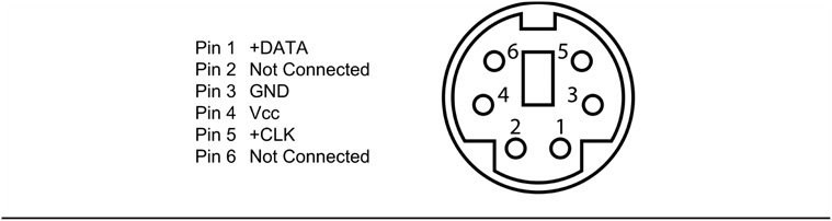
FIGURE 9-1 PS2 connector (facing female socket).
Only four of the six pins are needed to interface the PS2 keyboard to the Arduino. Figure 9-2 shows two of the female PS2 sockets that are available at a fairly reasonable cost.

FIGURE 9-2 PS2 connector sockets.
We chose to use the connector on the right in Figure 9-2 because we were able to buy 10 of them for less than $0.30 each and they are easily fitted to a perf board. (We called the sockets “PS2 boxes” but technically, it is called a “6-pin Mini-DIN” connector.) The connector on the left is more expensive but would be better suited for mounting the electronics in some kind of enclosure rather than on perf board.
The PS2 box connector we are using has the leads coming from the bottom of the connector in the pattern shown in Figure 9-3. The pin out interpretation is that shown in Figure 9-1. Note that the pins shown in Figure 9-3 are as viewed from the bottom of the connector. If you are unsure of the pin outs, just stick a piece of wire in each socket hole and use a multimeter to check the pins. The PS2 box connectors are a standard connector so there shouldn’t be any surprises. We tied the four pins from the PS2 box to a 4-pin header to make it easier to connect it to the Arduino during testing. The small perf board is shown in Figure 9-4.
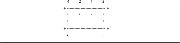
FIGURE 9-3 PS2 pin out for PS2 boxes (bottom view).
Reading from left to right in Figure 9-4, the first pin connects to the PS2 ground connection (pin 3). The second header pin connects to the PS2 clock pin (pin 5). The third pin connects to the data pin (pin 1), and the final pin connects to the VCC positive voltage pin (pin 4). Pins 2 and 6 are not connected.
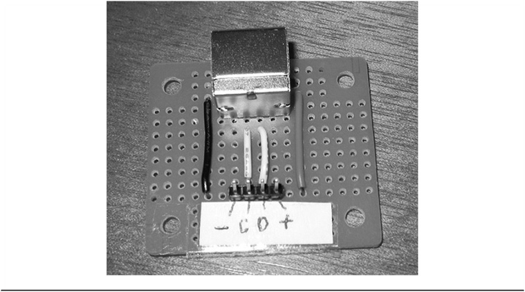
FIGURE 9-4 Connecting the PS2 pins to the header.
Testing the PS2 Connector
Once you have connected the PS2 connector leads to the header pins, you can connect the keyboard’s PS2 male connector to the PS2 box female connector. Connect the ground header pin to the Arduino GND pin and the VCC positive voltage header pin to the Arduino 5 V pin. When you attach the USB connector to the Arduino board, you will likely see one or more LEDs on the keyboard briefly flash once. That’s a good sign, because it not only means you’ve got the power connections wired correctly, but also that your keyboard is alive and well. (For $2, there were some thoughts that our used keyboard might be DOA.)
Since the power test was passed, go ahead and connect the clock pin (pin 5 on the PS2 connector and the “C” pin in Figure 9-4) to pin 3 on the Arduino. Also connect the data pin (pin 1 on the PS2 connector and the “D” pin in Figure 9-4) to pin 4 on the Arduino. You are now ready for a more robust test of the keyboard. That test, however, involves using the software that supports the keyboard CW encoder. We explain how to perform that test later in the chapter.
The PS2 Keyboard Encoder Software
The software used to convert the keystrokes sent by the keyboard to their Morse code equivalent is shown in Listing 9-1. The code is a slightly modified Open Source version written by Mark VandeWettering, K6HX. He has provided some nice features with the keyboard, including a “type-ahead” buffer feature that lets you type in characters faster than the selected code speed outputs them to the transmitter. Before we get into the details about the code shown in Listing 9-1, you need an additional Open Source library specifically written for the PS2 keyboard.

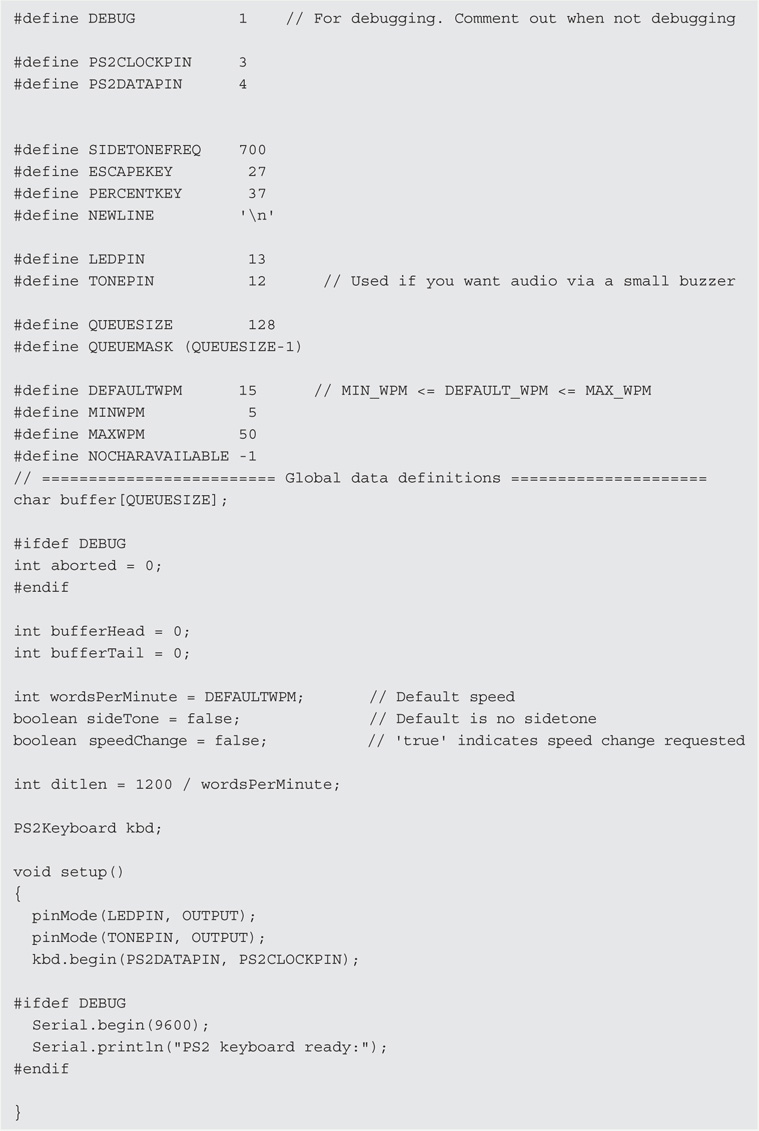
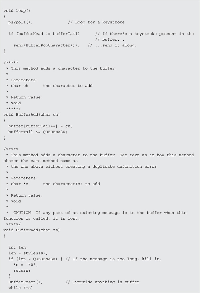

LISTING 9-1 The PS2 encoder program.
Adding the PS2 Library Code to Your IDE
The first thing you need to do before you attempt to compile the code in Listing 9-1 is download the keyboard library files used in the program. You can download these files without charge from:
http://www.pjrc.com/teensy/td_libs_PS2Keyboard.html
When the page loads in your browser, you can see a download link for the PS2Keyboard.zip file. The browser does the usual inquiry about where you want to save the downloaded file. We usually create a directory that reflects the nature of whatever it is we are downloading. In this case, you might create a new directory name PS2KeyboardLibrary. When the download finishes, use whatever program you have that can extract the compressed files from the ZIP file. Under Windows, simply double-click on the file and the files are extracted.
If you are using Windows, load Windows Explorer if you haven’t already done so. (You can run Windows Explorer by right-clicking on the Windows Start button in the lower-left corner of your display and select Open Windows Explorer.) Now navigate to the directory where you extracted the PS2Keyoard library files. You should see a subdirectory named PS2Keyboard. Inside the PS2Keyboard directory is yet another directory with the same name (PS2Keyboard). For example, if you copied the ZIP file to a directory named C:Temp, when you are finished extracting the library files from the ZIP file, you should be able to see:
C:TempPS2KeyboardPS2Keyboard
Highlight the second PS2Keyboard directory and copy it (e.g., select Organize → Copy from the Windows Explorer menu). Now go to the directory where you have installed your Arduino IDE. On our systems, we have the IDE stored on drive C in a directory named Arduino105. If we double-click on the IDE directory, you will see a subdirectory named libraries. For us, the libraries directory is found at:
C:Arduino105libraries
Once you are in the libraries subdirectory, Paste the new PS2Keyboard library files into the libraries subdirectory (e.g., Organize → Paste). When you are finished, you should see the new PS2Keyboard subdirectory along with the many other standard library files that are distributed with the IDE (e.g., LiquidCrystal, Stepper, etc.). If you have the IDE open at the moment, you must close it before you can use the new library. Once you restart the Arduino IDE, the new PS2Keyboard library is available for use in your programs.
Code Walk-Through on Listing 9-1
While we don’t pretend that this is a programming book, there are a few things in the listing that help you better understand what the code is doing. The program begins with a #include, which makes the PS2Keyboard library methods available for use in the program. Following that is a series of #defines for numeric constants used in the program. Following that is the definition of a number of global variables, including the buffer[] array for storing the characters typed by the user. The size of the type-ahead buffer is 128 characters. Unless you are a really fast typist and transmitting at a really slow speed, this should be more than large enough.
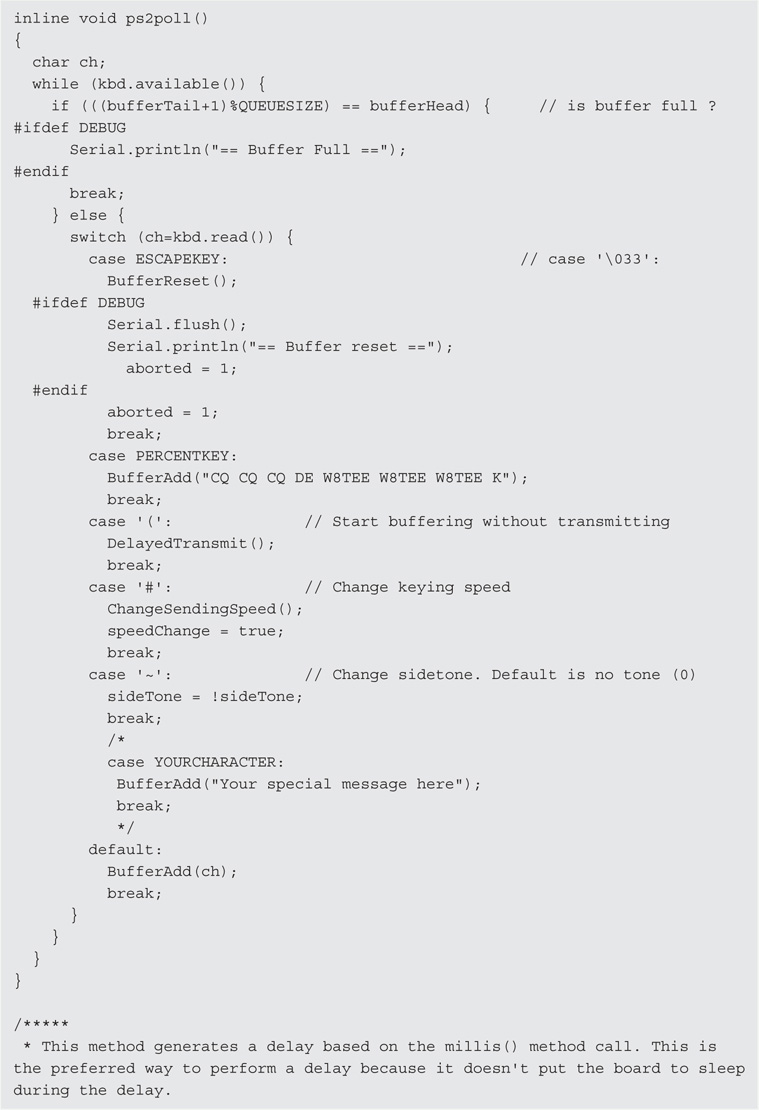
We left a number of DEBUG directives in the code. These lines enable you to view the code being produced on the Serial monitor. Just comment out the #define DEBUG 1 preprocessor directive when you are finished debugging/viewing the code.
Next is the statement:
int ditlen = 1200 / WORDSPERMINUTE;
This is one of the few times we leave a magic number in the source code; 1200 in this case. The details for this magic number can be found at http://en.wikipedia.org/wiki/Morse_code. Basically, it assumes a 50 dit duration period for a standard word and can be stated in units of time. (The word PARIS is often used as the standard word.) Once the time for a dit is calculated, all other spacings are based on it. Note that we have arbitrarily set the words per minute (wordsPerMinute) to 15 in the listing. You can change this to whatever reasonable speed you wish as the default speed at program startup.
Next are the standard setup() and loop() methods. We use pin 13 to blink the onboard LED in sync with the code being generated. If you tie a speaker to pin 10, make sure it is small and that you use a current limiting resistor in the line. Within loop(), the code constantly calls ps2poll() to look for a character from the keyboard, placing any character read into the buffer[] array. If there is a character in the buffer, the send() method is called to ultimately send the character to the transmitter.
Overloaded Methods
If you look at lines 92 and 110 in the listing (place the cursor on a source code line in the IDE and the line number is displayed in the lower left corner of the IDE), you can see:
void BufferAdd(char ch)
void BufferAdd(char *s)
Whoa! How can this be? Both methods have the same name, so why doesn’t the compiler issue a duplicate definition error? The reason is because C++ allows methods to share the same name as long as their parameter lists are different. In the first method, the parameter is a character, like ‘A’ or ‘B’. In the second method, the parameter is a pointer to a character. Because a valid pointer variable can only have one of two values, null or a valid memory address (and not a character), the compiler is smart enough to know which one of the two methods to use when the program needs to call one of these methods. (The method name and its parameter list are often referred to as the signature of the method. The process of using two methods with the same name, but different parameter lists, is called method overloading. You’d be surprised how often that little factoid comes up in cocktail conversation. Like Jack’s four-year-old grandson says … more “qwap” for your brain! Jack has no clue where he learned such terms.)
The compiler figures out which method to call by looking at the type of parameter(s) being passed to it and comparing signatures. Of course, the programmer can screw things up by using the wrong parameter type; the compiler is only smart enough to do what the programmer tells it to do. You can see the difference between the calls by looking near lines 189 and 192 in Listing 9-1. (Recall that the small number in the lower-left corner of the IDE is the current line number of the cursor in the source code window.) The first use is a long string of characters that is resolved to a pointer (an lvalue). The second method call simply passes in a single character.
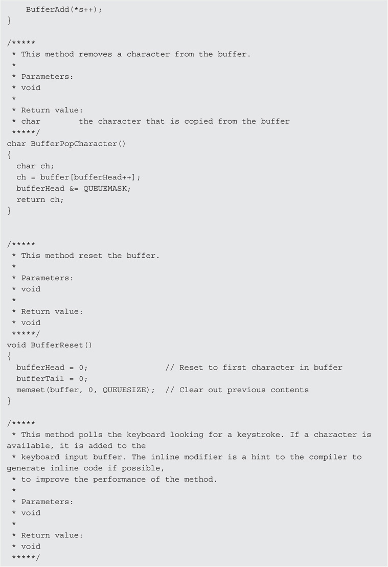
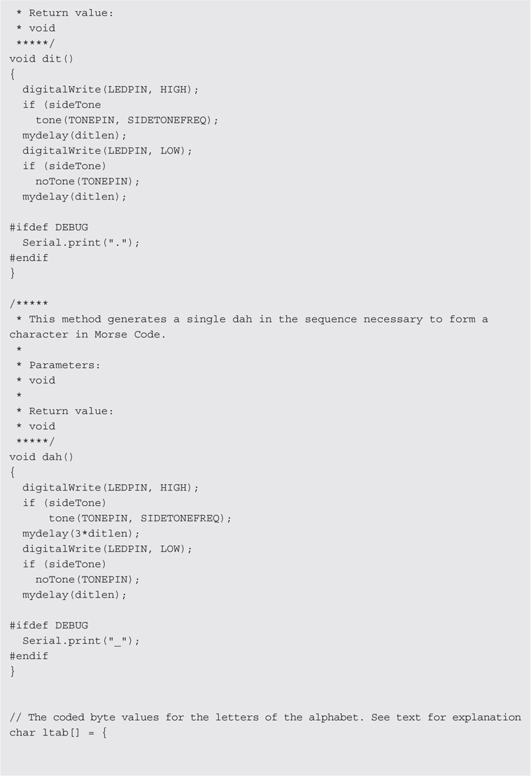
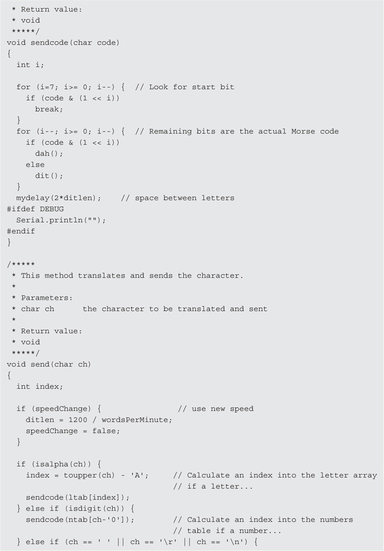
The sendcode() Method
Perhaps the hardest method to understand is the sendcode() method. We’ll use a single letter to help you understand what the method (and the program) is doing. First, suppose you type in the letter ‘a’ at the PS2 keyboard. The ps2poll() method reads that letter and stuffs it into the buffer[] array by calling BufferAdd(). Because the buffer is not empty now, BufferPopCharacter() is called. BufferPopCharacter() simply gets whatever character is being pointed to by bufferHead (and adjusts its value to prepare for the next character) and returns the character back to loop().
However, the character returned from the call to BufferPopCharacter() becomes the argument passed to the send() method. In essence, line 80 now looks like:
send(‘a’);
The first statement in send() is:
if (isalpha(ch)) {
if (isalpha(‘a’)) {
Because the character ‘a’ is an alpha character, the if expression is logic True. Therefore, the next statement executed is:
index = toupper(ch) – ‘A’;
which may be viewed as:
index = toupper(‘a’) – ‘A’;
Because the toupper() method (actually, it’s a macro, but we need not get into that) converts the lowercase ‘a’ to an uppercase ‘A’, the last statement becomes:
index = ‘A’ – ‘A’;
At first blush, it seems weird to subtract letters from one another. However, recall that the keyboard is actually sending ASCII (American Standard Characters for Information Interchange) values for every character that is pressed on the keyboard. The ASCII value for ‘A’ is 65; therefore, the last statement above becomes:
index = 65 – 65;
which resolves to 0, and that value is assigned into index. (You should ask yourself what would index be if the character was a ‘b’ or an ‘n’. If you understand those values, you’re right on track! An easy-to-read ASCII table can be found at http://www.asciitable.com/.) Because the ASCII values are in alphabetical order, it’s pretty easy to figure out what happens to index using different letters.
Now look at the next statement:
sendcode(ltab[index]);
Because we now know that index for ‘a’ becomes 0, the call is actually:
sendcode(ltab[0]);
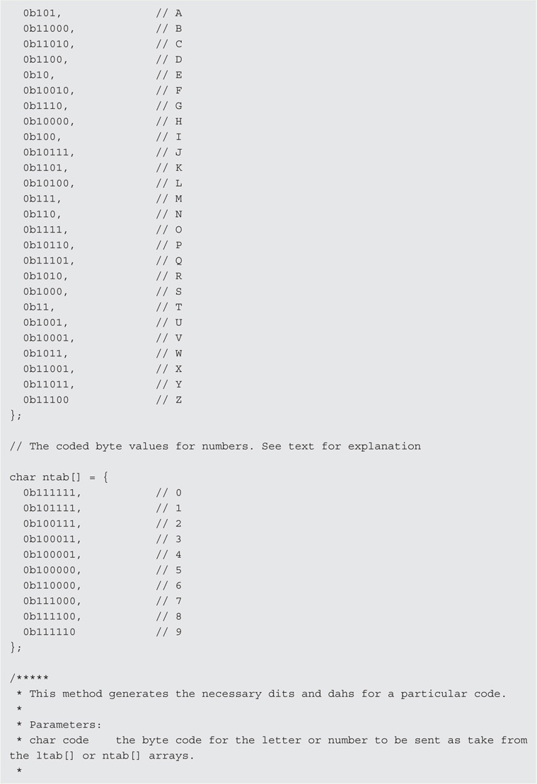
If you look at the first element in the ltab[] array (i.e., the letter table array), its value is 0b101. The leading “0b” tells the compiler that what follows is a byte value expressed in binary terms (the “0b” component in the statement stands for “binary”). You can see by the comment in the listing that this is the letter ‘A’. If you know Morse code, you know that the letter ‘A’ is di-dah. If you look at the second entry in the table, you see the letter ‘B’ is coded as 0b11000. The letter ‘B’ in Morse code is dah-di-di-dit. Hmmm. If we strip away the first binary bit (which is always a 1 in the ltab[] array), and treat a 1 as a dah and a 0 as a dit, it seems that the letter array is actually the Morse code equivalents for all of the letters of the alphabet. Shazam . . . an Ah-Ha moment!
Some Bit-Fiddling
You can see the following code snippet in the sendcode() method:
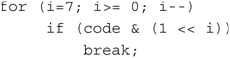
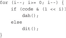
If you’re not familiar with bit shifting, the second statement above may look a little strange because of the bit shift left operator (<<). Recall that code at this point in the program equals 0b101. However, expressed as a complete binary byte value, code is actually 00000101. Note that the for loop starts with 7 and decreases the value of i on each pass through the loop. In other words, the loop starts looking at the bits in code starting with the last (7th or high) bit. Because the first five bits are all 0s, the if test spins past these five bits because the bitwise AND operator, &, and the bit shift left expression (1 << i) evaluates to logic False for each 0 bit read. This means the break statement to terminate the for loop is not executed until the first 1 is read from the code variable. Table 9-1 shows what is happening to the if expression on each pass through the for loop.
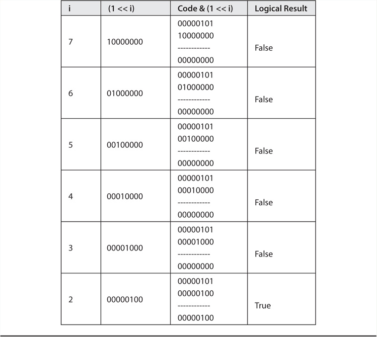
TABLE 9-1 Evaluation of the Statement: if (code & (1 << i))
Notice how the bit mask in column two in Table 9-1 changes with each pass through the for loop because of the bit shift left operator. Also note that, when i = 2 the if expression evaluates to logic True, which causes the break statement to be executed. This is because the bit mask is ANDed with code and produces a nonzero result.
The break statement causes execution of the first for loop to end and execution proceeds to the first statement that is not part of the controlling for loop. The next statement that is executed, however, is actually a second for loop as seen in the next code snippet:
The same if test is applied to the remaining part of the variable named code. Note that variable i is not initialized in the second for loop; variable i remains equal to the value of i from the previous for loop. The for loop decrements i before it is used, so i is now equal to 1 when the if test in the second for loop is executed. Table 9-2 shows what is happening on each pass through the second for loop.
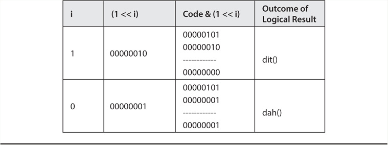
TABLE 9-2 Second for Loop Evaluation of the Statement: if (code & (1 << i))
Notice that when the if expression evaluates to logic False a dit is sent via the call to method dit(). Likewise, when the if expression evaluates to logic True, a dah is sent via a call to method dah().
You should now be able to figure out why the ltab[] array has elements whose binary values all begin with a 1. The algorithm uses the leading 1 to indicate that the bits that follow it decode into the appropriate dits and dahs for the characters in the array. While you could also implement this algorithm as a more simple rat’s nest of cascading if statements, this algorithm is much more efficient.
It’s worth the effort to spend enough time with this section to understand what the code is really doing. Bit shifting instructions execute extremely fast in the processor and are often a good solution to a variety of programming problems.
Isolating the Arduino from the Transmitter
With the software under your belt, we can finish up the circuit that ends up actually keying the transmitter. Because it’s just a good idea to isolate the Arduino circuitry from the transmitter, we decided to use an optoisolator IC to segregate the two circuits.
We chose to use the 4N26 chip simply because we had some lying around. You can purchase these for under $0.50 each either using some of the suppliers mentioned in Appendix A or online. The selection of this chip is not etched in stone and you can use others provided they can handle the I/O voltages and current.
The 4N26 is a 6-pin IC that is configured as shown in Figure 9-5. Note the current limiting resistor (470 Ω) on pin 1 of the 4N26, which is then tied to pin 13 of the Arduino. Pin 2 of the 4N26 is tied to ground and pins 3 and 6 are not connected. Pin 5 goes to the positive lead in your transmitter’s keying circuit and pin 4 is tied to its ground. Usually, this just means that pins 4 and 5 are terminated with a jack that plugs into your CW rig. This simple circuit can key most modern rigs that have a positive line going to ground when keyed.

FIGURE 9-5 Optoisolator circuit for 4N26.
Because we’re not big fans of soldering ICs directly into a circuit, we modified an 8-pin IC socket for use with the 4N26. In our case, we simply took a pair of needle-nosed pliers, grasped what is pin 4 on the 8-pin IC socket, and pushed the pin up and out through the top of the socket. We then repeated the process for pin 5 on the socket. The results can be seen in Figure 9-6.
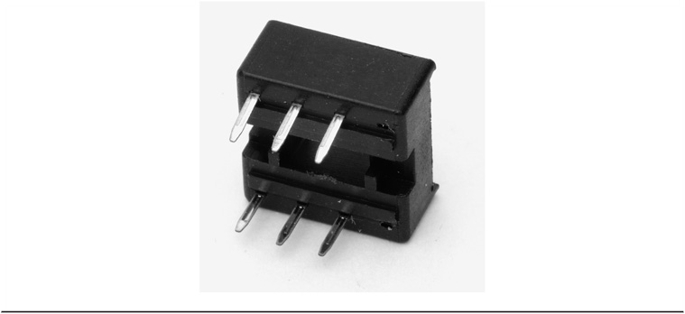
FIGURE 9-6 An 8-pin IC socket with pins 4 and 5 removed.
After butchering the socket as we did, we moved it to our small perf board and wired it according to Figure 9-5. The final results can be seen in Figure 9-7. The connection to pin 13 of the Arduino is partially blocked in the photo, but you can see the current limiting resistor at the edge of the perf board. The two leads labeled Key Out are to the transmitter’s keyed circuit. The PS2 leads were discussed earlier in this chapter. The two leads heading north go to a super-small 8 Ω speaker that has a 1K Ω resistor in the lead that ties into pin 12 (see Listing 9-1 and look for TONEPIN near the top of the listing). The other speaker lead is attached to a GND pin on the Arduino board. (You could also use a small buzzer instead of the speaker.)

FIGURE 9-7 The finished circuit.
The schematic for the complete circuit is shown in Figure 9-8. (The circuit does not show the power source for the Arduino, although the USB supplies the power while testing the circuit and the software. Most people will power the final circuit with an inexpensive 6 V wall wart power adapter using the barrel power connector on the Arduino.)
FIGURE 9-8 The PS2 keyboard encoder circuit.
Testing
Testing both the software and hardware should be done before you commit the circuit to its final state (e.g., moving it to a “real” shield). If you look at Listing 9-1 closely, the first statement after the #include is:
#define DEBUG 1 // For debugging statements. Comment out when not debugging
(which you have seen before). The DEBUG symbolic constant is used to toggle debugging code into and out of a program. In this program, the DEBUG symbolic constant changes the output so it can be viewed on the Serial output tied to your PC. When you first see the string “PS2 keyboard ready:” appear on the monitor, you can start typing on the PS2 keyboard. (Did any of you type on your PC keyboard instead of the PS2 keyboard and wonder why nothing happened? We did … briefly.) If all goes well, you should see the letters you typed appear on the Serial monitor. For example, we typed in “This is a test” and the Serial monitor showed the results as shown in Figure 9-9.
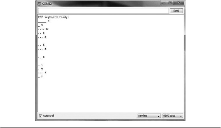
FIGURE 9-9 Program output in DEBUG mode.
Of course, you should to comment out the #define DEBUG 1 statement line when you actually want to use the program so time isn’t spent sending data to the Serial output.
You can compare the cobbled test version of the PS2 keyer in Figure 9-7 with the shield version shown in Figure 9-10. In Figure 9-10 you can see a small buzzer onboard to act as a side tone using pin 10 as shown in the code listing.

FIGURE 9-10 PS2 keyer shield.
Other Features
The following sections detail several features that may not be obvious when the program is executing. (Of course, you already know about these features because you poured over Listing 9-1 with a fine-toothed comb, right?)
Change Code Speed
The default code speed is 15 words per minute (wpm). Obviously, this doesn’t mean a whole lot because words have differing lengths. However, way back when, the FCC’s rule was that a word consisted of five letters, so 15 wpm is about 75 characters a minute, or a little more than a character a second. For experienced CW enthusiasts, 15 wpm is a glacial pace. For us mere mortals, it’s a pretty comfortable speed. However, no matter how fast you can send and receive, you may wish to make a contact with someone who is sending faster or slower than you are currently set up to transmit.
Rather than change the speed setting in the program and make you recompile and upload it, the code supports on-the-fly speed modifications. Around line 200 in Listing 9-1 you can see a case statement based on the ‘#’ sign. When the code reads a ‘#’ sign from the PS2 keyboard, method ChangeSendingSpeed() is called. If the next character read from the keyboard is a greater than sign (‘>’), the wpm is bumped up by one. So if you want to increase the speed from 15 to 20 wpm, you would type in the following characters:

As you can see, the ‘#’ character triggers the call, but the same character is also used to terminate the speed adjustment. The program then resumes its normal operation, but at the newly assigned speed. If, after pressing the first # key you had pressed the less than key (‘<’) five times, you would have decreased the keying speed to 10 wpm. These key combinations allow you to change the speed without recompiling the code.
Sidetone
The default mode is for the program not to generate a sidetone. Usually, most rigs have their own sidetone and have the program code default to generating a second sidetone would just confuse things. However, during testing or perhaps trying to improve your code speed, you may want to have a sidetone.
At about the same place in the code listing, you’ll see that the tilde character (‘~’, located to the left of the ‘1’ key on the keyboard) is used in another case statement. When the tilde is read, it causes the variable named sideTone to be toggled. Since sideTone is a boolean data type, it starts with the value False so there is no sidetone. If you press the tilde key, sideTone is toggled, changing its value to True. If you look at the dit() and dah() methods, you’ll see how the sideTone works. Pressing the tilde key a second time again toggles the sideTone variable, thus setting it back to False and turning the sidetone off.
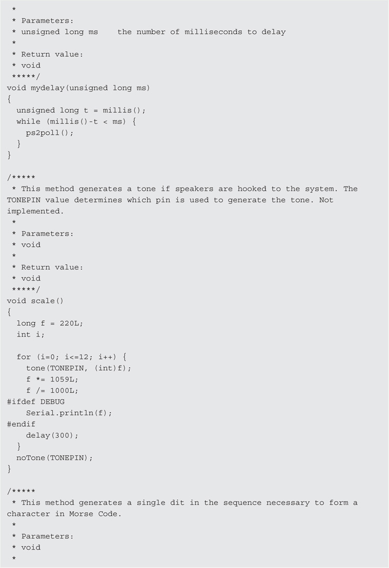
The sideTone feature assumes that you have a small speaker or buzzer attached to pin 12 on the Arduino and the other side tied to ground. We used a 1000 Ω current limiting resistor on the lead going to pin 12, which produces a very weak background sidetone. Almost any value between 400 and 1000 Ω will work. Forgetting a current limiting resistor could fry your Arduino, so make sure you add it to your circuit.
Long Messages
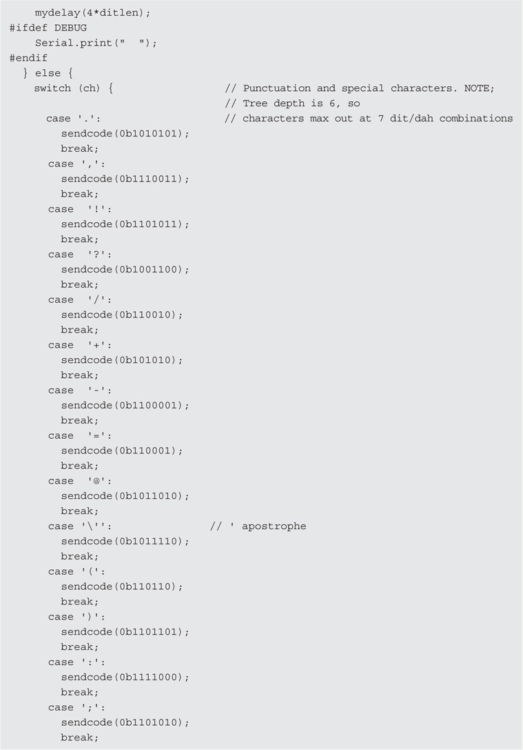
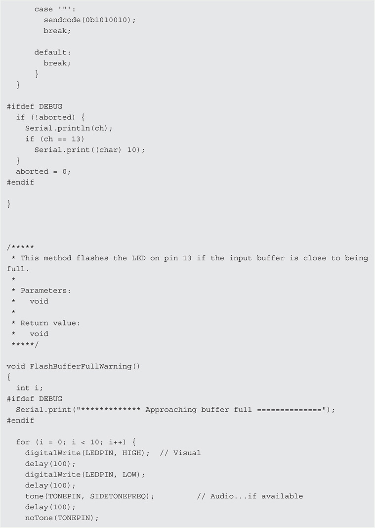
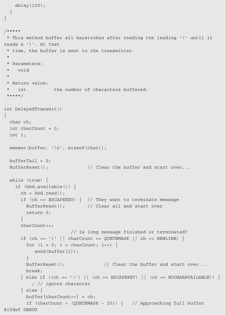
Sometimes when you’re rag chewing it’s nice to be able to make notes so that when your turn comes, you remember what it was you wanted to say. (We’re old, remember?) Again, looking near line 200 in Listing 9-1 you’ll see a case statement that executes when it sees an opening parenthesis (‘(’) character. After reading a ‘(’, the DelayedTransmit() method is called. All this does is buffer whatever keystrokes follow the ‘(’ until a closing parenthesis (‘)’) character is read. At that time, the contents of the buffer are sent in normal fashion.
In the code, if you start to fill up the buffer to the point where it might overflow, the Arduino LED starts to flash at a rate of 10 times per second. As the code currently stands, the flashing starts when the buffer has QUEUEMASK − 20, which resolves to 107, characters of empty buffer space remaining. Of course you can change this, but it’s probably a good idea to have some indicator for pending buffer overflow.
So, how would you use this feature? Probably, you would type in the opening parenthesis followed by the normal QSO resume pattern (e.g., W8XYZ DE W8TEE R) and then start typing the message that you wanted to send. If you’re using a break-in type of QSO where you go back and forth without sending call signs, the long message feature doesn’t makes a lot of sense. If it’s a feature you don’t think you’ll use, don’t send an opening parenthesis!
Conclusion
The program could benefit from some additions. For example, another addition would be to add the LCD display from Chapter 3 to the circuitry so you could see what you are typing as you type it. There are a lot of keys on the keyboard that remain uncoded. You can use these for additional commands you may think useful. If you do make improvements to either the hardware or software, don’t forget to share it with the rest of us by posting it on the web site, http://arduinoforhamradio.com.