
CHAPTER 11
Universal Relay Shield
One of Dennis’s many interests in ham radio involves “boatanchor” radios … you know, the ones that cause the house lights to dim when you turn them on and then glow in the dark if you turn the lights out. Every now and then he runs across an application for an Arduino that would be ideal for controlling one of these old sets, but the digital IO pins just can’t handle the higher voltages used in these old radios. The solution is to use a relay.
There are many relays that can be controlled by a 5 VDC signal and with sufficiently low current as to not stress the IO pins on the Arduino. These relays can switch several hundred volts and a respectable amount of current and come in a very compact size. Figure 11-1 shows some examples of miniature relays. The relays shown all have 5 VDC coils and can switch from 250 mA (the reed relay in the lower right) up to 30 A (the brute in the upper left). These relays are designed to be mounted on a circuit board, such as our Arduino prototyping shields.

FIGURE 11-1 Typical PCB mounted miniature relays.
If you need to control even higher current or voltage than the miniature relays we have chosen, you can always use an external relay with contacts rated for your application. The relays and sockets shown in Figure 11-2 are some examples that can handle high current and high voltage, such as would be used to switch mains power.
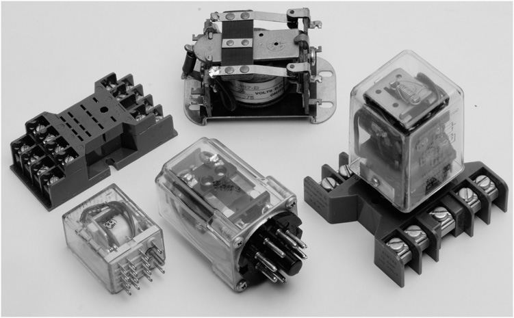
FIGURE 11-2 An array of high current, high voltage relays.
This chapter presents a project that constructs a relay shield. Figure 11-3 shows a version of the relay shield. The shield contains four double pole double throw (DPDT) relays that can switch up to 250 VAC at 2 A per contact! The relays we chose only draw 25 mA at 5 VDC, which is probably within the acceptable range for one or two relays being driven (the Arduino can source or sink up to 33 mA on an IO pin), but driving four relays simultaneously can potentially damage the μC. We chose to use the digital IO pins with a current driver to operate the relays. By using the current driver, we do not exceed the current limits of the Arduino.
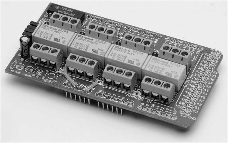
FIGURE 11-3 A Universal relay shield.
Each relay includes an LED to indicate the operational status of the relay. Another nice feature: a removable jumper that allows you to test your programming without actually engaging the relays, but using the LEDs as an indicator of the relay operation. This can be very helpful during debugging when you might not want to actually operate the piece of equipment the relays are going to control. In addition, the relay contacts are brought out to heavy-duty screw terminals, making connection to the external controlled device much easier.
This project is the basis of three projects later in the book; an antenna rotator controller and a sequencer for controlling low noise preamplifiers and power amplifiers. A third project is based on the relay shield circuit, but is assembled using a different style prototyping board to build a sequencer.
Construction
The relay shield is assembled on a Mega prototyping shield. This shield provides sufficient “real estate” for all four relays and the associated circuitry. The good news is that the Mega shield does fit an Arduino Uno, Demilenova, and so forth, without any problem. We just don’t use all of the headers; only those headers that are common to an R3 shield. As always, there is no rule that says you must build the circuit in this manner. In fact, you might not need four relays or even DPDT relays for your application; remember that the circuit is quite scalable both up and down in size. One possible option would be to use an R3 shield and a header to a ribbon cable to connect to a larger prototyping board with more than four relays. The possibilities are limited only by your needs and your creativity.
Circuit Description
The schematic for the relay shield is shown in Figure 11-4. For the sake of clarity, only one relay circuit is shown. The remaining three are wired identically. Each relay is driven by one section of a DS75492 hex driver chip. The DS75492 is rated at 250 mA current per output pin, not to exceed 600 mA total for the device. The DS75492 is an “open-collector” output device, meaning that the relay is connected to the positive supply while the DS75492 provides switching to ground. A “HIGH” output from the Arduino actuates the relay. The driver output is connected directly to the LED indicator for that section, and the relay is connected through a two-pin jumper. By using the jumper (JP1 in Figure 11-4), the relay can be disabled for testing by removing the jumper while the LED provides an indication that the output is being driven. This prevents “accidents” from happening when driving the external circuits connected to the relay.

FIGURE 11-4 Universal relay shield schematic diagram.
The parts list for the relay shield is shown in Table 11-1. Most of the components are sourced from eBay; however, the DS75492 is easily purchased from Jameco (http://www.jameco.com).
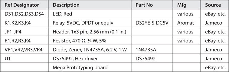
TABLE 11-1 Universal Relay Shield Parts List
Construction of the Relay Shield
Our example relay shield, as shown in Figure 11-3, is assembled on a Mega prototyping shield. This shield functions on multiple Arduino platforms as they share a common layout for the power, six analog in and 14 digital IO pins. We didn’t use the other IO pins and only installed the four headers needed for those pins. Figure 11-5 shows the layout we have used.
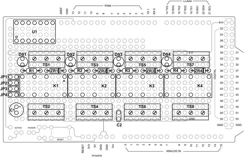
FIGURE 11-5 One possible layout of the relay shield.
The reverse side of the shield is shown in Figure 11-6. Wiring is done as described in Chapter 3, using bare wire from components leads, and Teflon tubing for insulation. Because of limited “real estate” on the prototyping shield and clearance issues with the screw terminals near the current driver IC, we chose to connect directly to the leads of the IC rather than using a socket. A socket would have obstructed the wiring to the adjacent screw terminals. If you decide on this method of construction, use extra care when soldering wires to the current driver. The wiring side of the completed relay shield is shown in Figure 11-7.
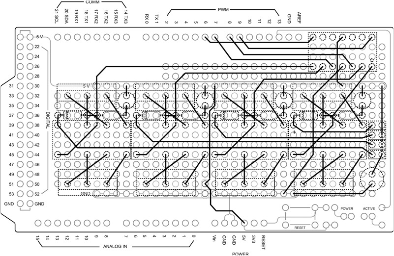
FIGURE 11-6 The “Backside” of the relay shield showing the wiring.
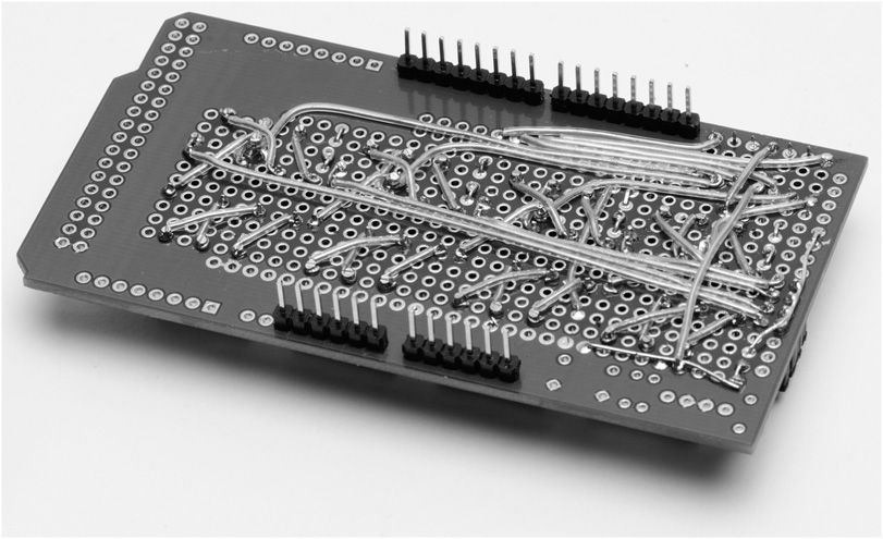
FIGURE 11-7 The wiring side of the completed relay shield.
Testing the Relay Shield
We have provided a sketch that you can use to test that the relays are functioning as expected. The program energizes each relay in sequence. The corresponding LED should also light up when that relay is energized.
After having checked all of your wiring (you have checked your wiring, yes?), you can attach the relay shield to an Arduino and apply power. Assuming there is no program in the Arduino that would set any of the output pins we are using to HIGH, none of the LEDs should be lit. If there are any LEDs lit, then either a program in the Arduino is setting that particular output HIGH or there is a wiring error. If none of the LEDs are lit you can proceed with the next test by compiling and loading the sketch shown in Listing 11-1. This sketch turns each relay on and then off, in sequence, on about a one-half second interval. You can observe that the LEDs are cycling in sequence. Next, insert the jumpers to enable the relays and observe that they are cycling as well.
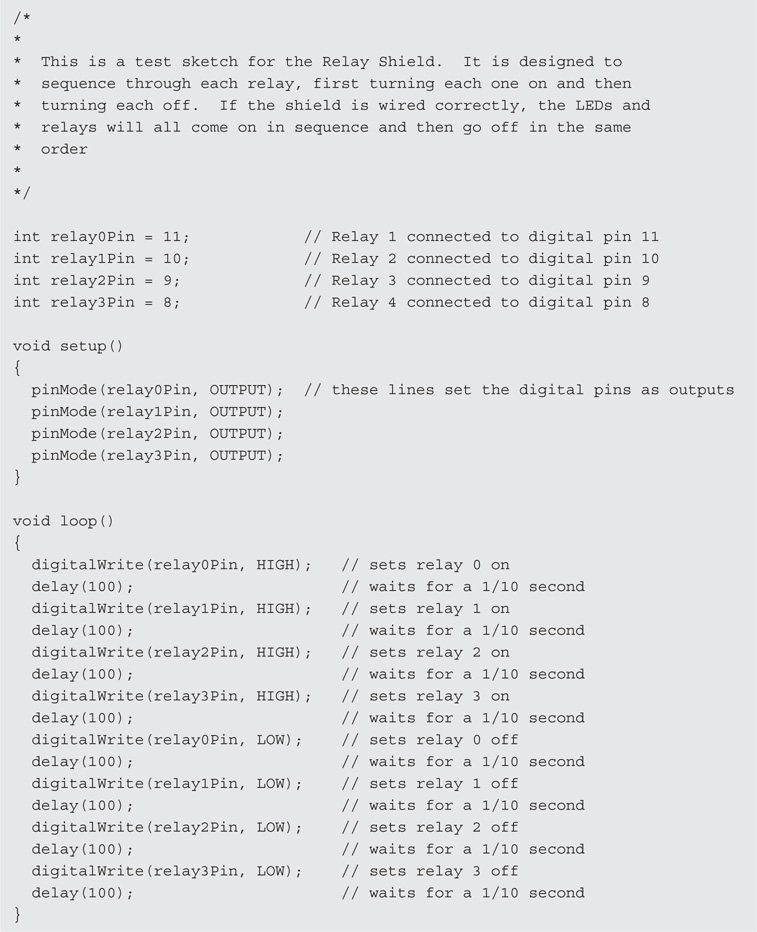
LISTING 11-1 A test sketch for the relay shield.
Test Sketch “Walk-Through”
The code used to test the relay shield is pretty straightforward. We define the Arduino digital IO pins that drive the relays and set their mode to OUTPUT. Next, we set each pin HIGH in sequence on ![]() second intervals and then set each pin LOW in sequence on
second intervals and then set each pin LOW in sequence on ![]() second intervals. It should take
second intervals. It should take ![]() second to complete one cycle for all four relays.
second to complete one cycle for all four relays.
Conclusion
This shield along with the test sketch does not do a great deal on its own other than verify the functionality of the relay shield. The relay shield, however, becomes an integral part of three upcoming projects; a rotator controller and two versions of a sequencer. In any case, you may find other applications for the relay shield. In Dennis’s case, he is using one to control a repurposed AM broadcast transmitter. The transmitter uses four momentary contact pushbuttons and two latching relays to control the AC power and high voltage, respectively. Dennis wanted to be able to control the transmitter remotely using a pushbutton to turn the power on and off and a lever switch to turn on the high voltage for transmit. The program Dennis uses applies a 100 ms pulse to the appropriate relay to simulate the pushbuttons on the transmitter. Latching relays do not like to have continuous power applied to the coil. As for the lever switch, he just determines if the switch has been moved and to what position it moved and triggers the appropriate relay with a 100 ms pulse.
Maybe you have similar applications that can benefit from the relay shield. There’s nothing etched in stone that requires this shield to be used only with your amateur radio equipment. A little thought “outside the box” will likely reveal other uses. While it takes a little more hardware and software than we want to get into here, you can activate an Arduino via a cell phone and Internet connection. Using that type of setup, the relay shield could be used for everything from remote warm-up of the rig to activating a burglar alarm system. Think about it …